1
D6600/D6100 | Operation and Installation Guide | 3.0
3.1.3
Card Functions and Locations
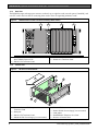
Rear View
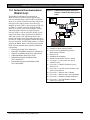
The D6600 has input and output pin connector sockets for up to eight line cards, network option (if installed), and
one CPU card. It also has slots for connecting these cards to their corresponding terminator cards.
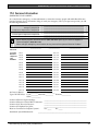
Figure 2:
D6600 Communications Receiver/Gateway (Rear VSiew)
1
2
3
4
Bosch Security Systems
Fairport, NY
USA
1
2
3
4
B
A
T
T
E
R
Y
Input:
100 - 120/
220 - 240V~
50 - 60 Hz
2.5 Amps
1 – Blank plate and location of installed D6672
Serial COM1 Expansion Kit
2 – D6615 CPU Terminator Card
3.1.4
3 – Card slot covers
4 – D6645 Line Terminator Card
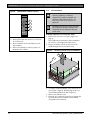
Internal View
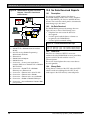
Figure 3:
Receiver Card Placement
1
9
2
3
5
4
8
7
1 – D6645 or D6645INTL Telephone Line
Terminator Card
2 – Back plate
3 – D6615 CPU Terminator Card
4 – D6630 AC/DC Power Supply (not serviceable)
8
6
5–
6–
7–
8–
9–
D6610 CPU Card
D6631 DC/DC Power Supply (not serviceable)
Card guides
D6640/D6641 Telephone Line Card
Direction of receiver front
Bosch Security Systems | 4/05 | 4998122704F