1
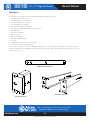
Owner’s Manual
MMK15-RM
MMK17-RM
15" / 17" Single Rail Console
MMK15-RM / MMK17-RM
15" / 17" LCD
Single Rail Console with Modular KVM Switch
1601 Jack McKay Blvd. • Ennis, Texas 75119 U.S.A.
Telephone: 800.876.3333 • Fax: 800.765.3435
– 1 –
Specifications are subject to change without notice.
AtlasSound.com
MMK15-RM
MMK17-RM
Owner’s Manual
15" / 17" Single Rail Console
Packing List
The complete 15" / 17" single rail console with modular KVM switch package consists of:
• One 1RU 19" Rack Mount Console
• Two Rails with Front and Rear Bracket
• Two Extended Brackets. (See Below)
• Two Short Brackets. (See Below)
• Two Bracket Attachments. (See Below)
• One 5.9' (1.8 m) KVM cable. (HDDB-15 / VGA + PS/2 x 2)
• One USB Cable
• One DC Power Adapter
• One Power Cord
• One User Manual CD
• One Quick Installation Guide
• Two Keys
• Six Flat Screws (for rail mount to console body)
• Six Screws (for replace extended bracket)
Check to make sure that the unit was not damaged in shipping. If you encounter a problem, contact Atlas Sound. Please read this
manual thoroughly, follow the installation and operation procedures carefully to prevent any damage to the product, and / or any of the
devices that connect to it.
TWO Bracket Attachments
Two Extended Brackets
Two Short Brackets
1601 Jack McKay Blvd. • Ennis, Texas 75119 U.S.A.
Telephone: 800.876.3333 • Fax: 800.765.3435
AtlasSound.com
– 2 –
Specifications are subject to change without notice.
MMK15-RM
MMK17-RM
Owner’s Manual
15" / 17" Single Rail Console
Safety Instructions
The lightning flash with arrowhead symbol within an
equilateral triangle, is intended to alert the user to the
presence of uninsulated “dangerous voltage “ within the product’s enclosure that may be of sufficient magnitude
to constitute a risk of electric shock to persons.
CAUTION
er
35
35W
gineered
und
INA
RISK OF ELECTRIC SHOCK
DO NOT OPEN
ATTENTION
´
RISQUE DE DECHARGE ELECTRIQUE
-NE PAS OUVRIR.
The exclamation point within an equilateral triangle is
intended to alert the user to the presence of important
operating and maintenance (servicing) instructions in the
literature accompanying the product.
WARNING
TO REDUCE THE RISK OF FIRE OR ELECTRIC SHOCK
DO NOT EXPOSE THIS APPLIANCE TO RAIN OR MOISTURE.
1. Read these instructions.
2. Keep these instructions.
3. Heed all warnings.
4. Follow all instructions.
5. Do not use this apparatus near water.
6. Clean only with dry cloth.
7. Do not block any ventilation openings. Install in accordance with the manufacturer’s instructions.
8. D
o not install near any heat sources such as radiators, heat registers, stoves, or other apparatus (including amplifiers) that produce
heat.
9. D
o not defeat the safety purpose of the polarized or grounding-type plug. A polarized plug has two blades with one wider than the
other. A grounding type plug has two blades and a third grounding prong. The wide blade or the third prong are provided for your
safety. If the provided plug does not fit into your outlet, consult an electrician for replacement of the obsolete outlet.
10.Protect the power cord from being walked on or pinched particularly at plugs, convenience receptacles, and the point where they
exit from the apparatus.
11.Only use attachments/accessories specified by the manufacturer.
12.Use only with the cart, stand, tripod, bracket, or table specified by the manufacturer, or sold with the apparatus. When a cart is
used use caution when moving the cart/apparatus combination to avoid injury from tip-over. 13.Unplug this apparatus during lightning storms or when unused for long periods of time.
14.Refer all servicing to qualified service personnel. Servicing is required when the apparatus has been damaged in any way, such
as power-supply cord or plug is damaged, liquid has been spilled or objects have fallen into the apparatus, the apparatus has been
exposed to rain or moisture, does not operate normally, or has been dropped.
15.WARNING: To reduce the risk of fire or electric shock, this apparatus should not be exposed to rain or moisture and objects filled
with liquids, such as vases, should not be placed on this apparatus.
16.To completely disconnect this equipment from the mains, disconnect the power supply cord plug from the receptacle.
17.The mains plug of the power supply cord shall remain readily operable.
1601 Jack McKay Blvd. • Ennis, Texas 75119 U.S.A.
Telephone: 800.876.3333 • Fax: 800.765.3435
– 3 –
Specifications are subject to change without notice.
AtlasSound.com
MMK15-RM
MMK17-RM
15" / 17" Single Rail Console
Owner’s Manual
CAUTION – When Installing the Product
• Plugging in or unplugging the power cord with wet hands may result in electric shock.
• N
ever move the unit with the power cord plugged into the wall, as damage to the power cord may
result.
• When unplugging the cord from the wall, grasp the plug, NOT the cord.
• N
ever install this product in humid or dusty locations, nor in direct sunlight, near sources of heat, or in
areas where sooty smoke or steam are present. Fire and electric shock may result.
• K
eep all sides of the unit at least 31⁄2" away from objects that may obstruct air flow to prevent the unit's
internal temperature rise.
WARNING – When the Device is in Use
• T
o prevent electric shock, do not remove the product cover as there are high voltage components inside. Refer all servicing to Atlas
Sound.
• S
hould any of the following irregularities occur during use, immediately switch off the power, disconnect the power cord from
the AC outlet and contact Atlas Sound. Do not to attempt to continue operation with the product as this may cause fire or electric
shock:
• Smoke or strange smell coming from the unit.
• If the product falls or the case is damaged.
• If water or any metallic objects falls into the product.
• If the power supply cord is damaged in any way.
• If the unit is malfunctioning.
• D
o not insert or drop metallic objects or flammable materials into the ventilation holes of the product's cover, as this may result in
electric shock or fire.
• D
o not place any containers with liquid or metallic objects on the top of the product. If any liquid spills into the unit, fire or electric
shock may result.
• Never operate this product or touch the power supply cord during an electrical storm, electric shock may result.
• Never exceed the wattage on the product when connecting equipment. Fire and/or property damage may result.
• Operate the product only with the voltage specified on the unit. Fire and/or electric shock may result if a higher voltage is used.
• D
o not modify, kink, or cut the power cord. Do not place the power cord in close proximity to heaters and do not place heavy
objects on the power cord, including the product itself, doing so may result in fire or electrical shock.
• E
nsure that the safety ground terminal is connected to a proper ground. Never connect the ground to a gas pipe as a catastrophic
disaster may result.
• Be sure the installation of the product is stable, avoid slanted surfaces as the product may fall and cause injury or property damage.
CAUTION – When the Device is in Use
• N
ever place heavy objects on the product, causing it to fall and/or break can result in personal injury and property damage. In addition, the product itself may fall and cause injury and property damage.
• C
ontact Atlas Sound for instructions on cleaning the inside of the unit. Large accumulations of dust inside the unit may result in
heat buildup and fire.
• E
nsure that the power supply plug is securely plugged into the wall outlet. Never allow dust to accumulate on the power plug or
inside the wall outlet.
• When cleaning the unit or the unit is not to be operated for an extended time period, unplug the power cord from the wall.
1601 Jack McKay Blvd. • Ennis, Texas 75119 U.S.A.
Telephone: 800.876.3333 • Fax: 800.765.3435
AtlasSound.com
– 4 –
Specifications are subject to change without notice.
Owner’s Manual
MMK15-RM
MMK17-RM
15" / 17" Single Rail Console
Table of Contents
Packing List.....................................................................2
3. Installation........................................................................14
3.1 3.1.1 Notes................................................................14
3.1.2 Hardware Kits Contents...................................15
3.1.3 Step A (Install Console):...................................16
3.1.4 Step B (Replace short bracket):........................19
1. General Information.......................................................6
3.1.5 Step C (Replace extended bracket):.................20
1.1 Feature...............................................................6
3.1.6 Unload Step......................................................21
1.2 Advantage...........................................................6
3.3 1.3 Product Specification..........................................7
3.3.1 Hardware Kits Contents...................................23
1.3.1 15" / 17" Single Rail Console
with Modular KVM Switch Specification...........8
3.3.2 Install Modular KVM Switch Step....................23
3.4
3.4.1 Configuring the Display Settings......................24
3.4.2 Connecting the Console...................................25
3.5 Turning on the Console....................................25
3.6 Testing the Console..........................................25
Safety Instructions.........................................................3
Table of Contents............................................................5
2. Panel Controls and OSD Function..................................9
2.1
Auto Tune.........................................................10
2.2 Input Source.....................................................10
2.3 Brightness........................................................10
2.4 Contrast............................................................11
2.5 Color.................................................................11
2.6 Position.............................................................12
2.7 Language..........................................................12
2.8 Recall................................................................13
2.9 Exit....................................................................13
2.10
Power Indicator................................................13
Install 15" Single Rail Console into Cabinet......14
Install Modular KVM Switch Step....................23
Installing the Video Card and Video Driver.......24
4. Notes . ............................................................................26
Warranty . ............................................................................28
1601 Jack McKay Blvd. • Ennis, Texas 75119 U.S.A.
Telephone: 800.876.3333 • Fax: 800.765.3435
– 5 –
Specifications are subject to change without notice.
AtlasSound.com
MMK15-RM
MMK17-RM
1.
15" / 17" Single Rail Console
Owner’s Manual
General Information
Single rail consoles with modular KVM switch offer an industrial level input solution to optimize your space utilization by controlling your
systems in just 1RU.
1.1
Feature
• Easy to Install, Single Rail Design
• 15" / 17" LCD Panel Options
• Support Sun™ Native Resolution
• Support 17 Various Keyboard Languages (Increasing)
• Bright Active TFT Display
• OSD Function for LCD Display and KVM Switch
• Durable Keyboard (Touchpad)
• Panel Protected by Tempered Glass
• Integration with KVM Switches
1.2
Advantage
Easy to Install:
With the unique separate rail design. One man can install the console easily. In case you need to maintain the console, you can easily
uninstall without effecting the server above or below.
Modular KVM switches:
The user can use console as single port console or through some simple action and few screws to be 8 Port KVM console.
We support 17 keyboard languages to fit the demands of several countries.
1601 Jack McKay Blvd. • Ennis, Texas 75119 U.S.A.
Telephone: 800.876.3333 • Fax: 800.765.3435
AtlasSound.com
– 6 –
Specifications are subject to change without notice.
MMK15-RM
MMK17-RM
Owner’s Manual
1.3
15" / 17" Single Rail Console
Product Specification
1.3.1 15" / 17" Single Rail Console with Modular KVM Switch Specification
Model name
Model Name
MMK15-RM
MMK17-RM
Number Of Ports
1
Dimension
18.5" x 17.6" x 1.7" (470.1mm x 447.5mm x 44mm)
Package Dimension
23.9" x 21.7" x 9.0" (606mm x 551.5mm x 230mm)
Net Weight
26.46 lbs / 12 Kg
28.7 lbs (13.0Kg)
Gross Weight
43.0 lbs / 19.5 Kg
45.2 lbs (20.5Kg)
Display Size
15" (381 mm)
17" (431.8mm)
Panel Type
Active Matrix TFT LCD
Resolution Capabilities
Maximum Resolution up to 1024 x 768 (XGA)
Maximum Resolution up to 1280 x 1024 (SXGA)
Pixel Pitch
Supports 0.297mm x 0.297mm
Supports 0.264mm x 0.264mm
Viewing Angle (Cr>10)
Right-Left view 130° (Typ)
Right-Left View 60° (Typ)
Up-Down View 100° (Typ)
Up-Down View 45° (Typ)
Contrast Ratio
400:1
450:1
Brightness
White 250 cd/m2
Back Light
Dual Lamps
Supported Colors
16.7 M Colors (8-bit with FRC)
Response Time
Rising Time 5ms, Decay Time 11ms
Operating System
DOS, Microsoft Windows (3.1, 9x, 2000, NT4, ME, XP, 2003 Server),
Linux, Novell 3.12-6, HP UX, Sun
Multi Platform
Support PS/2 and USB
System Cables
VGA + PS/2 (x2) or VGA + USB (x1)
Keyboard Mouse
106 key PS/2 keyboard with touch pad
Sync
45kHz ~ 80kHz
Power Source
100VAC ~ 240VAC Input
Power Consumption
16 Watts, 10.41 Watts for Panel
Temperature
Operate: 32° ~ 122° (0°c ~ 50°c)
Four Lamps
Rising Time 2ms, Decay Time 14ms
™
F
25 Watts, 19.05 Watts for Panel
F
Storage: -4° ~ 140° (-20°c ~ 60°c)
F
F
Humidity
10% ~ 90% RH
Chassis Construction
Heavy Duty Steel Materials
Keyboard Language
USA, UK, German, French, Spanish, Italian, Portuguese, Dutch, Swiss, Belgium, Swedish,
Norwegian, Danish, Japanese, Taiwanese, Russian, & Hebrew
Certification
CE / FCC, UL / CUL / C-Tick, GOST
Table 1-1. 15" / 17" Single Rail Console with Modular KVM Switch Specification
1601 Jack McKay Blvd. • Ennis, Texas 75119 U.S.A.
Telephone: 800.876.3333 • Fax: 800.765.3435
– 7 –
Specifications are subject to change without notice.
AtlasSound.com
14.89" (378.2 mm)
AtlasSound.com
)
)
0.05"
(1.2 mm)
MMK17-RM
24.17" (614 mm)
– 8 –
Specifications are subject to change without notice.
18.98" (482 mm)
18.31" (465 mm)
Figure 1-1. 15" / 17" Single Rail Console with Modular KVM Switch Dimensions
5.39"
(137 mm)
1601 Jack McKay Blvd. • Ennis, Texas 75119 U.S.A.
Telephone: 800.876.3333 • Fax: 800.765.3435
14.89" (378.2 mm)
MMK17-RM
1.25" (31.8 mm)
1.73" (44 mm)
1.25" (31.8 mm)
14.89" (378.2 mm)
MMK17-RM
1.38"
(35 mm)
1.38"
(35 mm)
MMK15-RM
1.38"
(35 mm)
1.38"
(35 mm)
1.73" (44 mm)
1.25" (31.8 mm)
1.73" (44 mm)
14.89" (378.2 mm)
14.89" (378.2 mm)
1.25" (31.8 mm)
18.98" (482 mm)
18.31" (465 mm)
1.25" (31.8 mm)
24.17" (614 mm)
18.46" (468.9 mm)
24.17" (614 mm)
24.17" ~ 311.85."46" (468.9 mm)
(614 ~ 800 mm)
18.46" (468.9 mm)
1.73" (44 mm)
0.05"
(1.2 mm)
24.17" ~ 31.5"
(614 ~ 800 mm)
24.17" (614 mm)
24.17" ~ 31.5"
(614 ~ 800 mm)
1.38"
(35 mm)
15" / 17" Single Rail Console
1.73" (44 mm)
1.38"
(35 mm)
0.05"
(1.2 mm)
0.05"
(1.2 mm)
1.38"
(35 mm)
5.39"
(137 mm)
14.89" (378.2 mm)
1.25" (31.8 mm)
18.46" (468.9 mm)
1.73" (44 mm)
24.17" (614 mm)
18.46" (468.9 mm)
MMK15-RM
14.89" (378.2 mm)
24.17" ~ 311.85."46" (468.9 mm)
(614 ~ 800 mm)
18.98" (482 mm)
18.31" (465 mm)
0.05"
(1.2 mm)
1.38"
(35 mm)
0.05"
(1.2 mm)
24.(44
17" mm)
~ 31.5"
1.73"
(614 ~ 800 mm)
14.89" (378.2 mm)
1.25" (31.8 mm)
24.17" (614 mm)
24.17" ~ 31.5"
(614 ~ 800 mm)
MMK15-RM
MMK17-RM
Owner’s Manual
5.39"
(137 mm)
5.39"
(137 mm)
5.39"
(137 mm)
MMK15-RM
MMK15-RM
18.98" (482 mm)
18.31" (465 mm)
18.98" (482 mm)
18.31" (465 mm)
5.39"
(137 mm)
5.39"
(137 mm)
5.39"
(137 mm)
18.98" (482 mm)
18.31" (465 mm)
MMK17-RM
18.98" (482 mm)
18.31" (465 mm)
MMK15-RM
MMK17-RM
Owner’s Manual
15" / 17" Single Rail Console
2. Panel Controls and OSD Function
Controls
Description
Soft power on/off button. Adjacent LED is lit when on.
Auto
Auto-synchronize and scale down display to any valid factory preset timings.
Press to scroll the function you want to adjust.
Press to scroll the function you want to adjust.
Menu
To access the main menu. This button also acts as the “Enter” button.
Table 2-1. Panel Controls
Figure 2-1. Single Rail Console with Modular KVM Switch OSD Control Bar
1601 Jack McKay Blvd. • Ennis, Texas 75119 U.S.A.
Telephone: 800.876.3333 • Fax: 800.765.3435
– 9 –
Specifications are subject to change without notice.
AtlasSound.com
MMK15-RM
MMK17-RM
15" / 17" Single Rail Console
Owner’s Manual
2.1 Auto Tune
Press the “Auto Tune” button. The panel will adjust the display size automatically and also tune the panel for optimal viewing.
2.2 Input Source
1. Press the “Menu” button.
2. Use the “Down” and “Up” button to scroll.
Auto Tune
Input Source
Brightness
Contrast
Color
Position
Language
Recall
Exit
3. Press the “Menu” button to enter, and you will see:
VGA / DVI
4. Use the “Down” and “Up” buttons to select the input signal source.
5. Press the “Menu” button to enter.
2.3 Brightness
1. Press the “Menu” button.
2. Use the “Down” and “Up” button to scroll.
Auto Tune
Input Source
Brightness
Contrast
Color
Position
Language
Recall
Exit
3. Press the “Menu” button to enter.
4. Use the “Down” and “Up” buttons to adjust the display brightness.
5. Press the “Menu” button to enter.
1601 Jack McKay Blvd. • Ennis, Texas 75119 U.S.A.
Telephone: 800.876.3333 • Fax: 800.765.3435
AtlasSound.com
– 10 –
Specifications are subject to change without notice.
MMK15-RM
MMK17-RM
Owner’s Manual
15" / 17" Single Rail Console
2.4 Contrast
1. Press the “Menu” button.
2. Use the “Down” and “Up” buttons to scroll.
Auto Tune
Input Source
Brightness
Contrast
Color
Position
Language
Recall
Exit
3. Press the “Menu” button to enter.
4. Use the “Down” and “Up” buttons to adjust the display contras.
5. Press the “Menu” button to enter.
2.5 Color
1. Press the “Menu” button.
2. Use the “Down” and “Up” button to scroll.
Auto Tune
Input Source
Brightness
Contrast
Color
Position
Language
Recall
Exit
3. Press the “Menu” button to enter. And you will see:
Icon
Description
9300°K
To set CIE coordinates at 9300°K color
7500°K
To set CIE coordinates at 7500°K color
6500°K
To set CIE coordinates at 6500°K color
User
To set user defined CIE
Auto Color
To auto adjust color
Return
To exit and return to the previous page
Table 2-2. Icon Description
4. Use the “Down” and “Up” buttons to adjust the display color.
5. Press “Menu” to enter.
1601 Jack McKay Blvd. • Ennis, Texas 75119 U.S.A.
Telephone: 800.876.3333 • Fax: 800.765.3435
– 11 –
Specifications are subject to change without notice.
AtlasSound.com
MMK15-RM
MMK17-RM
15" / 17" Single Rail Console
Owner’s Manual
2.6 Position
1. Press the “Menu” button.
2. Use the “Down” and “Up” buttons to scroll.
Auto Tune
Input Source
Brightness
Contrast
Color
Position
Language
Recall
Exit
3. Press the “Menu” button to enter. And you will see:
Icon
Description
Image Pos
To adjust the position of the image.
OSD Pos
To adjust the position of the OSD.
Return
To exit and return to the previous page
Table 2-3. Icon Description
4. Use the “Down” and “Up” buttons to scroll.
5. Press the “Menu” button to enter.
2.7 Language
1. Press the “Menu” button.
2. Use the “Down” and “Up” buttons to scroll.
Auto Tune
Input Source
Brightness
Contrast
Color
Position
Language
Recall
Exit
3. Press the “Menu” button to enter. And you will see:
English
German
French
Italian
Spanish
4. Use the “Down” and “Up” buttons to scroll.
5. Press the “Menu” button to enter.
1601 Jack McKay Blvd. • Ennis, Texas 75119 U.S.A.
Telephone: 800.876.3333 • Fax: 800.765.3435
AtlasSound.com
– 12 –
Specifications are subject to change without notice.
MMK15-RM
MMK17-RM
Owner’s Manual
15" / 17" Single Rail Console
2.8 Recall
1. Press the “Menu” button.
2. Use the “Down” and “Up” buttons to scroll.
Auto Tune
Input Source
Brightness
Contrast
Color
Position
Language
Recall
Exit
3. Press the “Menu” button to enter, and you will see:
Yes / No
4. Select “Yes” button then “Menu” button to recall the factory setting. Select “No” to return to the previous page.
2.9 Exit
1. Press the “Exit” button to quit OSD menu.
2.10 Power Indicator
• GREEN ON • ORANGE
STANDBY
• NO LIGHT
OFF Note: OSD – On Screen Display
1601 Jack McKay Blvd. • Ennis, Texas 75119 U.S.A.
Telephone: 800.876.3333 • Fax: 800.765.3435
– 13 –
Specifications are subject to change without notice.
AtlasSound.com
MMK15-RM
MMK17-RM
15" / 17" Single Rail Console
Owner’s Manual
3. Installation
3.1 Install 15" / 17" Single Rail Console Into Cabinet
3.1.1 Notes
1. P
lease check all peripherals according the list before installation. To make sure that the unit was not damaged during shipping. If
you encounter any problem, please contact Atlas Sound.
2. Before installation, make sure all peripherals and computer have been turned off.
3. T
he cabinet depth range must be in between 19.84" – 39.38" (504mm – 1000mm).
Contact your Atlas Sound for deeper cabinet applications.
4. If the cabinet depth is between 24.17" – 31.5" (614mm ~ 800mm), please refer to “Step A” (Page x).
If the cabinet depth is between 19.84" – 24.17" (504mm ~ 614mm), please refer to “Step B” (Page X).
If the cabinet depth is between 31.5" – 39.37" (800mm ~ 1000mm), please refer to “Step C” (Page x).
5. R
eliable grounding of rack-mounted equipment should be maintained. Particular attention should be given to supply connections
other than direct connections to the branch circuit.
1601 Jack McKay Blvd. • Ennis, Texas 75119 U.S.A.
Telephone: 800.876.3333 • Fax: 800.765.3435
AtlasSound.com
– 14 –
Specifications are subject to change without notice.
Owner’s Manual
MMK15-RM
MMK17-RM
15" / 17" Single Rail Console
3.1.2 Hardware Kits Contents
1. T
wo Rails with Front and Rear Brackets
(Please Identify the Brackets. Right and Left Sides are Different.)
2. Two Extended Brackets
3. Two Short Brackets
4. Two Bracket Attachments
5. Six (6) Screws (Length = 0.24" (6 mm))
6. Six (6) Screws
7. Two Keys
1601 Jack McKay Blvd. • Ennis, Texas 75119 U.S.A.
Telephone: 800.876.3333 • Fax: 800.765.3435
– 15 –
Specifications are subject to change without notice.
AtlasSound.com
MMK15-RM
MMK17-RM
15" / 17" Single Rail Console
Owner’s Manual
3.1.3 Step A (Install Console):
1. Adjust rail until two screws appear.
2. Loosen (Not Remove) seven screws.
3. Adjust rail to fit your cabinet.
4. Install front and rear bracket on cabinet.
1601 Jack McKay Blvd. • Ennis, Texas 75119 U.S.A.
Telephone: 800.876.3333 • Fax: 800.765.3435
AtlasSound.com
– 16 –
Specifications are subject to change without notice.
Owner’s Manual
MMK15-RM
MMK17-RM
15" / 17" Single Rail Console
5. Tighten seven screws.
6. Repeat step 1-5 for the other side.
7. Push console into rails. (Be careful that the rear box is loose when removing the console from the carton.)
8. Unlock and pull rail-lock switch (left and right at the same time) then push console to the end.
lock
lock
unlock
unlock
rail-lock switch
1601 Jack McKay Blvd. • Ennis, Texas 75119 U.S.A.
Telephone: 800.876.3333 • Fax: 800.765.3435
– 17 –
Specifications are subject to change without notice.
AtlasSound.com
MMK15-RM
MMK17-RM
15" / 17" Single Rail Console
Owner’s Manual
9. Install three screws (Length = 0.24" / 6 mm) in rear of the console. (Both sides)
10. Finish installation as below. Rack mounting completed.
1601 Jack McKay Blvd. • Ennis, Texas 75119 U.S.A.
Telephone: 800.876.3333 • Fax: 800.765.3435
AtlasSound.com
– 18 –
Specifications are subject to change without notice.
MMK15-RM
MMK17-RM
Owner’s Manual
15" / 17" Single Rail Console
3.1.4 Step B (Replace Short Bracket):
1. Remove seven screws.
2. Take the two original brackets out.
3. Install short bracket to rear of the rail.
4. Install four screws (do not tighten) to combine rail, short bracket and bracket attachment.
5. Repeat step 1 - 4 for the other side.
6. Repeat step 3 - 10 of Step A to finish the installation.
1601 Jack McKay Blvd. • Ennis, Texas 75119 U.S.A.
Telephone: 800.876.3333 • Fax: 800.765.3435
– 19 –
Specifications are subject to change without notice.
AtlasSound.com
MMK15-RM
MMK17-RM
15" / 17" Single Rail Console
Owner’s Manual
3.1.5 Step C (Replace Extended Bracket):
1. Loosen (Not Remove) seven screws.
2. Remove six screws.
3. Remove rear bracket.
4. A
djust rail and input extended bracket to rear of the rail then adjust extended bracket to fit the cabinet. Install 2-3 screws (do not
tighten) upon the length you need. One screw will not be used.
5. Repeat steps 1-4 for the other side.
6. Repeat steps 3-10 of step A to finish the installation.
1601 Jack McKay Blvd. • Ennis, Texas 75119 U.S.A.
Telephone: 800.876.3333 • Fax: 800.765.3435
AtlasSound.com
– 20 –
Specifications are subject to change without notice.
MMK15-RM
MMK17-RM
Owner’s Manual
15" / 17" Single Rail Console
3.1.6 Unload Step
1. Make sure the console has locked and turned off.
2. Loosen two thumb screws and pull modular KVM switch out, if installed.
3. Release three screws in rear of the console. (Both Sides)
4. Unlock.
5. Pull console out until the console locks.
1601 Jack McKay Blvd. • Ennis, Texas 75119 U.S.A.
Telephone: 800.876.3333 • Fax: 800.765.3435
– 21 –
Specifications are subject to change without notice.
AtlasSound.com
MMK15-RM
MMK17-RM
15" / 17" Single Rail Console
Owner’s Manual
6. Pull rail-release switch and pull console out. (Both sides) (Be careful when you pull out console.)
7. Push rail-lock switch on the rail and push rail back. (Both sides)
1601 Jack McKay Blvd. • Ennis, Texas 75119 U.S.A.
Telephone: 800.876.3333 • Fax: 800.765.3435
AtlasSound.com
– 22 –
Specifications are subject to change without notice.
MMK15-RM
MMK17-RM
Owner’s Manual
15" / 17" Single Rail Console
3.3 Install Modular KVM Switch Step
3.3.1 Hardware Kits Contents
1. Two Brackets with Thumb Screws
2. Four Screws (Length = 0.24" (6 mm))
3.3.2 Install Modular KVM Switch
1. Install two screws (Length = 0.24" (6 mm)) to combine bracket and KVM switch. (Both sides)
2. Push KVM switch into the rails from rear of cabinet.
1601 Jack McKay Blvd. • Ennis, Texas 75119 U.S.A.
Telephone: 800.876.3333 • Fax: 800.765.3435
– 23 –
Specifications are subject to change without notice.
AtlasSound.com
MMK15-RM
MMK17-RM
15" / 17" Single Rail Console
Owner’s Manual
3. Tighten thumb screw of bracket to fix KVM switch in console and finish installation. (Both sides)
3.4 Installing the Video Card and Video Driver
Before connecting the LCD console, make sure your computer has a video card already installed for the monitor. After you connect
the console, install the video software driver. The video driver is supplied by the video card manufacturer and may be found on the
CD-ROM that came with your computer. If you need information on installing a video card or video driver, refer to the manual that came
with your video card.
3.4.1 Configuring the Display Settings
After connecting the console and turning on your computer, you may need to configure one or more of the following display settings:
• Display mode (also called desktop area or video resolution)
• Refresh rate (also called vertical scan rate or vertical sync)
• Color depth (also called color palette or number of colors)
Each video card has several controls that let you adjust the display settings. However, the software and driver for each video card is
unique. In most cases, you adjust these settings by using a program or utility provided by the manufacturer of the video card. Most
video cards use the Windows Display Properties control panel to configure the display. To open the Windows Display Properties, click
the right mouse button in a blank area of the Windows desktop and then select "Properties". The "Settings" tab usually lets you change
the Color Palette and the Desktop Area (x by y pixel resolution).
Some video cards integrate additional features into the Windows Display Properties control panel to give you an exceptional setup
that is flexible and easy to use. For example, the control panel may include an "Advanced Properties" button, an "Adjustment" tab, or a
"Refresh" tab for changing other settings. Other video cards have a separate utility for setting display properties.
Whenever you change the resolution, color, or refresh rate, the image size, position, or shape may change - this behavior is normal. You
can readjust the image using the monitor on-screen controls. For more information on the monitor on-screen controls, refer to Chapter
2. For more information on configuring the display settings, refer to the manual that came with your video card.
1601 Jack McKay Blvd. • Ennis, Texas 75119 U.S.A.
Telephone: 800.876.3333 • Fax: 800.765.3435
AtlasSound.com
– 24 –
Specifications are subject to change without notice.
Owner’s Manual
MMK15-RM
MMK17-RM
15" / 17" Single Rail Console
3.4.2 Connecting the Console
To connect an LCD console to a computer, perform the following steps
Figure 3-1. The rear view of LCD console
1. Turn off your computer. You should always turn off your computer before connecting or disconnecting a device.
2. Connect the video (VGA) connector of the KVM cable to the video card connector on the rear panel of your computer.
3. Identify and connect the PS/2 mouse and PS/2 keyboard connector to the correct PS/2 ports on the rear panel of your computer. Or you can use USB interface to connect your computer.
(Use PS/2-USB switch to select your interface. The switch has to be on PS/2 side when you use PS/2 interface
connector.)
Note: Do not plug PS/2 and USB cables at the same time
4. Connect the AC to DC power adapter to the power inlet on the console and then to a power outlet.
3.5
Turning on the Console
Make sure all cables and the AC to DC power adapter are connected properly. Be sure to tighten all connector screws. Using two
hands, grasp the rear of the console, lift the tab and pull the panel up and forward. This will disengage the momentary on / off switch
and the unit should power on. The LED on the left of the monitor panel should turn from orange to green, verifying that the unit is
operational.
3.6
Testing the Console
To test that the console is working properly, perform the following steps:
1. Power up the console, and then turn on your computer.
2. M
ake sure the video image is centered within the screen area. Use the OSD controls to adjust the image (see note below) or
press the Auto button on the right hand side of the monitor.
Note: If the unit does not power up when the panel is pulled up, try pushing the soft power on/off button on the left or under side of
the monitor panel to power up the unit.
Note: Y
ou can adjust the horizontal and vertical position, contrast, and brightness to better suit your video card and your personal preference. Refer to Section 2 for more information on using the on-screen menu to adjust the video display.
Before you begin, make sure that power to all the devices you will be connecting up have been turned off. To prevent damage
to your installation due to ground potential difference, make sure that all the devices on the installation are properly grounded.
Consult Atlas Sound for any technical issues, if necessary.
1601 Jack McKay Blvd. • Ennis, Texas 75119 U.S.A.
Telephone: 800.876.3333 • Fax: 800.765.3435
– 25 –
Specifications are subject to change without notice.
AtlasSound.com
MMK15-RM
MMK17-RM
15" / 17" Single Rail Console
Owner’s Manual
Notes:
1601 Jack McKay Blvd. • Ennis, Texas 75119 U.S.A.
Telephone: 800.876.3333 • Fax: 800.765.3435
AtlasSound.com
– 26 –
Specifications are subject to change without notice.
Owner’s Manual
MMK15-RM
MMK17-RM
15" / 17" Single Rail Console
Notes:
1601 Jack McKay Blvd. • Ennis, Texas 75119 U.S.A.
Telephone: 800.876.3333 • Fax: 800.765.3435
– 27 –
Specifications are subject to change without notice.
AtlasSound.com
MMK15-RM
MMK17-RM
15" / 17" Single Rail Console
Owner’s Manual
All products manufactured by Atlas Sound are warranted to the original dealer/installer, industrial or commercial purchaser to be free
from defects in material and workmanship and to be in compliance with our published specifications, if any. This warranty shall extend
from the date of purchase for a period of three years on all Atlas Sound products, including SOUNDOLIER brand, and ATLAS SOUND
brand products except as follows: one year on electronics and control systems; one year on replacement parts; and one year on
Musician Series stands and related accessories. Additionally, fuses and lamps carry no warranty. Atlas Sound will solely at its discretion,
replace at no charge or repair free of charge defective parts or products when the product has been applied and used in accordance
with our published operation and installation instructions. We will not be responsible for defects caused by improper storage, misuse
(including failure to provide reasonable and necessary maintenance), accident, abnormal atmospheres, water immersion, lightning discharge, or malfunctions when products have been modified or operated in excess of rated power, altered, serviced or installed in other
than a workman like manner. The original sales invoice should be retained as evidence of purchase under the terms of this warranty. All
warranty returns must comply with our returns policy set forth below. When products returned to Atlas Sound do not qualify for repair
or replacement under our warranty, repairs may be performed at prevailing costs for material and labor unless there is included with the
returned product(s) a written request for an estimate of repair costs before any nonwarranty work is performed. In the event of replacement or upon completion of repairs, return shipment will be made with the transportation charges collect.
EXCEPT TO THE EXTENT THAT APPLICABLE LAW PREVENTS THE LIMITATION OF CONSEQUENTIAL DAMAGES FOR
PERSONAL INJURY, ATLAS SOUND SHALL NOT BE LIABLE IN TORT OR CONTRACT FOR ANY DIRECT, CONSEQUENTIAL
OR INCIDENTAL LOSS OR DAMAGE ARISING OUT OF THE INSTALLATION, USE OR INABILITY TO USE THE PRODUCTS.
THE ABOVE WARRANTY IS IN LIEU OF ALL OTHER WARRANTIES INCLUDING BUT NOT LIMITED TO WARRANTIES OF
MERCHANTABILITY AND FITNESS FOR A PARTICULAR PURPOSE.
Atlas Sound does not assume, or does it authorize any other person to assume or extend on its behalf, any other warranty, obligation,
or liability. This warranty gives you specific legal rights and you may have other rights which vary from state to state.
Should your MMK15-RM / MMK17-RM require service, please contact the Atlas Sound warranty department at
1-866-689-8055, ext. 277 to obtain an RA number.
Atlas Sound Tech Support can be reached at 1-800-876-3333.
Visit our website at www.AtlasSound.com to see other Atlas products.
©2008 Atlas Sound L.P. All rights reserved. Atlas Sound and Strategy Series are trademarks of Atlas Sound L.P.
All other trademarks are the property of their respective owners. ATS003331 RevA 1/09
1601 Jack McKay Blvd. • Ennis, Texas 75119 U.S.A.
Telephone: 800.876.3333 • Fax: 800.765.3435
AtlasSound.com
– 28 –
Specifications are subject to change without notice.