1
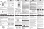
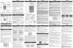
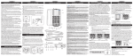
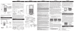
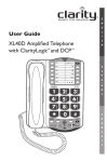
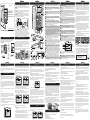
INSTALLING YOUR XL45
USER GUIDE
XL45™
XL45
TM
+++
ENTER
MENU
DELETE
Ampli�ed Telephone
with CID and DCP™
HOLD
RD/P
BOOST
Install the backup batteries (optional) by removing the battery cover as shown
in Figure 1. Connect your telephone as shown in Figure 2.
1 Connect one end of the phone cord into the (square) LINE port on
the back of the phone; connect the other end of the phone cord into your wall
telephone outlet.
2 Connect one end of the (curly) handset cord into the handset jack on
the left side of your base; connect the other end of the handset cord into the
bottom of the handset. Place handset in cradle.
port
3 Connect the DC adapter cord into the (round) DC 9V 500mA
on the back of your phone; plug the adapter into your wall electrical outlet.
When �nished, lift handset to test. If you hear a dial tone, your telephone is
ready for use. If not, check all connections again.
Figure 2
1
XL45
2
3
4
MENU
DELETE
5
6
OSA
VOLUME
TONE
1
2
3
ON
4
OFF
Talk
Keypad
Boost
Override
Missed
Call
Voice
Mail
ON
OFF
www.ActiveForever.com
1
Remove battery cover using a
thin object (like the tip of a pen)
to push down the tab shown by
the arrow above.
2
HOLD
RD/P
SPKR
FLASH
BOOST
7
3
OSA
VOLUME
TONE
1
If there is a power outage, the XL45 will maintain its full ampli�cation for up
to 48 hours with four AA alkaline backup batteries (not included).
The phone operates as a regular phone if there is no power or backup
batteries. In this case, the indicator lights, the loud ringer, the lighted keypad
and the ampli�cation will be disabled; you will still be able to make and receive
phone calls, but the extra ampli�cation will not be enganged. We recommend
installing batteries if you live in an area with frequent power outages.
2
3
4
8
9
13
11
14
12
10
15
16
RINGER SETTINGS
WALL MOUNTING YOUR XL45
CONTENTS & PARTS CHECKLIST
Your package includes all the items as shown here. If there is anything
missing, please contact our Customer Care Department immediately.
NOTE: PLEASE RETAIN A COPY OF PROOF OF PURCHASE
FOR YOUR RECORDS.
User Guide
™
XL45
XL45
TM
XL45™
ENTER
MENU
DELETE
ENTER
HOLD
RD/P
BOOST
SPKR
FLASH
OSA
VOLUME
TONE
1
Handset
2
3
4
Telephone line
cords
(one long cord and
one short cord)
MENU
HOLD
RD/P
BOOST
DELETE
FLASH
SPKR
OSA
VOLUME
TONE
1
2
3
4
+
1. Pull the handset hook out of the base and reverse its position so that the
hook points up and will hold the handset when you hang up. See Figure 3
2. Plug one end of the short �at telephone line cord into the jack marked
LINE located on the back of the telephone. Then run the cord through the
groove on the back of the phone. Insert the tabs of the mounting bracket into
the slots in the back of the phone. Push the mounting bracket in and down
�rmly until it snaps into place. See Figure 4.
3. Plug the �at telephone line cord into the wall plate jack, then align the
mounting bracket’s keyhole slots with the wall plate studs and slide the base of
the phone downward to secure it on the wall. See Figure 5.
User guide
-
TONE
VOLUME
18
19
ON OFF
20
22
21
SIDE VIEWS
23
Headset Outgoing Speech Neckloop
Lo Med Hi
24
ON
BACK VIEW
Talk
Keypad
OFF
Base unit
BOTTOM VIEW
BEDSHAKER
DC9V, 500mA
Boost
Override
Missed
Call
Voice
Mail
Tone/
Pulse
LINE
ON
T
OFF
P
DC adapter
Mounting bracket
Handset coil cord
Figure 3
Note: if you wish to return to the standby screens at any time, press the
MENU key.
CALLER ID OPERATIONS
Caller ID Operations
This is a service that is provided through your local telephone company.
This telephone will automatically display the incoming caller’s name and
number along with the date and time of the call. It will record up to 40
calls.
When there is a new incoming call the CID information will display on the
second ring. The �rst row on the display will have the caller’s ID (name).
If there is no information, the row will be blank. The second row displays
the incoming telephone number. If the number is longer than 11 digits, the
LCD will toggle the displayed number between the �rst 11 digits and the
remaining digits.
Note: The time and date will automatically register after receiving your
�rst call.
View CID
To view CID information press the MENU button. “View CID?” will
display with the options of “1 Yes 2 No”. Select “Yes” by pressing the one
(1) button and the most recent incoming call will be displayed. Press the
down arrow to view the next CID entry.
If there are no new calls the screen will display “No Calls”. You can also
access the CID records by pressing UP or DOWN keys from the standby
screen. See Figure 10.
Note: The display will time out and go to the standby screen if you have
not made a selection within 30 seconds.
Note: You can view the CID list by pressing either the UP or DOWN key
from standby (idle) mode.
™
XL45
Figure 10
26
27
12/18
To format and/or make a call from the CID entry, select the desired CID
entry and press the enter button. “Pick Format” will appear on screen �rst,
then “Press UP/DN” will appear. Using the arrow keys, choose the desired
format for the CID number, and press the Enter button. See Figure 11 and
Figure 12.
Note: A seven digit number will not display the area code. A 10 digit number
will display the area code without the one. The 11 digit number will display
the number, area code plus the one.
XL45
XL45
™
™
12/18
1:00 pm
PRESS UP/DN
18005644224
Figure 11
Figure 12
The next screens that will display are “Call Number?” and “1 Yes 2 No” with
your chosen formatted number. See Figure 13 and Figure 14.
If you select “Yes” the CID entry will then be dialed. If you select “No” the
CID will format and show the CID information.
NOTE: Saving a CID record to a MemDial button that is not blank will
overwrite the previously saved name/number without prompting.
™
XL45
Figure 13
28
™
XL45
12/18
1:00 pm
1 YES 2 NO
18005644224
Figure 14
To store any CID record to one of the memory keys, do the
following:
1. Pick the correct dialing format by following the steps above;
2. Press ENTER;
3. Choose “2” (No) when asked if you want to dial the number; the record
with the correct dialing format will be displayed on the screen.
4. Press and hold the memory key you wish to use for this record.
You are able to change the name of the record before storing it in the
memory keys. Press DEL to delete the displayed name, then use the keypad to
enter your custom name. (To introduce a space, press “1”).
The phone beeps, the display shows “Num Stored”, and the record is stored.
12/18
1:00 pm
VIEW MEM DIAL
1 YES 2 NO
Use the Delete button and delete MemDial 1 or name stored. Next, type in
the name of the number you wish to store. Then press the Enter button. Use
the Delete button to delete the number to be edited. If there is no number
stored type in the number you wish to store. Press Enter once again. The
number has now been stored into the M1 button. The menu will advance to
the next memory location – MemDial 2. (NOTE: To enter a space, press “1”).
Repeat these steps to program MemDial 2.
NOTE: To view the saved records under the Memory Dial buttons, you have
to press MENU, then DOWN key twice to arrive at “View MemdDial?”
submenu. Pressing the memory keys from standby (or while on a call) will
dial the numbers directly without further prompting (one-touch dial).
LANGUAGE
™
XL45
Figure 16
™
XL45
1:00 pm
LANGUAGE
3 FR
During Talk Mode
While on a call the screen will display a timer and volume level. If you make
the call, the screen will also display the number dialed.
If the Hold button is activated “Call on hold” will be displayed.
During Idle Mode
“Clarity XL45” will be displayed on screens during idle mode if the following
standby screens are not applicable.The number of calls will register to the
screen. Example: “1 Call”
“No Ph Line” will appear if no phone line is plugged in. If there is no DC
power “Batt Only” will appear and alternate with “No DC power”
While another phone is being used “Line In Use” will be displayed. If there is a
new voicemail “New VMail” will appear
Note: If there is a new CID, “New VMail screen” and the number of new
CID entries screen (example: “2 Calls”) will alternate.
This function ampli�es your speech so it becomes louder to the person on
the other end of the call. To enable this function, press and hold the BOOST/
OSA ON/OFF button for 3 seconds (see �gure 18). The phone beeps; the
function can be enabled/disabled while on a phone call or in standby mode.
To verify the function is active, lift the handset and check the light at the top
of the phone. If the light is orange, the function is active. To adjust the level of
ampli�cation for your voice, use the switch on the side of the phone labeled
Outgoing Speech Ampli�cation (OSA).You can choose between three levels:
Low, Med and High (see Figure 19).
To return to the default setting for your voice volume level, press and hold
the BOOST/OSA ON/OFF button again for 3 seconds.You will hear a beep
con�rming that the function is disabled. To verify, the light at the top of the
phone should not be orange when you are on a phone call.
NOTE: In order to experience the best audio quality for both parties during
a call, we recommend you turn on this function only if your voice is too quiet.
The screen brie�y displays “OSA ON” or “OSA OFF” when the changes are
made. OSA is not active in speakerphone mode.
12/18
Figure 17
Headset
Outgoind Speech Neckloop
Figure 19
Amplification (OSA)
1
2
3
1. While on a call, press the BOOST button to engage the ampli�er.
The XL45 has a BOOST button that controls the loudness of the receiver.
See Figure 6. Once the BOOST button is pressed, an extra level of
ampli�cation is added over the entire range of the Volume Control. During
a call, the BOOST button can toggle the Clarity Power function on or off
according to the user’s needs. The BOOST button will reset automatically
every time the phone is hung up for at least 5 seconds. The BOOST light
will illuminate (blue) while the BOOST function is activated.
Warning: Volume may be at a high level. To protect hearing, lower the
Clarity Power Volume Control before using the phone.
2. Adjust the VOLUME slider to achieve the desired sound level (up to
50dB of ampli�cation). The Clarity Power Volume Control adjusts the level
of volume the handset both in Boost or non-Boost modes. The volume
dial provides up to 16dB of volume before the BOOST button is activated.
Once the BOOST button is pressed, the XL45 will provide up to 50dB of
gain. See Figure 7.
3. Adjusting the TONE switch allows you to customize your hearing
experience. Since we all have different hearing preferences we suggest
exploring each setting to �nd the one most comfortable for you. These
four settings, along with our volume ampli�cation, are part of the Digital
Clarity Power (DCP™) technology. See Figure 8. The available settings are:
1- Low Frequency emphasis: best used to hear low pitched;
2 - Flat frequency response: best for hearing aid users;
3 - Clarity Power/High frequency emphasis response: best used to hear
high frequency sounds;
4 - Multi Band Compression with high frequency emphasis response:
best setting for speech intelligibility.
NOTE:The screen displays the volume and tone levels.
HOLD
4
Lo Med Hi
TECHNICAL INFORMATION
Amplified dB Level: 50dB/124dBSPL
Tone control range” Full range: 300 to 3000Hz using one slide control.
Dimensions
Size: 9 3/4” x 7” x 3 1/2” (24.765cm x 17.78cm x 8.89cm)
Weight: 2.52 lbs. (1.14 kg)
Power Requirements
AC Adapter: 9VDC, 500 mA
Batteries: 4 AA alkaline batteries (not included)
RD/P
BOOST
FLASH
SPKR
HOLD
RD/P
BOOST
FLASH
SPKR
VOICE
OSA
TONE
1
1
2
3
2
3
VOLUME
4
4
OSA
TONE
1
2
3
VOLUME
4
™
XL45
32
1:00 pm
12/18
33
MENU
SCREEN
VIEW
34
32TIME
indicator: the time is displayed if you have CID service (from
your local telephone service provider). The time is updated every time a
CID call is received.
indicator: indicates the level of charge in
33 Backup Battery Level
your backup batteries (if installed).
indicator: the date is displayed if you have CID service (from
34 DATE
your local telephone service provider).
Figure 6
Figure 7
Figure 8
Boost Override
On the bottom of the XL45, there is a Boost Override switch. When
this is set to “ON” the Boost function is automatically enabled
every time the phone is picked up. In standard use, when the Boost
Override switch is set to “OFF” the Boost function will turn off after
the phone is hung up. Setting this switch to “ON” is suggested if all
the users of the phone need the ampli�cation. Setting this switch
to “OFF” is useful when people with varying hearing ability use the
phone. See Figure 9.
Figure 9
CAUTION:VOLUME MAY BE LOUD.
PROCEED WITH CARE.
Boost
Override
ON
OFF
SECTION 11
TROUBLESHOOTING
Figure 18
The user will have the option to select English, French or Spanish. Press the
MENU button and press the down arrow until “Language” appears. Press 1
(one) for English, press 2 (two) for Spanish, press 3 (three) for French. See
Figure 16 and Figure 17.
BOOST FUNCTION - AMPLIFY INCOMING
SOUNDS
SECTION 10
OUTGOING SPEECH AMPLIFICATION (OSA)
MemDial 1 or the saved name and number will appear. (To go to the next
Mem Dial location press the DOWN arrow)
12/18
: press the keys to increase/decrease the
volume of the incoming ring.
switch: use this switch to turn the ringer on
20 (Ringer) ON/OFF
or off. When the switch is set to OFF, the light at the top of the phone
lights up RED .
21 Headset port: insert a standard headset (2.5mm plug) to use instead
of handset.
22 Outgoing Speech Amplification (OSA) switch
: use the switch
to set the level of the outgoing speech ampli�cation level. To enable/
disable the OSA switch, press and hold the BOOST/OSA button for 3
seconds (see OSA section).
23 Neckloop port: insert a standard neckloop (mono, 3.5mm plug) to
use with your T-coil equipped hearing aid. We recommend the Clarity
CE30 neckloop.
24Talk Keypad
switch: set to ON if you wish to hear the numeric keys
pressed during dialing - both in handset and speakerphone modes. NOTE:
“star” and “pound” keys are not spoken.
25 Boost Override
switch: set to ON if you wish for the BOOST
function to be enabled at the beginning of all calls.
26 Missed Call
switch: set to ON if you wish to have the Missed Call
light enabled.
27 Voice Mail
switch: set to ON if you wish for the light at the top of
the phone to turn green when you have a voice mail (service from your
phone service provider).
28 Tone/Pulse switch: set this switch to the desired dialing method.
port: insert the optional bedshaker (sold separately)
29 BEDSHAKER
will vibrate to indicate incoming rings.
30 LINE: see INSTALLING YOUR XL45
section.
31 POWER PORT (9V,500mA):
see INSTALLING YOUR XL45
section.
STANDBY SCREENS
™
XL45
1:00 pm
LANGUAGE
1 EN 2 SP
19 (Ringer) Volume +/-
SECTION 9
Phone numbers can be stored into the phones memory to enable one
button dialing. The phone directory allows space for four (4) different phone
numbers.
It is important to not store 911 into your phone. This will prevent
inadvertently calling an emergency call center. Only store emergency numbers
such as a doctor, hospital, the local �re department or local police station
numbers.
Programming/Editing the Memory Dial Buttons
This feature will allow the user to program or edit numbers in the 4 (four)
Memory Dial locations or make changes to the current programmed numbers.
Press the MENU button then press the down arrow to the “View MemDial”
screen. See Figure 15. You will have the option of choosing “Yes” or “No”.
Select “Yes” by pressing the one (1) button.
Figure 15
12/18
1:00 pm
CALL NUMBER?
18005644224
31
MEMORY STORAGE
Formatting and Calling from CID
12/18
1:00 pm
PICK FORMAT
18005644224
MENU screen: press to show the CID information, check the
memory records, get information about the volume and tone levels, etc.
2 ENTER button: press to con�rm choices listed on the screen.
: press to navigate through the menu
3 Arrow buttons (UP/DOWN)
choices, CID and memory records.
button: press to access the menu for CID/memory checking,
4 MENU
language setup.
5 DELETE
button: press to delete CID/memory records, and to edit
names/numbers.
6 MEMORY
buttons: for saved numbers (see MEMORY STORAGE).
7 SPKR (Speaker) Button: press SPKR to engage the speakerphone
function; press again to turn the feature off.
Button: use this button to engage the Call Waiting/Call
8 FLASH
Waiting Caller ID function (feature provided by local phone company).
Slider: move to right or left in order to increase or
9 VOLUME
decrease the volume of the incoming voice.
10 BOOST/OSA
Button: press BOOST to engage the extra
ampli�cation. In BOOST OFF mode, the phone has a volume range of up
to 16dB of ampli�cation. In BOOST ON mode, the phone has a volume
range of up to 50dB of ampli�cation. When active, the BOOST button is
backlit. Press BOOST again to turn off the extra ampli�cation. Press and
hold the button for 3 seconds to engage the OSA function (to enhance
the level of your voice). See OSA section for details.
NOTE: when OSA is enabled, the light at the top of the phone turns
orange when the phone is in a call.
11 RD/P (Redial/Pause) Button: use this button to redial the last
number dialed (up to 32 digits). When in programming mode, press this
button to insert a 2-second pause.
12TONE
Switch: use this switch to pick one of the 4 tone setting
available.
13 HOLD
Button: during a call, use this button to put the call on hold;
press the button again to release the call from hold.
14 Missed Call
light: light turns on when there was an unanswered call.
(Active when Missed Call switch is ON - located on bottom of phone).
15 Visual Ringer Lights: lights turn on and off when the phone rings.
16 Low Battery Indicator: light turns on when the backup batteries are
low.
17 Voice Mail/Ringer/VOICE
light: a. Light turns on GREEN when
there is a voicemail left with your voicemail feature (from local phone
company). b. Light turns RED when the ringer switch is in the OFF
position. c. Light turns ORANGE when the VOICE feature is active.
18 (Ringer) TONE
: press this button to choose the desired incoming
ring tonality. Choose one of the six (6) availble ring tones to select the
most favorable ringer.
SECTION 8
CALLER ID OPERATIONS
To switch from one main menu option to the next, press the down arrow.
1:00
VIEW CID?
1 YES 2 NO
25
SECTION 7
There are three main menu options on the XL45:
CID, Memory Dial, and Language.
pm
Figure 5
Figure 4
SECTION 6
MENU OPTIONS
30
29
SECTION 5
FEATURE LIST AND OVERVIEW
1
17
™
ENTER
SECTION 4
FEATURE LIST AND OVERVIEW
FEATURE LIST AND OVERVIEW
Figure 1
SPKR
FLASH
SECTION 3
SECTION 2
SECTION 1
TROUBLESHOOTING
Static On The Line
No Dial Tone/Phone Will Not Operate
1. Check all phone cords and connections. Make sure they are plugged in
securely.
2. Plug unit into a different phone jack to help determine if the
with the phone or the phone jack.
dif�culty is
3. Switch out handset or telephone line cords.
4. Disconnect any other equipment that may be attached to the phone.
Unable To Dial Out
1. Make sure TONE/PULSE switch is set correctly.
2. Phone may be at the end of a long line of phones (loop). Phone may not be
getting enough power from the phone line. It may be necessary to wait for a
few seconds after lifting the handset to begin dialing.
3. The XL45 is not compatible with Digital PBX Systems. If a standard, single
line phone works on the system, your XL45 should also.
4. There is an advanced computer running inside the XL45. Sometimes after
the handset is picked up, it will take a little less than a second to engage the
phone. Since it is not immediate, if you dial a number before the computer
engages, it will not receive the entire phone number that is dialed.
The Person On The Other End Cannot Hear You
1. Too many phones or phone devices on the line may effect your
phone’s transmission. As a guideline, more than �ve (5) phones or phone
devices may overload the phone line. Disconnect one (1) or two (2) devices
to see if that eliminates the problem. If not, contact your local phone
company for load guidelines.
2. You may not be speaking directly into the transmitter. Always speak
directly into the mouth piece in your normal tone of voice.
1. Your phone may be located near a touch lamp, microwave, refrigerator
or other household appliances. Try relocating your phone to another area.
2. A cordless phone on your line may cause static. Try disconnecting the
cordless phone. This may eliminate the problem.
3. Extra devices attached to the telephone, such as CID units and
answering machines may cause static. Disconnecting the devices may
eliminate the problem.
4. If there is also a DSL service in the home, this will cause interference
on the line. That interference is then ampli�ed by the phone, causing a less
than optimal quality of conversation. Install the phone line �lter provided
by the DSL service provider to reduce the amount of interference on the
line.
Interference
1. Check cords and connections. Frayed or poorly connected cords
can cause interference. Swap cords if necessary.
2. A RFI (Radio Frequency Interference) �lter can be placed on the
line to help minimize or eliminate radio or CB transmissions. Try
relocating the telephone to another area.
Unable to Access Automated Systems
Automated systems used by banks, long distance voice mail and other
applications require that a phone be set to “tone” dialing. Check the switch
on the back of the phone labeled “T/P” and set to “T.” This will enable the
phone to be compatible with these automated systems. Compatibility
If No Power is being Supplied to the Phone.
Unable To Hear Phone Ringer
1. If the power goes out, or the AC Adapter is not properly connected to
the phone, several functions of the phone will not work. The ampli�cation,
extra loud ringer, and the lighted keypad will not function properly.
1. Too many phone or phone devices on a line may cause your phone to not
ring. Disconnect one (1) or two (2) of the devices to see if the problem is
eliminated. If not, contact your local phone company for load guide lines.
2. The phone will drain the backup batteries very quickly. This will cause
the need for the batteries to be changed frequently and the Low Battery
indicator light to constantly illuminate.
2. If power is not being supplied to the phone, the extra loud ringer will not
work.
Do I Need to Install Batteries?
3. Check the Ringer ON/OFF switch to see if the ringer is off. If yes, move it
to the ON position.
Volume Control Does Not Work
1. BOOST must be activated to turn on the additional ampli�cation.
2. Check power connections. BOOST will not work without power or
backup batteries.
Batteries are optional. They provide backup in case of a power outage.
They are recommended in areas of frequent power outages. This phone
uses four (4) alkaline batteries. They will sustain the following functions:
ampli�cation.
SECTION 12
IMPORTANT SAFETY INSTRUCTIONS
When using your telephone equipment, basic safety
precautions should always be followed to reduce the risk
of �re, electric shock and injury to persons including the
following:
1. Read and understand all instructions.
2. Follow all warnings and instructions marked on the
telephone.
3. Do not use this telephone near a bathtub, wash basin,
kitchen sink or laundry tub, in a wet basement, near a
swimming pool or any where else there is water.
4. Avoid using a telephone (other than a cordless type)
during a storm. There may be a remote risk of electrical
shock from lightning.
5. Do not use the telephone to report a gas leak in the
vicinity of the leak.
6. Unplug this telephone from the wall outlets before
cleaning. Do not use liquid cleaners or aerosol cleaners on
the telephone. Use a damp cloth for cleaning.
7. Place this telephone on a stable surface. Serious damage
and/or injury may result if the telephone falls.
8. Do not cover the slots and openings on this telephone.
This telephone should never be placed near or over a
radiator or heat register. This telephone should not be
placed in a built-in installation unless proper ventilation is
provided.
9. Operate this telephone using the electrical voltage as
stated on the base unit or the owner’s manual. If you are
not sure of the voltage in your home, consult your dealer or
local power company.
10. Do not place anything on the power cord. Install the
telephone where no one will step or trip on the cord.
11. Do not overload wall outlets or extension cords as this
can increase the risk of �re or electrical shock.
12. Never push any objects through the slots in the
telephone. They can touch dangerous voltage points or
short out parts that could result in a risk of �re or electrical
shock. Never spill liquid of any kind on the telephone.
SECTION 13
IMPORTANT SAFETY INSTRUCTIONS
13. To reduce the risk of electrical shock, do not take this
phone apart. Opening or removing covers may expose you to
dangerous voltages or other risks. Incorrect reassembly can
cause electric shock when the appliance is subsequently used.
14. Unplug this product from the wall outlet and refer
servicing to the manufacturer under the following conditions:
when the power supply cord or plug is frayed or damaged.;
if liquid has been spilled into the product; if the telephone
has been exposed to rain or water; if the telephone does
not operate normally by following the operating instructions.
adjust onlythose controls that are covered by the operating
instructions. Improper adjustment may require extensive work
by a quali�ed technician to restore the telephone to normal
operation.; if the telephone has been dropped or the case has
been damaged; if the telephone exhibits a distinct change in
performance.
15. Never install telephone wiring during a lightning storm.
16. Never install telephone jacks in wet locations unless the
jack is specifcally designed for wet locations.
17. Never touch uninsulated telephone wires or terminals
unless the tele phone line has been disconnected at the
network interface.
18. Use caution when installing or modifying telephone lines.
BATTERY SAFETY INFORMATION
Dispose of used batteries according to the
instructions.
1. Do not dispose of the battery in a �re as it may explode.
Check with local codes for possible special disposal
instructions.
2. Do not open or mutilate the battery. Released electrolyte
is corrosive and may cause damage to the eyes and skin. It
may be toxic if swallowed.
3. Exercise care in handling batteries in order not to short
the battery with conducting materials such as rings, bracelets
and keys. The battery or conduction material may overheat
and cause burns.
CLARITYLOGIC
INTRODUCTION TO CLARITYLOGIC
ClarityLogic is the name of our simpli�ed and easy to use
customer support service. While talking to a Clarity representative,
the telephone sends information such as its model name and
settings to Clarity. The representative is immediately aware of
the type and current settings of the phone. This will allow any
troubleshooting call to be quick and simple, helping you �nd exactly
what you are looking for.
For your convenience, Clarity has pre-programmed the customer
support number into M1 of the phone. If you do not wish to
have this number stored in your phone, any new number can be
programmed to that button.To do this, follow the directions in the
MEMORY STORAAGE section of the User Guide.
NOTE: ClarityLogic has been designed to work with plain old telephony
service (POTS). If your phone service is provided by a broadband service
provider, ClarityLogic may not work.
ONLY CLARITYLOGIC MAY BE DISABLED. ALL OTHER FEATURES WORK
AS DESCRIBED IN THIS USER GUIDE.
SUBSCRIPTION DATA AND PRIVACY POLICY
Your device will automatically send Clarity various types of information as part of
the Clarity services, which may include the telephone number associated with your
device. This information may be combined with account and other information we
have on record regarding you or your device or may be transmitted to us by your
device. To assist with remote diagnostics and other customer services functions,
your device may also regularly send us certain information associated with your
device, including software and hardware settings, the phonebook, caller ID history
and other information you have stored on the device. All of such information,
together with other information that we have on record regarding you and your
device is collectively referred to as the “Subscription Data”. We use this information
to diagnose and troubleshoot any device issues as well as to provide you with the
Services.
You agree that Clarity and its subsidiaries, af�liates, partners, suppliers, and agents
(collectively, “Af�liates”) may collect, store, access, disclose, transmit, process, and
otherwise use your Subscription Data to provide you with the Clarity services,
address your requests, provide technical support, process transactions for your
account, and otherwise use such Subscription Data in accordance with Clarity’s
privacy policy (http://www.clarityproducts.com/privacy.asp), which is hereby
incorporated by reference. Clarity may also provide or enable certain Services
through your Device that rely upon location information. In order to provide such
Services, Clarity and its Af�liates may collect, store, access, disclose, transmit, process,
and otherwise use your location data (including real time geographic Information) in
accordance with Clarity’s privacy policy.
SECTION 14
REGULATORY COMPLIANCE
Part 68 of FCC Rules Information
a) This equipment complies with Part 68 of the FCC
rules and the requirements adopted by the ACTA. On the
bottom of this equipment is a label that contains, among
other information, a product identi�er in the format
US:AAAEQ##TXXXX. If requested, this number must be
provided to the telephone company.
b) A plug and jack used to connect this equipment to the
premises wiring and telephone network must comply with
the applicable FCC Part 68 rules and requirements adopted
by the ACTA. A compliant telephone cord and modular plug,
RJ11C USOC, is provided with this product. It is designed
to be connected to a compatible modular jack that is also
compliant. See installation instructions for details.
c) The REN is used to determine the number of devices
that may be connected to a telephone line. Excessive RENs
on a telephone line may result in the devices not ringing in
response to an incoming call. In most but not all areas, the
sum of RENs should not exceed �ve (5.0). To be certain of
the number of devices that may be connected to a line, as
determined
by the total RENs, contact the local telephone company.
For products approved after July 23, 2001, the REN for this
pro-duct is part of the product identi�er that has the format
US:AAAEQ##TXXXX.
The digits represented by ## are the REN without a decimal
point (e.g., 03 is a REN of 0.3). For earlier products, the REN
is separately shown on the label.
d) If this telephone equipment causes harm to the telephone
network, the telephone company will notify you in advance
that temporary discontinuance of service may be required.
But if advance notice isn’t practical, the telephone company
will notify the customer as soon as possible. Also, you will be
advised of your right to �le a complaint with the FCC if you
believe it is necessary.
SECTION 18
WARRANTY SERVICE INFORMATION
The following warranty and service information applies only
to products purchased and used in the U.S. and Canada. For
warranty information in other countries, please contact your
local retailer or distributor.
Limited Warranty : Clarity, a division of Plantronics, Inc.
(“Clarity”) warrants to the original consumer purchaser
that, except for limitations and exclusions set forth below,
this product shall be free from defects in materials and
workmanship for a period of one (1) year from the date
of original purchase (“Warranty Period”). The obligation of
Clarity under this warranty shall be at Clarity’s option, without
charge, of any part or unit that proves to be defective in
material or workmanship during the Warranty Period.
Exclusions from Warranty: This warranty applies only to
defects in factory materials and factory workmanship. Any
condition caused by accident, abuse, misuse or improper
operation, violation of instructions furnished by Clarity,
destruction or alteration, improper electrical voltages or
currents, or repair or maintenance attempted by anyone other
than Clarity or an authorized service center, is not a defect
covered by this warranty. Telephone companies manufacture
different types of equipment and Clarity does not warrant that
its equipment is compatible with the equipment of a particular
phone company.
Implied Warranties: Under state law, you may be entitled
to the bene�t of certain implied warranties. These implied
warranties will continue in force only during the warranty
period. Some states do allow limitations on how long an
implied warranty lasts, so the above limitation may not apply
to you.
Incidental or Consequential Damages : Neither
Clarity nor your retail dealer or selling distributors has any
responsibility for any incidental or consequential damages
including without limitation, commercial loss or pro�t,
or for any incidental expenses, expenses, loss of time, or
inconvenience. Some states do not allow exclusion or
limitation of incidental or consequential damage, so the above
limitation or exclusion may not apply to you.
SECTION 15
REGULATORY COMPLIANCE
Part 68 of FCC Rules Information
e) The telephone company may make changes in its facilities,
equipment, operations or procedures that could affect the
operation of the equipment. If this happens the telephone
company will provide advance notice in order for you to make
necessary modi�cations to maintain uninterrupted service.
f) If trouble is experienced with this telephone equipment, for
repair or warranty information, please contact ActiveForever,
1-800-377-8033. If the equipment is causing harm to the
telephone network, the telephone company may request that
you disconnect the equipment until the problem is resolved.
g) This telephone equipment is not intended to be repaired
and it contains no repairable parts. Opening the equipment
or any attempt to perform repairs will void the warranty.
h) Connection to party line service is subject to state tariffs.
Contact the state public utility commission, public service
commission or corporation commission for information.
i) If your home has specially wired alarm equipment
connected to the telephone line, ensure the installation of this
telephone equipment does not disable your alarm equipment.
If you have questions about what will disable alarm equipment,
consult your telephone company or a quali�ed installer.
j) This telephone equipment is hearing aid compatible.
Customer-Owned Coin/Credit Card Phones:
To comply with state tariffs, the telephone company must
be given noti�cation prior to connection. In some states, the
state public utility commission, public service commission
or corporation commission must give prior approval of
connection.
SECTION 16
REGULATORY COMPLIANCE
Part 15 of FCC Rules Information
This device complies with Part 15 of the FCC Rules.
Operation is subject to the following two conditions: (1) This
device may not cause harmful interference, and (2) this device
must accept any interference received, including interference
that may cause undesired operation.
Your equipment has been tested and found tocomply with
the limits of a Class B digital device, pursuant to Part 15 of
FCC rules. These limits are designed to provide reasonable
protection against harmful interference in residential
installation.
This equipment generates, uses and can radiate radio
frequency energy and, if not installed and used in accordance
with the instructions, may cause harmful interference to
radio communications. However, there is no guarantee that
interference will not occur in a particular installation; if this
equipment does cause harmful interference to radio or
television reception, which can be determined by turning the
equipment off and on, you are encouraged to try
to correct the interference by one of the following measures:
1. Where it can be done safely, reorient the receiving
television or radio antenna.
2. To the extent possible, relocate the television, radio or
other receiver with respect to the telephone equipment. (This
increases the separation between the telephone equipment
and the receiver.)
3. Connect the telephone equipment into an outlet on a
circuit different from that to which the television, radio, or
other receiver is connected.
4. Consult the dealer or an experienced Radio/TV Technician
for help.
CAUTION:
Changes or modi�cations not expressly
approved by the manufacturer responsible for compliance
could void the user’s authority to operate the equipment.
SECTION 17
REGULATORY COMPLIANCE
Industry Canada Technical Specifications
This product meets the applicable Industry Canada
technical specifications.
Before installing this equipment, users should ensure that it
is per- missible to be connected to the facilities of the local
telecommunications company. The equipment must also be
installed using an acceptable method of connection. In some
cases, the company’s inside wiring
associated with a single line individual service may be extended
by means of a certi�ed connector assembly (telephone
extension cord). The customer should be aware that compliance
with the above conditions may not prevent degradation of
service in some situations. Repairs to certi�ed equipment
should be made by an authorized Canadian maintenance facility
designated by the supplier.
Any repairs or alterations made by the user to this equipment,
or equipment malfunctions, may give the telecommunications
company cause to request the user to disconnect the
equipment.
Users should ensure for their own protection that the electrical
ground connections of the power utility, tele-phone lines and
internal metallic water pipe system, if present, are connected
together. This precaution may be particularly important in rural
areas.
CAUTION:
Users should not attempt to make such
connections themselves, but should contact the appropriate
electrical inspection authority, or electrician, as appropriate.
The Ringer Equivalence Number is an indication of the
maximum number of terminals allowed to be connected to a
telephone interface. The termination on an interface may consist
of any combination of devices subject only to the requirement
that the sum of the Ringer Equivalence Numbers of all the
devices does not exceed �ve.
(The term “IC:” before the certi�cation/registration number
only signi�es that the Industry Canada technical speci�cations
were met.)