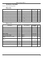
1
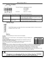
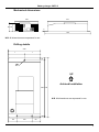
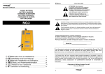
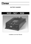
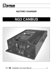
CHFC-3
Your Power Solutions Specialists
HIGH FREQUENCY BATTERY CHARGER
BATTERY CHARGER
Installation and User Manual
Battery charger CHFC-3
ATTENTION: To reduce the risk of
electric shock, do not remove cover.
Refer servicing to qualified service personnel.
Disconnect the mains supply before connecting
or disconnecting the links to the battery.
Read the Instruction Manual carefully
before use. Verify that the selected
charge curve is suitable for the type
of battery You have to re-charge.
Explanation of Graphical Symbols
The lightning flash with arrowhead symbol, within an equilateral triangle, is intended to alert
the user to the presence of uninsulated “dangerous voltage” within the equipment’s
enclosure; that may be of sufficient magnitude to constitute a risk of electric shock to
persons.
The exclamation point within an equilateral triangle is intended to alert the user to the
presence of important operating and maintenance (servicing) instructions in the literature
accompanying the equipment.
This product is covered by warranty.
The relative warranty certificate is attached to the Instructions Manual.
If the Manual is not provided with this certificate, please ask your retailer for a copy.
For further references, please write the serial number in the proper space:
Serial No. _____________________
2
Battery charger CHFC-3
Installation and safety instructions
Battery charger CHFC-3 has been designed to provide safety and reliable. It is necessary to observe the
following precautions in order to avoid damage to persons and to the battery charger:
•
Read the installation instructions contained in this Manual carefully. For further information put the
Manual in a proper place.
•
Fix the battery charger to a stable surface through the appropriate holes inserted on the fixing
flanges. In case of installation on a vehicle it is advisable to use antivibration supports.
•
Preferably the charger should be installed in the vertical position with fans facing up. The horizontal
installation is allowed. Never install in the vertical position with fans facing down.
•
Ensure all ventilation ports are not obstructed, to avoid the overheating. Do not put the battery
charger near heat sources. Make sure that free space around the battery charger is sufficient to
provide adequate ventilation and an easy access to cables sockets.
•
Protect the battery charger from ingress of water. Do not pour liquids inside the case.
•
Verify that the available supply voltage corresponds to the voltage that is stated on the battery
charger name plate. In case of doubt, consult a retailer or local Electric Supply Authority.
•
For safety and electromagnetic compatibility, the battery charger has a 3-prong plug as a safety
feature, and it will only fit into an earthed outlet. If you can not plug it in, chances are you have an
older, non-earthed outlet; contact an electrician to have the outlet replaced. Do not use an adapter to
defeat the earthing.
•
To avoid damaging the power cord, do not put anything on it or place it where it will be walked on. If
the cord becomes damaged or frayed, replace it immediately.
•
If you are using an extension cord or power strip, make sure that the total of the amperes required by
all the equipment on the extension is less than the extension’s rating.
•
Disconnect the mains supply before connecting or disconnecting the links to the battery.
•
To recharge Lead Acid batteries: WARNING: Explosive Gas – Avoid flames and sparks. The battery
must be positioned in a correctly cooled place.
•
Do not use to charge batteries installed on board of thermal engine cars.
•
Avoid recharging of non-rechargeable batteries.
•
Verify that the nominal voltage of the battery to be re-charged corresponds to the voltage stated on
the battery charger name plate.
•
Verify that the selected charging curve is suitable for the type of battery to be re-charged. In case of
doubt, consult Your retailer. ZIVAN S.r.l. will not accept any responsibility in case of mistaken choice
of the charging curve that may cause irreversible damage to the battery.
•
In order to avoid voltage drop, thereby assuring 100% charge at the battery, the output cables must
be as short as possible, and the diameter must be adequate for the output current.
•
In the case of thermal compensation of the battery voltage, it is necessary to place the thermal
sensor in the area of highest battery temperature.
•
Do not try to service the battery charger yourself. Opening the cover may expose you to shocks or
other hazards.
•
If the battery charger does not work correctly or if it has been damaged, unplugged it immediately
from the supply socket and from the battery socket and contact a retailer.
3
Battery charger CHFC-3
Operating principle
The battery charger considerably affects battery life and performances, which is the main part of every
electric vehicle.
A non controlled traditional battery charger (rectifier) provides a simple direct AC/DC conversion.
Disadvantages of this solution are:
• Low efficiency
• Large physical size
• Long charge times
• Charge depends on changes in the mains supply (with
overcharge danger in the final charge phase)
i
AC
v
Battery
DC
In modern battery chargers these disadvantages are solved with an indirect AC/DC conversion, by
passing through an intermediate DC/DC conversion.
This is the usual method of operation for the
i
SMPS (Switching Mode Power Supply) at
high power. This solution gives a good
DC
AC
performance for minimum costs and physical
Battery
v
dimensions using switches more faster and
DC
DC
powerful (modern technology).
The main advantages of this solution are:
• High efficiency
• Reduced dimensions
• Short charge times
• Charge independent from the changes of the mains supply
• Electronic control that provides the desired charge curve
The advent of electrical problems (due to commutation) has imposed the introduction of adequate filtering
to satisfy requirements of EMC 89/336/EEC directive for electromagnetic compatibility.
Block Diagram
L
E
N
F1
F2
EMI
FILTER
RECTIFIER
AND
FILTER
POWER
RECTIFIER
CONTROL
AND
FILTER
LOGIC
STAGE
RECTIFIER
AND
FILTER
EMI
FILTER
4
Battery charger CHFC-3
LED Indicator
100%
80%
80%
RED LED shows that the battery is in the initial charging phase.
YELLOW LED shows that the battery charger has reached 80% of charge.
GREEN LED shows that the battery has reached 100% of charge.
START
Further information can be found in the description of the Charging Curve.
Example: RED LED on with brief blinks indicates a constant tension phase.
Alarms (Two-tone audible message)
An two-tone audible message and the flashing LED shows that an Alarm situation has occurred:
Condition
Alarm Type
Audible message +
Battery Presence
Battery disconnected or not in conformity. (Verify the
connection and the nominal voltage).
Thermal Sensor
The thermal sensor is disconnected during the recharge or it is out working range. (Verify the
connection of the sensor and measure the
temperature of the battery).
Timeout
Phase 1 and/or Phase 2 have a duration in excess of
the maximal allowed. (Verify the battery capacity).
Battery Current
Loss of output Current control. (Failure of the control
logic).
Battery Voltage
Loss of output Voltage control. (Battery disconnected
or failure of the control logic).
Selection
An unavailable configuration has been selected
(Verify the selector’s position)
Thermal
Overheating of semiconductors. (Verify the fan
operation).
RED flash
Audible message +
YELLOW flash
Audible message +
GREEN flash
Audible message +
RED-YELLOW flash
Audible message +
RED-GREEN flash
Audible message +
YELLOW -GREEN flash
Audible message +
RED-YELLOW-GREEN
flash
Description (Action)
When there is an alarm the battery charger stops supplying current.
Thermal Sensor and/or External Indicator
Thermal Sensor and External Indicator are Options that have to be connected to the 5 poles socket 180°.
Unless otherwise stated, the compensation of the Battery Voltage in
function of the temperature of the Thermal Sensor is of -5mV/°C for
battery cell.
The control range of the Thermal Sensor goes from -20°C to +50°C.
The External Indicator reflects exactly the LED Indicator which is placed
on the equipment.
Further information can be found in the description of the Charging
Curve.
5
Battery charger CHFC-3
Auxiliary Contacts
AUX1
NC
C
NO
AUX2
NC
C
NO
Technical Features: changeovers contacts
0,3A 125VAC
0,3A 110VDC
1A 30VDC
Connector:
faston 6,3 × 0,8 mm
Unless otherwise stated, the auxiliary contacts provide the following functions:
Section
AUX1
Function
Mains Presence
AUX2
End of charge or
Trickle Phase
Description
When the equipment is switched on, the contact
Normally Open (NO) CLOSES and instead the contact
Normally Closed (NC) OPENS.
When the Stop Phase or the No Stop Phase is reached,
the contact Normally Open (NO) CLOSES and instead
the contact Normally Closed (NC) OPENS.
LED Bar Graph
100%
The LED Bar Graph is an Option that shows a percentage indication of output current in
comparison with its max. value
50%
CURRENT
Battery
A battery is characterised by two sizes: tension and capacity.
Tension:
Each element has a nominal tension, which depends on the type of battery (no
matter what size).
In order to reach higher tension, many elements are connected in series, so
creating a “BATTERY” of elements.
The number of elements is calculated by dividing the nominal tension of the
battery for the tension of each single element in the table:
Type
Pb
NiCd
NiMH
NiZn
Nominal
Tension
2 V/cell
1,2 V/cell
1,2 V/cell
1,714 V/cell
Capacity:
It is the quantity of electric charge that the batteries can supply to an external circuit before the tension
decreases under the final limit value and it is obtained by multiplying the intensity of the discharging
current I, expressed in ampere (A), for the discharging time t expressed in hours (h): C = I x t
The traction battery capacity is normally referred to the discharging system of 5h: C5 = I x 5h.
The capacity values that can be recharged by the battery chargers can be found in the description of the
Charging Curve (this value is not present in the curves able to charge any capacity).
:
This device is in conformity with the Low Voltage directive 73/23/EEC
and EMC directive 89/336/EEC and their further modifications.
6
Battery charger CHFC-3
Mechanical dimensions
370
220
90 78
6
430
N.B. All dimensions are expressed in mm.
Drilling details
220
=
=
18
6
UP
Advised Installation
399 430
N.B. All dimensions are expressed in mm.
13
60
100
60
7
Battery charger CHFC-3
TECHNICAL FEATURES
Ta=25°C unless otherwise specified
Mains side
Description
Supply Voltage
Frequency
Absorbed Maximum Current
Inrush Current
Symbol
Test Condition
Value and/or
Range
Unit
Vin
-
230 ± 10%
Veff
f
-
50 ÷ 60
Hz
20
Aeff
Iinmax
< 1,35
A
cosϕ
P = Pmax
0,68
-
Absorbed Minimum Power
Pinmin
End of charge
<5
W
Absorbed Maximum Power
Pinmax
P = Pmax
3
kW
Power Factor
-
P = Pmax
Vin = 230Veff
Battery side
Description
Symbol
Test Condition
Value and/or
Range
Unit
Output current
I
-
See curve
-
Maximum output current
I1
Phase 1
See curve
A
Output current ripple
-
I = I1
< 5%
-
Absorbed current
Ia
Equipment turned off
Output voltage
U
Constant output voltage
U1
Thermal compensation of output
voltage
dU1/dT
Operating range of Temperature
Sensor
∆T
Output voltage ripple
Maximum power supplied
Output capacity
< 0,5
mA
See curve
-
Phase 2
See curve
V
Phase 2
-5
mV /
(°C·cell)
from -20
°C
-
-
to +50
Pmax
C
U = U1
< 1%
-
U = U1, I = I1
2550
W
Depend on the
model (>0,2)
mF
-
8
Battery charger CHFC-3
General
Description
Symbol
Test Condition
Value and/or
Range
Unit
Operating range of temperature
∆T
-
from -20 to +50
°C
Maximum relative humidity
RH
-
90%
-
Switching frequency
fc
-
30 ± 5%
kHz
Efficiency
η
> 85%
-
Maximum size
At each operation
condition
a×b×c
Without connecting
cable
430×220×90
mm
Weight
-
Without connecting
cable
5,5
kg
Enclosure class
-
IP20
-
-
Protection and Safety
Description
Symbol
Test Condition
Value and/or
Range
Unit
Insulation
-
Mains to Battery side
1250
VAC
Insulation
-
Mains side to Earth
500
VDC
Insulation
-
Battery side to Earth
500
VDC
Leakage current
IL
Supplied equipment
<3
mA
Input fuse
F1
Inside the equipment
20
A
Output fuse
F2
Inside the equipment
about 1,2×I1
A
1,5
V/cell
See curve
V
Protection
provided by
fuse F2
-
100
°C
Minimum output voltage of operation
(Battery Detector)
Maximum output voltage
Um
Equipment turn on
Phase 3 (IUIa - IUIUo)
Reverse output polarity
-
At the connection to the
Battery
Thermal protection of semiconductors
(Temperature of Thermal Alarm)
-
Ta=55°C
Safety Requirements (Rules)
-
EN60335-1, EN60335-2-29
-
-
EMC Requirements (Rules)
-
EN55014-1, EN61000-3-3
EN55014-2, EN61000-4-2
EN61000-4-4, EN61000-4-5
EN61000-4-6, EN61000-4-11
-
-
1573 LAPERRIERE AVENUE OTTAWA ON 1Z 7T3
OTTAWA
Tel: 613-725-3704
Fax: 613-725-0490
Your Power Solutions Specialists
TORONTO:
Tel: 613-725-3704
Fax: 613-725-0490
VANCOUVER:
Tel: 604-736-4922
Fax: 604-736-1074
A DIVISION OF CANTEC REPRESENTATIVES