1
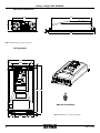
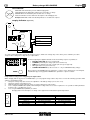
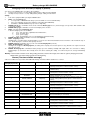
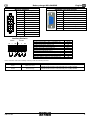
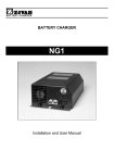
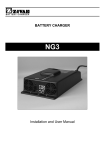
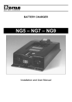
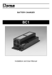
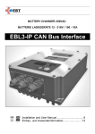
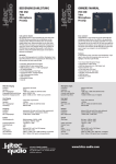
B AT T E R Y C H AR G E R
BATTERY CHARGER
NG3 CANBUS
Installation and User Manual ...................................4
Battery charger NG3 CANBUS
Mechanical dimension
220
368
100 95
7
430
N.B. All dimensions are expressed in mm.
Drilling details
220
40
140
40
15
401
430
UP
Advised Installation
60
2
100
60
14
N.B. All dimensions are expressed in mm.
D01737-01
Battery Charger NG3 CANBUS
Mechanical dimension with Air Pump
220
445
210
540
N.B. All dimensions are expressed in mm.
Drilling details with Air Pump
Ø6.5
505
540
UP
Advised Installation
Ø6.5
N.B. All dimensions are expressed in mm.
D01737-01
3
English
Battery charger NG3 CANBUS
ATTENTION: To reduce the risk of
electric shock, do not remove cover.
Refer servicing to qualified service personnel.
Disconnect the mains supply before connecting
or disconnecting the links to the battery.
Read the Instruction Manual carefully
before use. Verify that the selected
charge curve is suitable for the type
of battery You have to re-charge.
Explanation of Graphical Symbols:
The lightning flash with arrowhead symbol, within an equilateral triangle, is intended to alert the user to the presence of
uninsulated “dangerous voltage” within the equipment’s enclosure; that may be of sufficient magnitude to constitute a risk of
electric shock to persons.
The exclamation point within an equilateral triangle is intended to alert the user to the presence of important operating and
maintenance (servicing) instructions in the literature accompanying the equipment.
This product is covered by warranty.
The relative warranty certificate is attached to the Instructions Manual.
If the Manual is not provided with this certificate, please ask your retailer for a copy.
For further references, please write the serial number in the proper space:
Serial No. _____________________________
Information contained in this Manual relates to ZIVAN S.r.l. property which reserves the right to supply for the exclusive use of customers.
No other use is allowed without a written authorization supplied by ZIVAN S.r.l.
ZIVAN S.r.l. will be not responsible for inaccuracies contained in this manual due to print or translation errors. ZIVAN S.r.l. has the right to
make changes or improvements, also for the user interest, without prejudicing the essential characteristic of operation and safety.
Installation and safety instructions
Battery charger NG3 CANBUS has been designed to provide safety and reliable. It is necessary to observe the following precautions in order
to avoid damage to persons and to the battery charger:
•
•
•
•
•
•
•
•
•
•
•
•
•
•
•
•
•
•
4
Read the installation instructions contained in this Manual carefully. For further information put the Manual in a proper place.
Fix the battery charger to a stable surface through the appropriate holes inserted on the fixing flanges. In case of installation on a
vehicle it is advisable to use antivibration supports.
Preferably the charger should be installed in the vertical position with the fan facing up. The horizontal installation is allowed. Never
install in the vertical position with the fan facing down.
Ensure all ventilation ports are not obstructed, to avoid the overheating. Do not put the battery charger near heat sources. Make sure
that free space around the battery charger is sufficient to provide adequate ventilation and an easy access to cables sockets.
Protect the battery charger from ingress of water. Do not pour liquids and foreign objects inside the case.
Verify that the available supply voltage corresponds to the voltage that is stated on the battery charger name plate.
For safety and electromagnetic compatibility, the battery charger has a 3-prong plug as a safety feature, and it will only fit into an
earthed outlet. If you can not plug it in, chances are you have an older, non-earthed outlet; contact an electrician to have the outlet
replaced. Do not use an adapter to defeat the earthing.
To avoid damaging the power cord, do not put anything on it or place it where it will be walked on. If the cord becomes damaged or
frayed, replace it immediately.
If you are using an extension cord or power strip, make sure that the total of the amperes required by all the equipment on the
extension is less than the extension’s rating.
Disconnect the mains supply before connecting or disconnecting the links to the battery.
To recharge Lead Acid batteries: WARNING: Explosive Gas – Avoid flames and sparks. The battery must be positioned in a correctly
cooled place.
Do not use to charge batteries installed on board of thermal engine cars.
Avoid recharging of non-rechargeable batteries.
Verify that the nominal voltage of the battery to be re-charged corresponds to the voltage stated on the battery charger name plate.
Verify that the selected charging curve is suitable for the type of battery to be re-charged. In case of doubt, consult Your retailer. ZIVAN
S.r.l. will not accept any responsibility in case of mistaken choice of the charging curve that may cause irreversible damage to the
battery.
In order to avoid voltage drop, thereby assuring 100% charge at the battery, the output cables must be as short as possible, and the
diameter must be adequate for the output current.
Do not try to service the battery charger yourself. Opening the cover may expose you to shocks or other hazards.
If the battery charger does not work correctly or if it has been damaged, unplugged it immediately from the supply socket and from the
battery socket and contact a retailer.
D01737-01
Battery charger NG3 CANBUS
English
LED Indicator
RED LED shows that battery is in the initial charging phase.
YELLOW LED shows that battery charger has reached 80% of charge.
GREEN LED shows that battery has reached 100% of charge.
100%
80%
80%
Further information can be found in the description of the Charging Curve.
START
Example: RED LED on with short flashing indicates a constant tension phase.
Display Indicator
(if present)
ON CHARGE
V
t
Descrizione
A
Ah
Digital Instrument
Ready Light
Digital adjustment mode
MODE
END CHARGE
To set the compensation value made by the charger in order to balance the voltage drop on the cables, please follow the procedure
“Compensation setting of the voltage drop on output cables”.
V
t
A
Ah
MODE
From the beginning the digital instrument shows the following sequence of parameters:
•
•
•
•
•
BATTERY VOLTAGE (two-tone red upper led).
CURRENT provided by the charger (two-tone red lower led).
TIME in hours lacking to the end of charge (two-tone green upper led).
Ah supplied (two-tone green lower led).
CONNECTED GADGETS (no two-tone led on – only on a MASTER battery charge).
By pressing once the MODE button, the parameters’ sequence stops: display keep on showing last
visualization. By pressing again the MODE button, parameters’ sequence restarts.
Compensation setting of the voltage drop on output cables.
While charging, with a long pressure of MODE Button, you can program voltage cables’ drop. Please execute the following operations while
charger is at maximum current.
1.
Gauge the voltage drop at the ends of the output bars of the battery charger (close to the cover).
2.
Gauge the voltage on the battery poles.
3.
Make the difference between the two values to get the voltage drop compensation.
4.
Press shortly the MODE button (ROLL) until reaching the voltage value closest to the required one: it is possible to ROLL parameters
between 0,0V e 1,5V with steps of 0,1V.
5.
Press long the MODE button (ENTER) to confirm.
Charging status and current phase of charge of the equipment are indicated through the light station:
ON CHARGE
END CHARGE
D01737-01
PHASE
Phase 1
Phase 2
Phase 3
Phase 4
Phase5-Phase6 6
End of charge
RED LED
On
On with short flashing
On
On with short flashing
Off
Off
GREEN LED
Off
Off
On with short flashing
On with short flashing
On with short flashing
On
5
English
Battery charger NG3 CANBUS
Charging curve selection (if display is present)
You can press the MODE button according to two modalities:
1.
Long pressure (at least 1 second): during battery charger setting, it means ENTER
2.
Short pressure (less than 1 second): during battery charger setting, it means ROLL.
Setting:
1.
2.
3.
4.
5.
6.
7.
8.
9.
10.
Turn on the equipment while pressing the MODE button.
ROLL: select the branch type:
• 0 corresponds to a MASTER unit charger (connected with one or more SLAVES units).
• from 1 to 8 it identifies the ID of the SLAVE (used together with a MASTER).
• 9 identifies a STAND-ALONE charger (used as a single unit).
ENTER: branch type confirmation. Next selection includes Battery type choice (Lead acid type corresponds to BA1 otherwise Gel
corresponds to BA2).
ENTER: Battery type confirmation: next level is Charging curve selection.
ROLL: select the desired Charging curve.
4 different charging curves are available:
a.
CU1: IUIa curve plus equalization and maintenance;
b.
CU2: IU1U2ob curve;
c.
CU3: power supply;
d.
CU4: programmable curve (ex. Desulphation in standard version).
ENTER: Charging curve confirmation: now select the Capacity.
ROLL: Capacity selection.
Starting point is a nominal value and by the ROLL you can select a value included between 50% and 140% of the nominal in steps of
10%. On the display it is shown the last capacity selected.
ENTER: Capacity confirmation: then you can select the Recharging time (in hours).
ROLL: Recharging time confirmed .
Starting from a suggested Recharging time (according to the capacity chosen at the previous step ) this time can only be increased
up to 20 hours max.
ENTER: Recharging time confirmation: battery charger goes into stand-by modality until output cables are connected to battery
binding-clamps (if connections have already been done before starting the setting, once arrived at point 10, charger immediately
starts).
Warning: if some trouble or mistake occur during setting procedure, switch off the charger, then switch on again by keeping pressed the
MODE button and restart setting operation from the beginning.
Alarms (Two-tone audible message)
A two-tone audible message and the YELLOW LED flashing show that an Alarm situation has occurred:
Display code
(if display is present)
Alarm Type
Charge stop
1
LOGIC FAILURE #1
Yes
2
CAN BUS KO
No
3
WATCHDOG
Yes
5
HIGH TEMPERATURE
BATTERY
Temporary
7
OVERCURRENT
Temporary
8
HIGH TEMPERATURE
Yes
9
MISMATCH VOLTAGE
Yes
10
TIMEOUT
Yes
11
12
OVER DISCHARGE
DEEP DISCHARGE
BATTERY
DISCONNECTED
PUMP MISTAKE
TH. SENSOR KO
No
No
Temporary
16
LOGIC FAILURE #2
Temporary
17
FLASH CHECKSUM
Yes
18
EEPROM KO
Yes
13
14
15
6
No
No
Description (Action)
Trouble on current circuit (turn off/on the charger. If the
problem persists please contact customer service).
Trouble on CAN communication (verify CANBUS
communication).
Logic board trouble (turn off/on the charger. If the problem
persists please contact customer service).
Battery temperature over than 55°C (the charger restarts when
battery temperature goes under 50°C).
Anomalous input current absorption (charger restarts after 3
seconds. If the problem persists please contact customer
service).
Internal high temperature (turn off/on the charger. If the
problem persists please contact customer service).
Trouble on voltage circuit (turn off/on the charger. If the
problem persists please contact customer service).
End of Phase 1 due to timeout (check if charger is suitable for
the specified battery type).
Over discharged battery
Deeply discharged battery.
Battery disconnection while charging (charger restarts from init
when a new battery is connected).
Air pump mis-working
Thermal sensor failure.
Voltage sag (charger restarts after 3 seconds. If the problem
persists please contact customer service).
Error in flash memory (turn off/on the charger. If the problem
persists please contact customer service)
Problem in EEPROM communication (turn off/on the charger.
If the problem persists please contact customer service).
D01737-01
Battery charger NG3 CANBUS
Micro-fit contacts
6
5
4
3
2
1
English
CANBUS connector pinout
Pin N°
Description
Pin N°
Description
1
Pump pressure sensor
1
CAN low
2
Generic digital input
2
CAN low
3
GND
3
CAN negative
4
Hardware S/S
4
+12V (internal)
5
GND
5
CAN high with termination (120Ω)
6
Not used
6
GND (internal)
7
PPT100
7
CAN high
8
NPT100
8
CAN high
9
Green LED
9
CAN positive
12
11
10
9
8
7
10
GND
11
Red LED
12
Not used
Auxiliary Contacts
AUX1
NC
C
NO
Nominal current/Max instant current A
Nominal voltage/ Max voltage commutable Vac
Nominal load in AC1 VA
Nominal load in AC15 (230Vac) VA
Single phase engine capacity (230 Vac) Kw
Break power in DC1: 30/110/220 VA
Minimum mW commutable charge (V/mA)
Mechanical length AC/DC cycles
Electrical duration with nominal charge in A1 cycles
Isolation according EN 61810-1 2nd edition
Isolation between coil and contacts (1.2/50 µs) kV
Dielectric rigidness between open contacts Vac
AUX2
NC
C
NO
2/3
125/250
125
25
2/0.3/10 (0.1/1)
6
—/10×10
100×10³
1.2 kV/2
1.5
750
Unless otherwise stated, the auxiliary contacts provide the following functions:
Section
Function
AUX1
Mains Presence
AUX2
End of charge
D01737-01
Description
When the equipment is switched on, the contact Normally Open (NO)
CLOSES and instead the contact Normally Closed (NC) OPENS.
When the Stop Phase is reached, the contact Normally Open (NO)
CLOSES and instead the contact Normally Closed (NC) OPENS.
7
English
Battery charger NG3 CANBUS
TECHNICAL FEATURES
Ta=25°C unless otherwise specified
Mains side
Description
Supply Voltage
Frequency
Absorbed Maximum Current
Inrush Current
Power Factor
Absorbed Minimum Power
Absorbed Maximum Power
Symbol
Vin
f
Iinmax
cosϕ
Pinmin
Pinmax
Test Condition
P = Pmax
Vin = 230Veff
P = Pmax
End of charge
P = Pmax
Value and/or Range
230 ± 10%
50 ÷ 60
22
< 1,35
0,68
<5
3
Unit
Veff
Hz
Aeff
A
W
kW
Battery side
Description
Output current
Maximum output current
Output current ripple
Absorbed current
Output voltage
Constant output voltage
Thermal compensation of output voltage
Symbol
I
I1
Ia
U
U1
dU1/dT
Operating range of Temperature Sensor
∆T
Output voltage ripple
Maximum power supplied
Output capacity
Pmax
C
Test Condition
Phase 1
I = I1
Equipment turned off
Phase 2
Phase 2
U = U1
U = U1, I = I1
-
Value and/or Range
See curve
See curve
< 5%
< 0,5
See curve
See curve
-5 (programmable)
from -20
to +50
< 1%
2880
Depend on the model
(>0,2)
Unit
A
mA
V
mV /
(°C·cell)
°C
W
mF
General
Description
Operating range of temperature
Maximum relative humidity
Switching frequency
Efficiency
Maximum size
Weight
Enclosure class
Symbol
∆T
RH
fc
η
a×b×c
-
Test Condition
At each operation condition
Without connecting cable
Without connecting cable
-
Value and/or Range
from -20 to +50
90%
30 ± 5%
> 85%
430×220×100
5,5
IP20
Unit
°C
kHz
mm
kg
-
Symbol
IL
F1
F2
-
Test Condition
Mains to Battery side
Mains side to Earth
Battery side to Earth
Supplied equipment
Inside the equipment
Inside the equipment
Equipment turn on
Value and/or Range
1250
1250
1250
<3
20/25/32
about 1,2×I1
1,5
Unit
VAC
VAC
VAC
mA
A
A
V/cell
See curve
Protection provided
by fuse F2
100
V
°C
-
-
Protection and Safety
Description
Insulation
Insulation
Insulation
Leakage current
Input fuse
Output fuse
Minimum output voltage of operation (Battery
Detector)
Maximum output voltage
Reverse output polarity
Thermal protection of semiconductors (Temperature
of Thermal Alarm)
Safety Requirements (Rules)
EMC Requirements (Rules)
8
Um
-
Phase 3 (IUIa - IUIUo)
At the connection to the Battery
-
Ta=55°C
-
EN60335-1, EN60335-2-29
EN55014-1, EN61000-3-3
EN55014-2, EN61000-4-2
EN61000-4-4, EN61000-4-5
EN61000-4-6, EN61000-4-11
D01737-01
Battery charger NG3 CANBUS
English
ADDITIONAL FEATURES WITH AIR PUMP
Standard Version
The Air Pump technology generates a re-mix of the acid inside the battery by a delivery of air pumping.
The battery charger controls the air pump by an auxiliary contact (generally AUX1).
An air injection cycle along all the charging period is held as per requirements of the battery specifications.
Pressure sensor version
Further to the characteristics of the standard version it is also available an electronic circuit equipped with an air pressure sensor.
At the beginning of the charging process, the sensor verifies that the pressure in the circuit is included in a definite window between a
minimum and a maximum value (look at the following table). When an anomaly occurs the battery charger will modify the charging factor by
effecting a charge without detecting and controlling the Air Pump
Technical Features
Description
Power absorbed by the Air Pump
Input fuse
Maximal dimensions
Weight
Air Delivery*
Available pressure range
Symbol
Pap
a×b×c
Q
∆p
Test Condition
Air Pump controlled
Equipment interns
Without connecting cables
Without connecting cables
Air Pump controlled
Starting charging point
Value and/or
Range
90
1,6
540×220×210
10,5
4÷13
50÷250
Unit
W
A
mm
kg
l/min
mbar
* To know the effective air delivery please refer to the plate values.
This device is in conformity with the Low Voltage directive 2006/95/CE and EMC
directive 2004/108/CE and their further modifications.
D01737-01
9
Italiano
Carica batteria NG3 CANBUS
Progettazione, produzione e vendita:
ZIVAN SRL
Via Bertona, 63/1
42028 Poviglio (RE) ITALIA
Tel. +39 0522 960593
Fax +39 0522 967417
[email protected]
www.zivan.it
UFFICI VENDITA
AUSTRALIA
M+H Power Systems
9 Mosrael Place
Rowville, Victoria, 3178
TEL: +61 3 9763 0555
FAX: +61 3 9763 0577
[email protected]
www.mhpower.com.au
BELGIUM
BATTERY SUPPLIES NV
Lindestraat, 89A
8790 Waregem
Tel +32 56 617977
Fax +32 56 617955
[email protected]
www.batterysupplies.be
CHILE
VARELEC CHILE LTDA
Calle Herrera, 972
Santiago
Tel e Fax +56 2 6826830
[email protected]
www.varelecchile.cl
DEUTSCHLAND
ATECH Antriebstechnik GmbH
Gewerbegebiet Hohenwart
Fuggerstrasse 30
D-84561 Mehring/Obb.
Tel +49 8677 98090
Fax +49 8677 980920
[email protected]
www.atech-antriebstechnik.de
ESPANA (SERVICE)
VARELEC S.L.
C/Lope de Vega 5-7 Bajos
08005 Barcelona
Tel +34 93 3032565
Fax +34 93 2660690
[email protected]
t
www.varelec.com
FRANCE
URMA SARL
Parc D’Affaires Silic
30, Rue du Morvan – BP 50503
94623 Rungis Cedex
Tel +33 1 45 60 94 77
Fax +33 1 46 75 08 71
[email protected]
NEW ZEALAND
M+H Power Systems
Unit B, 237 Bush Road
Albany, Auckland
TEL: +64 9 415 6615
FAX: +64 9 415 8160
[email protected]
www.mhpower.com.au
SWEDEN
ETP KRAFTELEKTRONIK AB
Box 125 (Järnringen 15)
433 23 Partille
Tel +46 31 440715
Fax +46 31 449720
[email protected]
www.etpab.se
SWITZERLAND
ASMO GMBH
Glashütte 58
04229 Beinwil
Tel +41 61 7931988
Fax +41 61 7931989
[email protected]
www.asmokarts.com
UNITED KINGDOM
EZ ELECTROFIT ZAPI LTD
Unit 2 – Halesfield 17 – Telford
Shropshire TF74PW
Tel +44 1 952 582482
Fax +44 1 952 581377
[email protected]
www.electrofit-zapi.com
U.S.A.
ELECTRIC CONVERSIONS
215, 14th Street
Sacramento, CA 95814
Tel +1 916 441 4161
Fax +1 916 444 8190
www.zivanusa.com
U.S.A.
ZAPI INC.
210, James Jackson Ave.
27513 Cary, NC
Tel: +1 919 7894588
Fax: +1 919 7894583
www.zapiinc.com
10
D01737-01
Carica batteria NG3 CANBUS
D01737-01
Italiano
11
ZIVAN S.r.l.
Via Bertona, 63/1
42028 Poviglio (RE) ITALIA
Tel. +39 0522 960593
Fax +39 0522 967417
E-mail: [email protected]
Web: www.zivan.it
D01737-01