1
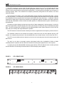
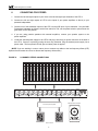
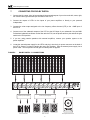
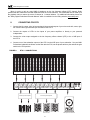
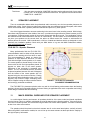
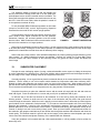
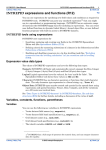
bass management
operation manual
LFE-4
Miller & Kreisel Sound, Inc.
9351 Deering Avenue
Chatsworth, CA 91311-5858 USA
(818) 701-7010 fax (818) 701-0369
www.mkprofessional.com
©2003 Miller & Kreisel Sound, Inc.
Bass Management Controller
TABLE OF CONTENTS
1.
2.
4.
5.
6.
7.
8.
9.
10.
11.
12.
13.
14.
15.
SAFETY PRECAUTIONS..........................................................................................................3
M&K’S DESIGN PHILOSOPHY...................................................................................................4
THE LOGIC OF BASS MANAGEMENT, OBSERVATIONS BY KEN KREISEL..........................4
INTRODUCTION.........................................................................................................................5
INPUT AND OUTPUT CONNECTOR WIRING...............................................................7
GENERAL CONNECTION GUIDELINES........................................................................7
GROUNDING......................................................................................................................7
CONNECTING FOR STEREO......................................................................................................8
CONNECTING FOR DOLBY DIGITAL.........................................................................................9
CONNECTING FOR DTS...........................................................................................................10
CALIBRATING YOUR M&K PROFESSIONAL SYSTEM...........................................................11
THE M&K PROFESSIONAL TEST DISC......................................................................11
SPEAKER PLACEMENT.....................................................................................................12
ITU-R BS.775.1 RECOMMENDATION...........................................................................12
GENERAL GUIDELINES FOR SPEAKER PLACEMENT..........................................................12
SUBWOOFER PLACEMENT.....................................................................................................13
SPEAKER CALIBRATION....................................................................................................14
SUBWOOFER CALIBRATION...................................................................................................14
SPECIFICATIONS.....................................................................................................................15
DIAGRAMS
FIGURE 1
FIGURE 2
FIGURE 3
FIGURE 4
FIGURE 5
FIGURE 6
FIGURE 7
FIGURE 8
FRONT PANEL.................................................................................................................6
REAR PANEL...................................................................................................................6
GROUNDING..................................................................................................................7
STEREO CONNECTIONS................................................................................................8
DOLBY DIGITAL 5.1 CONNECTIONS.............................................................................9
DTS 5.1 CONNECTIONS...............................................................................................10
ITU-R BS.775-1 SPEAKER PLACEMENT......................................................................12
SPEAKER CABINET ORIENTATION.............................................................................13
Please record the following information for your records:
Serial Number:
Date of Purchase:
Dealer Name:
Dealer Address:
City/State/Zip:
Country:
Invoice Number:
2
Bass Management Controller
The exclamation point within an
equilateral triangle is intended to
alert the user of the presence of
important operating and maintenance (servicing) instructions in
the literature accompanying the
appliance.
1.
CAUTION:
TO PREVENT THE RISK OF ELECTRIC SHOCK,
DO NOT REMOVE COVER (OR BACK). NO USERSERVICEABLE PARTS INSIDE. REFER SERVICING TO QUALIFIED SERVICE PERSONNEL.
The lightning flash with arrowhead,
within an equilateral triangle, is
intended to alert the user of the
presence of uninsulated “dangerous
voltage” within the product's enclosure that may be of sufficient magnitude to constitute a risk of electric
shock to persons.
SAFETY INSTRUCTIONS
1. READ INSTRUCTIONS - All safety and operating instructions should be read before this product is operated.
2. RETAIN INSTRUCTIONS - The safety and operating instructions should be retained for future reference.
3. HEED WARNINGS - All warnings on this product and in the operating instructions should be adhered to.
4. FOLLOW INSTRUCTIONS - All operating and use instructions should be followed.
5. ATTACHMENTS - Do not use attachments not recommended by the product manufacturer as they may cause hazards.
6. WATER AND MOISTURE - Do not use this product near water - for example, near a bathtub, washbowl, kitchen sink,
or laundry tub; in a wet basement; or near a swimming pool; and the like.
7. ACCESSORIES - Do not place this product on an unstable cart, stand, tripod, bracket, or table. The product may fall,
causing serious injury to a child or adult, and serious damage to the product. Use only with accessories recommended
by the manufacturer, or sold with the product. Any mounting of the product should follow the manufacturer's instructions
and should use a mounting accessory recommended by the manufacturer.
8. POWER SOURCE - This product should be operated only from the type of power source indicated on the marking label. If
you are unsure of the type of power supply to your home, consult your product dealer or local power company.
9. OVERLOADING - Do not overload wall outlets or extension cords as this can result in a risk of fire or electric shock.
10. LIQUID ENTRY - Never spill any liquid of any kind on the product.
11. SERVICING - Do not attempt to service this product yourself. Opening or removing covers, including any over bottom or
side speaker drivers, may expose you to dangerous voltage or other hazards. Refer all service to qualified service
personnel.
12. DAMAGE REQUIRING SERVICE - Unplug this product from the wall outlet and refer servicing to qualified personnel under
the following conditions:
•When the power-supply cord or plug is damaged.
•If liquid has been spilled, or objects have fallen into this product.
•If the product does not operate normally by following the operating instructions. Adjust only controls that are covered by the
operating instructions as an improper adjustment of other controls may result in damage and will often require extensive
work by a qualified technician to restore the product to its normal operation.
•If the product has been dropped or damaged in any way.
•When the product exhibits a distinct change in performance - this indicates a need for service.
13. REPLACEMENT PARTS - When replacement parts are required be sure the service technician has used replacement part
specified by the manufacturer or have the same characteristics as the original part. Unauthorized substitutions may result in
risk of fire, electric shock, or other hazard.
14. SAFETY CHECK - Upon completion of any service or repairs to this product, ask the service technician to perform safety
checks to determine that the product is in proper operating condition.
15. HEAT - This product should be situated away from heat sources such as radiators, heat registers, stoves, or other products
(including amplifiers) that produce heat.
3
Bass Management Controller
2.
M&K’S DESIGN PHILOSOPHY
Our philosophy is that exciting and lifelike sound and music reproduction takes place when your ears, in effect,
become the recording microphones. Our speakers are designed to allow you to hear exactly what the microphones
heard, placing you as close or as far away from the music or sound source as the recording engineer placed the
microphones.
Too many so-called "music" loudspeakers are designed with a philosophy that all recordings should sound as
if the music comes from a stage 10 or 20 rows distant, even if a recording is closely miked with performers as close
as a few inches from the microphones (as is often done on film soundtracks, especially for dialog).
This "homogenizing" effect may be pleasant for some music recordings, but it inaccurately reproduces both
close-miked recordings and those recordings that accurately capture the acoustic space of a recording site. This
is why many "music" speakers do so poorly when trying to reproduce both the intensity and intimacy of closely
miked sound effects and dialog on today's best soundtracks.
As an audiophile recording engineer and a high-end loudspeaker designer, my strong belief has always been
that a good loudspeaker should accurately and realistically reproduce whatever the microphone captured, whether
the source is a human voice, a musical instrument, an explosion, car crash, etc.; including the acoustical ambiance
of the environment in which the source was recorded.
Ken Kreisel
co-founder and CEO
M&K Sound Co.
3.
THE LOGIC BEHIND BASS MANAGEMENT
OBSERVATIONS by Ken Kreisel
Engineers mixing multi-channel audio (Stereo, Dolby Surround, 5.1 Dolby Digital, DTS, and other surroundsound formats) are faced with numerous challenges when trying to accurately monitor complex and dynamic
material, and determine how this material will sound in its intended playback space. These issues include
reproducing 5, 7, or more channels of full range audio, plus an optional Low Frequency Effects channel (LFE), all
of which have a bandwidth to 10Hz or below, with very high dynamic range, and achieving consistent bass
response from all the channels throughout the control room monitoring area.
Any studio designer will tell you that for a stereo mix environment it is crucial that the left and right monitor
speakers, when in their selected studio location, have near identical bass response when measured at the mixer's
position. No less is true in multichannel mixing. Proper low frequency equalization and mixing decisions are
difficult, if not impossible, unless all 5.1 or more channels have the same bass frequency response at the mixers
listening position.
Due to unavoidable room modes, five or more correctly placed full range speakers, (in even the most
perfectly designed studio) will produce dramatically different low frequency characteristics at the mix position. This
is especially true for the very crucial center channel speaker. Variations of 10 to 20dB may be measured at
frequencies below 80Hz.
When the bass from all the channels is redirected into a single, PROPERLY placed subwoofer, then each and
all of the multiple channels exhibits the identical bass response at the listening position, and gives surprisingly even
coverage in virtually every control room. Simply stated bass management is putting an electronic bass frequency
crossover (typically 80Hz) on all the channels, and redirecting the bass frequencies below 80Hz from each of the
channels to a common subwoofer.
4
Bass Management Controller
By combining a carefully designed low frequency acoustic rolloff of all the main speakers, including the
surrounds, and a matching 2nd order electronic filter in the M&K Bass Management Controller, M&K achieves all
the theoretical benefits of a 4th order Linkwitz-Riley filter. In addition, to further create a seamless bass managed
system, we use only non-ported sealed cabinet designs on all our speakers and subwoofers, eliminating ported
speaker phase anomalies which would prohibit smooth transitions at the bass managed crossover frequency.
Another good reason for using bass management in the control room is that even the least expensive Dolby
Digital consumer decoder, found in millions of homes, has bass management built in, allowing the bass from all
channels to be fed to a single subwoofer. Also, all Home THX systems utilize an 80Hz bass management system.
Monitoring with proper bass management in the professional control room insures proper playback translation into
the "home theater" environment and into larger spaces such as motion picture theaters.
It is important to understand that Bass Management is done as a function of the monitoring system and in no
way affects the actual mix. Full frequency musical content, is assigned or panned around the room via normal
console or software operations to the various desired subjective locations such as Left, Center, Right, Left
Surround, and so on. This full frequency musical data corresponding to each speaker location channel is stored
normally on tape, hard drive, etc.
Bass Management psychoacoustically works because the ear-brain mechanism cannot detect direction at low
frequencies, but takes its directional cues from the harmonics of the low frequency sound. In the monitoring
process, frequencies below 80Hz are redirected to the subwoofer. Frequencies above 80Hz are sent to the desired
speaker. During the hearing process, our hearing mechanism integrates the sound into the correct spatial
auditory image.
Bass management is equally suited to all formats from 2-channel stereo to 5.1 and beyond. Indeed, existing
control rooms that are doing stereo 2 channel mixes, especially with smaller nearfield monitors placed on the
console, can benefit immensely from the correct integration of Bass Management and a subwoofer; because the
engineer is now able to hear low frequency anomalies caused by room rumble, microphone stand thumping, breath
pops, and other artifacts that cause undesirable actions later in the broadcast, film chain, or DVD Mastering
process.
When mixes are intended for theatrical presentation, it is sometimes necessary to use an additional channel
for extra low frequency effects or enhancement. This channel is called the LFE or Low Frequency
Effects/Enhancements channel. In the control room monitoring environment, the LFE channel, if or when it is used
in the mix, is monitored by the same subwoofer used for the regular [L,C,R,LS,RS] channels. M&K Bass
Management Controllers have both a 0dB (with unity gain) and +10dB (with 10dB gain) inputs to accommodate
any mixing / monitoring situation, as per Dolby specifications.
The M&K Professional Division supplies, at no additional charge, a special CD test disc to assist in the
proper setup and calibration of our Bass Management Systems. This disk has pre-filtered and calibrated tracks of
noise which allow quick, accurate, and error-free setup of the monitoring environment to the Dolby standard of
85dB SPL, or any other relative reference level, by using an SPL meter.
4.
INTRODUCTION
The LFE-4 Bass Management Controller is a balanced, line-level studio bass management controller which is
intended for use with the M&K line of professional studio monitors. Although the LFE-4 was primarily designed for
monitoring 5.1 audio, its flexible architecture allows it to be used for monitoring mono, stereo, Dolby Surround,
Dolby Digital, DTS and other formats.
The LFE-4 combines several necessary functions in one 19” rack mount, 1RU package. Along with bass
management and LFE channel control, it also provides individual channel adjustment capability to properly
calibrate your entire monitor system.
5
Bass Management Controller
The LFE-4 consists of a series of five high-pass filters (one each for the L, C, R, LS, LR channels) that route
high frequency information (above 80Hz) to their appropriate channel’s amplifier and speaker monitor. Each
channel is also routed through a matching 80Hz low-pass filter. This low frequency information is then routed to a
summing amplifier, which in turn sends this low frequency information, along with the LFE channel, to two dual
subwoofer outputs.
This is done for two reasons. First, small loudspeakers cannot reproduce information below 80Hz. At least,
not with any authority. This information is therefore summed together and redirected from the individual channels
to a loudspeaker that can reproduce this low frequency information with clarity and power – a subwoofer. With the
introduction of digital audio, it has become necessary for loudspeaker systems to be able to accurately reproduce
audio that has a bandwidth of 20Hz to 20kHz with wide dynamics. A satellite/subwoofer system is the best way to
accomplish this.
Secondly, most home theater receivers have some form of bass management in their processors. In order for
work done in the studio to translate properly, the mixer must hear his mix exactly the way it will ultimately be played
back. The LFE-4 together with a properly set-up and calibrated M&K monitor system allows the mixer to hear his
work with more accuracy than might otherwise be possible.
The LFE channel is a discrete channel created by the mixer to supplement the low frequency content of the mix.
The subwoofer channel is the summed low frequency content from the five main channels plus the LFE
channel. It is created by the processor in the encoder/decoder of your chosen format, or in this case, the LFE-4.
The LFE-4 correctly balances these channels so the mixer can accurately hear how the format processor will
affect his mix.
The goal is to be able to accurately monitor multi-channel audio with a bandwidth of 20Hz to 20kHz
containing extreme dynamics and have that audio translate accurately when played back on other systems.
A properly set-up and calibrated M&K monitoring system with an LFE-4 will allow the mixer to make quick and
accurate decisions in a listening environment that he will find satisfying and enjoyable.
FIGURE 1:
LFE-4 FRONT PANEL
LFE-4
Subwoofer
FIGURE 2:
Left
Right
Center
Studio Bass Management Controller
Left Surround
Right Surround
LFE-4 REAR PANEL
SIGNAL
GND
RIGHT SUR
IN
RIGHT SUR
OUT
LEFT SUR
IN
LEFT SUR
OUT
RIGHT
IN
RIGHT
OUT
CENTER
IN
CENTER
OUT
6
LEFT
IN
LEFT
OUT
LFE IN
+0 dB
LFE IN
+10 dB
SUB OUT
1
SUB OUT
2
24 VAC
IN
CHASSIS
GND
Bass Management Controller
Input and Output Connector Wiring
The XLR connectors on the LFE-4 are wired as follows:
Pin 3:
Pin 2:
Pin 1:
Minus
Plus
Ground
General Connection Guidelines
To avoid loud transients that may damage your speakers and hurt your ears, turn off your power amplifiers
before connecting or disconnecting any cables or the power supply on the LFE-4.
Certain types of audio cables have high capacitance in the range of 0.75pf/ft. Long runs of high capacitance
cable can cause a decrease in high frequency performance of the LFE-4. Approximately 300 feet of 0.75pf/ft cable
will cause a drop of 3dB at 24kHz. In order to keep this effect to a minimum, use high-quality, low capacitance
cable or keep your cable runs from the LFE-4 to your amplifier to under a hundred and fifty feet.
5.
GROUNDING
The LFE-4 was designed so as not to add noise to an already clean system. To eliminate the possibility of the
extra safety ground introducing ground loop hum, the LFE-4 uses an external double-insulated UL approved power
transformer that does not require a safety ground. The LFE-4 is grounded to the audio signal ground of the mixer
and power amplifiers through the XLR cables. In order to minimize the grounding problems between the LFE-4
and equipment racks, the internal audio signal ground can be separated from the chassis ground. On the rear of
the unit are two binding posts. The black binding post is connected to the chassis. The red binding post is
connected to the audio signal ground. Normally, these binding posts are shorted together with a gold-plated
jumper. However in a situation where the chassis may be connected to a "dirty" ground, this jumper can be
removed, separating the audio and chassis ground. In addition, the binding post can be used to attach an
additional heavy gauge grounding wire.
FIGURE 3:
GROUNDING
Ground to clean
audio ground
if necessary
Remove jumper
SIGNAL
GND
24 VAC
IN
CHASSIS
GND
Ground to
rack
TECHNICAL TIP:
It is sometimes a common practice to only ground XLR cables at one end to prevent ground loops through the
cable. In order to work correctly, the LFE-4 must be grounded to either the mixing console or the power amps or
both. This is normally done through the XLR cables. If you are using XLR cables with the shield disconnected at
one end for both inputs and outputs, you must use the RED binding post to connect the LFE-4 to the audio
system ground.
7
Bass Management Controller
6.
CONNECTING FOR STEREO
1. Connect the left and right outputs of your mixer to the left and right input channels of the LFE-4.
2. Connect the left and right outputs of LFE-4 to the inputs of your power amplifiers or directly to your
powered loudspeakers.
3. Connect one of the subwoofer outputs of the LFE-4 to the XLR input of your subwoofer. Set your M&K
Professional subwoofer as follows: set the filter switch for THX, set the phase switch to plus and set the
gain switch to the THX position.
4. If you are using passive speakers with external amplifiers, connect your speaker system to the
power amplifiers.
5. Locate the external power supply for the LFE-4 and plug it into the 4 pin power connector on the back of
the LFE-4. Secure it in place by turning the outer ring clockwise. Plug the external power supply into a
power outlet. The front panel LED will glow red when power is applied.
(NOTE: If you are working in mono or stereo, do not connect any cables to the low frequency effects (LFE)
inputs as these formats do not use a discrete low frequency effects track.)
FIGURE 4:
2-CHANNEL STEREO CONNECTIONS
SIGNAL
GND
RIGHT SUR
IN
RIGHT SUR
OUT
LEFT SUR
IN
LEFT SUR
OUT
RIGHT
IN
RIGHT
OUT
CENTER
IN
CENTER
OUT
LEFT
IN
2-channel power amplifier
Main monitors
8
LEFT
OUT
LFE IN
+0 dB
LFE IN
+10 dB
SUB OUT
1
SUB OUT
2
M&K powered subwoofer
24 VAC
IN
CHASSIS
GND
Bass Management Controller
7.
CONNECTING FOR DOLBY DIGITAL
1. Connect the left, center, right, left surround and right surround outputs of your mixer to the left, center, right,
left surround and right surround input channels of the LFE-4.
2. Connect the outputs of LFE-4 to the inputs of your power amplifiers or directly to your powered
loudspeakers.
3. Connect the mixer output assigned to the low frequency effects channel (LFE) to the +10dB input of
the LFE-4.
4. Connect one of the subwoofer outputs of the LFE-4 to the XLR input of your subwoofer. Set your M&K
Professional subwoofer as follows: set the filter switch to THX, set the phase switch to plus and set the gain
switch to the THX position.
5. If you are using passive speakers with external amplifiers, connect your speaker system to the
power amplifiers.
6. Locate the external power supply for the LFE-4 and plug it into the 4 pin power connector on the back of
the LFE-4. Secure it in place by turning the outer ring clockwise. Plug the external power supply into a
power outlet. The front panel LED will glow red when power is applied.
FIGURE 5:
DOLBY DIGITAL 5.1 CONNECTIONS
SIGNAL
GND
RIGHT SUR
IN
RIGHT SUR
OUT
LEFT SUR
IN
LEFT SUR
OUT
2-channel power amplifier
Surround monitors
RIGHT
IN
RIGHT
OUT
CENTER
IN
CENTER
OUT
LEFT
IN
LEFT
OUT
LFE IN
+0 dB
LFE IN
+10 dB
SUB OUT
1
SUB OUT
2
3-channel power amplifier
Main monitors
9
M&K powered subwoofer
24 VAC
IN
CHASSIS
GND
Bass Management Controller
(Note: In order to gain an extra 10dB of headroom on the low frequency effects (LFE) channel, Dolby
specifies that this channel be recorded 10dB lower than the 5 main channels. This 10dB lower level is made up in
the playback chain to restore the correct 5 channel to .1 channel balance. For additional information please see
the "Dolby Digital Professional Encoder Manual" which is available from the Dolby website. (www.dolby.com)
8.
CONNECTING FOR DTS
1. Connect the left, center, right, left surround and right surround outputs of your mixer to the left, center, right,
left surround and right surround input channels of the LFE-4.
2. Connect the outputs of LFE-4 to the inputs of your power amplifiers or directly to your powered
loudspeakers.
3. Connect the mixer output assigned to the low frequency effects channel (LFE) to the +0 dB input of
the LFE-4.
4. Connect one of the subwoofer outputs of the LFE-4 to the XLR input of your subwoofer. Set your M&K
Professional subwoofer as follows: set the filter switch to THX, set the phase switch to plus and set the gain
switch to the THX position.
FIGURE 6:
DTS 5.1 CONNECTIONS
SIGNAL
GND
RIGHT SUR
IN
RIGHT SUR
OUT
LEFT SUR
IN
LEFT SUR
OUT
2-channel power amplifier
Surround monitors
RIGHT
IN
RIGHT
OUT
CENTER
IN
CENTER
OUT
LEFT
IN
LEFT
OUT
LFE IN
+0 dB
LFE IN
+10 dB
SUB OUT
1
SUB OUT
2
3-channel power amplifier
Main monitors
10
M&K powered subwoofer
24 VAC
IN
CHASSIS
GND
Bass Management Controller
5. If you are using passive speakers with external amplifiers, connect your speaker system to the
power amplifiers.
6. Locate the external power supply for the LFE-4 and plug it into the 4 pin power connector on the back of
the LFE-4. Secure it in place by turning the outer ring clockwise. Plug the external power supply into a
power outlet. The front panel LED will glow red when power is applied.
9.
CALIBRATING YOUR M&K PROFESSIONAL SYSTEM
1. For this set-up procedure, you will need the following:
a.)
b.)
c.)
d.)
e.)
An SPL meter. Radio Shack has an analog SPL meter that is very effective and not expensive.
The M&K Professional test CD.
A small, flat bladed screwdriver (or “tweeker”) to adjust the channel trim pots on the LFE-4.
A CD player, or DVD player that can play CD-R’s.
An M&K speaker system with the LFE-4 Bass Management Controller.
2. It may be helpful to have one person sit at the listening position and read the meter while another person
adjusts the trim pots on the LFE-4.
3. When the slot of the channel trim pots on the LFE-4 are pointing straight up and down, the gain of each
of the channels is approximately 0dB or unity. The trim pots have a plus or minus 12dB gain range.
Rotating the pot counter-clockwise will attenuate the channel a maximum of –12dB and rotating the pot
clockwise will boost the channel gain a maximum of +12dB. The maximum output of the LFE-4 is + 27dBu.
With a nominal signal level of + 4dB with 20dB of headroom, the maximum signal level from the source
(console, etc.) can be + 24dB. Therefore, at very high signal levels you can only add around + 3dB of gain
with the trim pots before the signal chain of the LFE-4 overloads. If you need more than 3dB of gain at
high signal levels, it is better to increase the output of power amplifiers and use the trim pots on the
LFE-4 to reduce the gain.
The M&K Professional test disc
A specially designed and produced test disc has been included with your LFE-4.
Ken Kreisel has designed this test disc expressly for use with M&K satelite/subwoofer loudspeaker systems.
The tones on this disc are all bandwidth-limited Pink noise. This is to avoid room anomalies and therefore provide
a more accurate calibration. By using this disc with a Radio Shack SPL meter and following the instructions in this
manual, you can achieve a remarkably accurate system calibration.
The goal here is not to find an absolute SPL level, but to balance the SPL level of all channels relative to each
other. For this application, the Radio Shack SPL meter will work very well.
If a more accurate calibration is desired, we recommend using a real time analyzer with calibrated microphones and appropriate room analyzing software.
Following are the tones found on the M&K test disc:
Track one:
Band limited Pink Noise from 500Hz to 3kHz recorded at –20dB FSD. Use this tone to
calibrate your main and surround (satellite) speakers.
Track two:
Band limited Pink noise from 40Hz to 80Hz recorded at -20dB FSD. Use this tone to
adjust your subwoofer level.
11
Bass Management Controller
Track three:
10.
1 kHz sine wave recorded at –20dB FSD. Use this to set the reference level of your source
(console, etc.) On an analog console this will be 0VU. On digital sources this will be either
–20dB FSD or –18dB FSD.
SPEAKER PLACEMENT
There is considerable debate within the professional audio community as to the best speaker placement for
multichannel mixing. Some mixers use placement solutions that are understood and well accepted, while others
remain unconvinced about a speaker placement standard and prefer to try other options.
One of the biggest obstacles to accurate monitoring in the control room is the recording console. With its large,
flat surface and its placement in the middle of the room, it provides the largest reflective surface between you and
your speakers. Reflected sound coming off the console arrives later than direct sound. The combination of direct
and reflected sound creates distortion in the form of comb-filtering. For this reason, we recommend that you do
not place your speakers on the console itself, but rather on stands around the console or wall-mounted on
brackets above the console. M&K manufactures a full line of stands and brackets which are designed to solve
practically any installation problem. Check with your M&K dealer or log onto the M&K Professional website,
www.mkprofessional.com for details.
ITU-R BS.775-1 Speaker Placement
Many professionals find the ITU-R BS.775-1
recommendation useful as either a final placement
solution or as a starting point from which to work.
This recommendation is based on placing the
speakers at equal distances around a 2.5 meter
circle with the height of each speaker at 1.2 meters.
The center speaker is placed directly in front of the
listener with the left and right speakers placed 30
degrees on either side of the center speaker.
Placement of the surrounds is somewhat more
flexible. The ITU recommends that the surrounds
be placed anywhere between 100 and 120 degrees
from the location of the center speaker with 110
degrees being the most common solution. Placing
the surrounds farther behind the mixer (120 to 135
degrees) may cause the single enveloping sound
field to collapse leaving the listener with two distinct
and seemingly unrelated soundfields.
FIGURE 7: ITU-R BS.775-1 SPEAKER
PLACEMENT RECOMMENDATION
The ITU-R BS.775-1 placement solution works very well in critical listening environments where the listening
position is known and is especially effective for those working in applications like music composition and mixing,
sound design, broadcast and DVD authoring.
11.
M&K’S GENERAL GUIDELINES FOR SPEAKER PLACEMENT
In a multi-channel listening environment, all speakers should be of the same model and placed equidistant
from the listener. This is to maintain coincidental arrival of all channels at the listening position. If the center channel must be a smaller speaker, we recommend using the MPS-1520 center channel speaker. It’s timbre is matched
to that of our other main monitors.
The speakers should be placed so that their tweeters are all on the same lateral plane, vertically oriented.
When using M&K’s multi-tweeter models, be sure to line up the center tweeters as these provide the majority of
the high frequency information.
12
Bass Management Controller
The speakers should be placed so that the tweeters are
directly in line with the listener’s ears, that is, on-axis. (M&K powered speakers have a red LED recessed into the front baffle. The
listener will know when his speakers are on-axis when he can see
this LED. If this LED is not visible, either the speaker is turned-off
or the speakers are aimed off-axis).
Do not place M&K MPS Professional speakers on their sides
(except for the MPS-1520), as their high frequency dispersion
characteristics are tuned for their normal upright position.
All five speakers in a surround sound system should be of the
same model or with Tripole surrounds for the rear speakers.
Sometimes, however, the surround speakers must be smaller
than the mains. M&K Professional offers several smaller models
that are timbre matched to our larger speakers.
FIGURE 8:
CABINET ORIENTATION
When placing loudspeakers around a video monitor, it is best to place all three main speakers either all above
or all below the screen. Placing the center channel speaker on a different horizontal plane from the left and right
speakers will create different arrival times and will adversely effect imaging.
When used near a video monitor, select shielded loudspeakers to prevent gaussing (magntic distortion) of the
video monitor. All M&K Professional monitors are shielded. However, be careful not to place M&K Tripole
surround monitors near video monitors as the side-firing drivers may gauss the video monitor and distort the
visual image.
12.
SUBWOOFER PLACEMENT
Perhaps the most challenging aspect of tuning a subwoofer/satellite monitor system is finding the best place
to put the subwoofer in the listening room. Each room exhibits unique characteristics and challenges because of
the wide range of size, shape, building materials and equipment in the room.
Generally speaking, it is not a good idea to place the subwoofer directly in the center between the left and right
speakers. There’s usually a null in this location which absorbs low frequencies rather than reinforcing them.
Instead, try placing the subwoofer near a wall or even in a corner of the control room. When properly set up, the
low end will still sound tight and phase-coherent with the satellites even though the subwoofer is placed off-center.
This is because the wavelengths of low frequencies are very long and are omni-directional.
Remember that when you place the subwoofer near a wall the sound will couple with the wall and create an
extra 3dB of gain. Place the subwoofer in a corner and you will pick up additional 3dB of gain.
An effective way to find the best location for the subwoofer is to start out by placing the subwoofer at the
listening position. Connect an audio source to the input of the subwoofer and play music with good low-end
content through the subwoofer. While the music is playing, move around the room in areas that you think might be
good locations for the subwoofer’s final placement. Try to locate an area that responds well to the music being
played by the subwoofer. Listen for even, well-defined, low frequency response. Once you have settled on a
possible placement, move the subwoofer to that location. Experiment with aiming the subwoofer directly at the
console, or aiming it at a wall or even aiming it along a wall. Once you have found a good placement solution for
the subwoofer, play program material that you are familiar with through the satellites and subwoofer and check the
sound quality. Two-channel material is good for this as the imagery of the phantom center depends upon equal
volume from both channels and phase coherency of the satellites with the subwoofer.
Using the guidelines in this manual and with a little experimentation, it will be possible to find a solution for
almost any room.
13
Bass Management Controller
13.
SPEAKER CALIBRATION
1. Your speakers should now be in their final positions.
2. Remove all EQ and signal processing from the monitor path.
3. Turn all volume controls in the signal chain to their “reference level” position. These volume controls
include the console main monitor pot, submaster faders and power amplifier volume pots. The “reference
level” position is your defined reference playback level, which is typically 85dB SPL for film, video and
music. For the purposes of this discussion, we will assume that 85dB SPL is your reference level. If you
use a different reference level, then substitute the level that you use whenever you see 85dB SPL.
4. Transfer one channel only (left or right) of the M&K Professional test CD onto your audio storage medium
(Pro Tools, open reel recorder, etc.). It is important that the tones be played back from your source through
the normal routing of your console or Pro Tools system so that the system calibration is conducted through
the same signal path that your audio goes through.
5. Select track three on the test CD and use the 1kHz tone to level-set your console for 0VU on an analog
console, or –18 FSD if working digitally. Do not move the faders once you have level-set your monitor path.
6. Select track one on the test CD and route it to the speaker that you want to calibrate (for example:
left front).
7. Set your SPL meter for C weighting (flat) and slow (average) response. Set the scale to 80dB. Hold the
meter at about a 45 degree angle to vertical and at arm’s length to avoid a false reading from sound
bouncing off your body and into the microphone. Point the meter at the center speaker at about ear height.
Play track one of the test CD through the selected speaker and read the SPL. Adjust the level to 85dB
using a small screw driver on the trim pot on the selected channel of the LFE-4.
8. Do the same for all front (or main) speakers and point the meter at each speaker in turn. The meter’s
microphone is directional.
9. Do the same for the surround speakers (Note: the film community prefers to use 82dB as the reference
level for surround speakers while DVD authors, broadcasters and music mixers prefer to set all their
speakers, including the surrounds, to the 85dB standard.)
(NOTE 1: If you are using a Martinsound MultiMax, connect the LFE-4 to the output of the MultiMax and
disengage the Cinema low-end reinforcement program on the MultiMax as this program is not a bass
management system.)
(NOTE 2: If your speakers are moved, it is recommended that the whole system be re-calibrated.)
14.
SUBWOOFER CALIBRATION
1. Set your SPL meter for C weighting and slow response. Set the scale to 80dB. Point the meter at the
center speaker at ear height with the meter at a slightly up-turned angle. Play track two of the test CD
through the selected speaker and read the SPL (Remember that the LFE-4 will re-route all frequencies
below 80 Hz to the subwoofer.) Adjust the subwoofer level using a small screw driver to 85dB on the
subwoofer trim pot on the LFE-4.
2. Next, route track two on the TEST CD to each of the 5 channels. Make sure that the subwoofer level is
exactly 85dB SPL for all channels. If they are not, you may have a frequency response problem in the
signal path that will have to be corrected before proper calibration can be achieved.
14
Bass Management Controller
15.
LFE-4 SPECIFICATIONS
All outputs have a +/- 12dB trim control for balancing the system .
LCR and Surround channels:
Input Impedance:
Output Impedance:
High pass filter:
Nominal input level:
Maximum recommended input level:
Output clipping level:
Gain Adjustment:
THD ( 1kHz @+4 dBu):
20K ohm balanced
200 ohms balanced
80Hz- 12 dB/octave
+4 dBu
+24 dBu
+27 dBu
+/- 12dB
0.002%
LFE Inputs:
Input impedance:
Nominal input level:
Maximum input level:
Gain Adjustment:
Gain +10dB input:
Lowpass filter:
THD ( 1kHz @+4 dBu):
20K ohm balanced
+4 dBu
+24 dBu
+/-12dB
+1 0dB
125Hz 24dB/octave
0.002%
Subwoofer Output:
Output impedance:
Nominal output level:
Filters for LCR and Surround:
Filter for LFE :
THD (20Hz @+4 dBu):
200 ohm balanced
+4 dBu for +4 dBu input
80Hz 24dB/octave
125Hz 24dB/octave
0.002%
15
7/08/2003
LFE-4 manual
PN # 70360
rev.1
pt/qrk