1
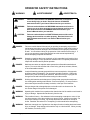
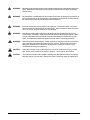
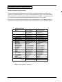
E
Operator's
Manual
Vision 21i
VisionV
READ THIS BOOK
This book has important information for the use and safe operation of this machine. Failure to read
this book prior to operating or attempting any service or maintenance procedure to your ALTO
machine could result in injury to you or to other personnel; damage to the machine or other property
could occur as well. You must have training in the operation of this machine before using it. If you
or your operator(s) cannot read English, have this manual explained fully before attempting to operate
this machine.
Si Ud. o sus operadores no pueden leer el Inglés, se hagan explicar este manual completamente antes
de tratar el manejo o servicio de esta máquina.
All directions given in this book are as seen from the operator’s position at the rear of the machine.
For new books write to: ALTO U.S. INC., 2100 Highway 265, Springdale, Arkansas 72764.
Form No. 78493B
2/00
CLARKE TECHNOLOGY
Printed in the USA
Table of Contents
Operator Safety Instructions ............................................................................................................ 3
Introduction & Machine Specifications ............................................................................................. 5
Procedures For Transporting ............................................................................................................ 6
Symbols Used On Vision 21i & Vision V .......................................................................................... 7
Machine Control Panel 21i & Vision V .............................................................................................. 8
Machine Control Panel 21i & Vision V .............................................................................................. 9
Machine Controls and Features ........................................................................................................ 10
How To Prepare The Machine For Operation .................................................................................... 11
How To Install The Batteries ............................................................................................... 11
Battery Maintenance .......................................................................................................... 12
How To Charge The Batteries ............................................................................................ 13
How To Install The Brushes Or Pad Drivers ....................................................................... 14
How To Remove The Brushes Or Pad Drivers .................................................................... 14
How To Operate The Machine ......................................................................................................... 15
How To Operate The Squeegee .......................................................................................... 15
How To Fill The Solution Tank ........................................................................................... 15
How To Clean A Floor ........................................................................................................ 17
How To Correct Problems In The Machine ...................................................................................... 18
Maintenance ................................................................................................................................... 20
Accessories .................................................................................................................................... 25
Drawings and Part Lists
Vision 21i - Vision V Rear Cover Assembly Drawing ....................................................................... 26
Parts List ........................................................................................................................... 27
Vision 21i - Vision V Traverse System Assembly Drawing .............................................................. 28
Parts List ........................................................................................................................... 29
Vision 21i - Vision V Squeegee & Squeegee Arm Assembly Drawing ............................................. 30
Parts List ........................................................................................................................... 31
Vision 21i - Vision V Brush Head Assembly Drawing ...................................................................... 32
Parts List ........................................................................................................................... 33
Vision 21i - Vision V Solution/Vacuum System Drawing ................................................................. 34
Parts List ........................................................................................................................... 35
Vision 21i - Vision V Brush Housing Assembly ............................................................................... 36
Parts List ........................................................................................................................... 37
Vision 21i - Vision V Alternate Brush Motor (44809A) Assembly Drawing and Parts List ................. 38
Vision 21i - Vision V Alternate Brush Motor (44809A) Drawing and Parts List ................................. 39
Vision 21i - Vision V Brush Motor (45037A) Drawing & Parts List ................................................... 40
Vision 21I - Vision V Traverse Motor (45038A) Drawing & Parts List ............................................... 41
Battery Charger Drawing & Parts List .............................................................................................. 42
Vision 21i - Vision V Vac Motor (44917A) ....................................................................................... 43
Vision 21i - Vision V Electrical Schematic ...................................................................................... 44
Vision 21i - Vision V Connection Diagram, Front of Machine ........................................................... 45
Vision 21i - Vision V Connection Diagram, Rear of Machine ............................................................ 46
Vision 21i - Vision V Connection Diagram, Inside Rear Cover .........................................................
Page -2-
Clarke Technology Operator's Manual -Vision 21i - Vision V
OPERATOR SAFETY INSTRUCTIONS
WARNING
AVERTISSEMENT
ADVERTENCIA
DANGER:
Failure to read and observe all DANGER statements could result in
severe bodily injury or death. Read and observe all DANGER
statements found in your Owner's Manual and on your machine.
WARNING:
Failure to read and observe all WARNING statements could result in
injury to you or to other personnel; property damage could occur as
well. Read and observe all WARNING statements found in your
Owner's Manual and on your machine.
CAUTION:
Failure to read and observe all CAUTION statements could result in
damage to the machine or to other property. Read and observe all
CAUTION statements found in our Owner's Manual and on your
machine.
DANGER:
Failure to read the Owner's Manual prior to operating or attempting any service or
maintenance procedure to your Clarke Technology machine could result in injury to
you or to other personnel; damage to the machine or to other property could occur
as well. You must have training in the operation of this machine before using it. If
you or your operator(s) cannot read English, have this manual explained fully
before attempting to operate this machine.
DANGER:
Operating a machine that is not completely or fully assembled could result in injury
or property damage. Do not operate this machine until it is completely assembled.
Inspect the machine carefully before operation.
DANGER:
Machines can cause an explosion when operated near flammable materials and
vapors. Do not use this machine with or near fuels, grain dust, solvents, thinners,
or other flammable materials.
DANGER:
Lead acid batteries generate gases which can cause an explosion. Keep sparks
and flames away from batteries. Do not smoke around the machine. Charge the
batteries only in an area with good ventilation. Make sure that you unplug the AC
charger from the wall outlet before diconnecting from the machine.
DANGER:
Working with batteries can be dangerous! Always wear eye protection and protective clothing when working near batteries. Remove all jewelry. Do not put tools or
other metal objects across the battery terminals, or the tops of the batteries.
DANGER:
Using a charger with a damaged power cord could result in an electrocution. Do
not use the charger if the power cord is damaged.
WARNING:
Operating this machine from anywhere other than the back of the machine could result in
injury or damage. Operate this machine only from the rear.
WARNING:
This machine is heavy. Get assistance before attempting to transport or move it. Use
two able persons to move the machine on a ramp or incline. Always move slowly. Do
not turn the machine on a ramp. Do not stop and leave the machine on a ramp or
incline. Read the "Procedures For Transporting" in this manual before transporting.
WARNING:
Machines can topple over if guided over the edges of stairs or loading docks and cause
injury or damage. Stop and leave this machine only on a level surface. When you stop
the machine, turn the key "OFF".
Clarke Technology Operator's Manual - Vision 21i - Vision V
3
WARNING:
Maintenance and repairs performed by unauthorized personnel could result in damage or
injury. Maintenance and repairs must be performed by authorized Clarke Technology
personnel only
WARNING:
Any alterations or modifications of this machine could result in damage to the machine or
injury to the operator or other bystanders. Alterations or modifications not authorized by
the manufacturer voids any and all warranties and liabilities.
WARNING:
Electrical components of this machine can "short-out" if exposed to water or moisture.
Keep the electrical components of the machine dry. Wipe the machine down after each
use. For storage, keep the machine in a dry building.
WARNING:
Operating a machine without observing all labels and instructional information could
result in injury or damage. Read all machine labels before attempting to operate. Make
sure all of the labels and instructional information are attached or fastened to the machine. Get replacement labels and plates from your Clarke Technology distributor.
WARNING:
Wet floor surfaces can be slippery. Water solutions or cleaning materials used with this
type of machine can leave wet areas on the floor surface. These areas can cause a
dangerous condition for the operator or other persons. Always put "Caution" signs
around/near the area you are cleaning.
CAUTION:
Use of this machine to move other objects or to climb on could result in injury or damage. Do not use this machine as a step or furniture. Do not ride on this machine.
CAUTION:
Your machine warranty will be voided if anything other than genuine Clarke Technology
parts are used on your machine. Always use Clarke Technology parts for replacement.
Page -4-
Clarke Technology Operator's Manual -Vision 21i - Vision V
Introduction & Machine Specifications
Introduction & Machine Specifications
Clarke Technology’s newly designed Vision 21i & Vision V automatic scrubbers are efficient and
superior floor cleaning machines. The Vision 21i uses two brushes or pads to scrub a path 21 inches
wide. The Vision V uses two brushes or pads to scrub a path 26 inches wide. A squeegee wipes the
floor while the vacuum motor removes the dirty solution from the floor - all in one pass.
The Vision 21i or Vision V automatic scrubbers come complete with four - 6 volt batteries or two - 12
volt batteries, one battery charger, either two brushes or two pad drivers, and one operator’s manual.
SPECIFICATIONS:
Model
Motor, Vac
Power Supply
Solution Tank
Recovery Tank
Parabolic Squeegee
Motors, Brush (2)
Motor Traction
Drive Train
Brushes (2)
Brush Speed
Brush Pressure
Speed, Forward
Speed, Reverse
Drive Wheel
Charger
Length
Width
Height
Cleaning Rate
Cleaning Swath
Grade Cleaning
Weight
Shipping Weight
Battery Weight(4-250 AH)
(2-195 AH)
Vision V- 00590A
¾ HP three
stage tangential
discharge - 21 Amp
24 volt*
195AH, 250AH
20 gallon (76 liter)
20 gallon (76 liter)
37 inches (94 cm)
.5 hp PM (.37 kw) 23 amp
.5 hp PM (.37kw) 23 amp
Direct Drive, Roller Chain
13 inch (33cm)
320 rpm
100 lbs.
3 speeds to 220ft/min.
2 speeds to 170ft/min.
12"x6" (30x15cm)
24V, 25A, 115V/60hz
58 inches (147cm)
27 inches (70cm)
42 inches (106cm)
29,000 sq ft/hr
(2,694 sq. m/hr)
26 inch (66cm)
5° Incline
492 lbs.
602 lbs.
264 lbs.
224 lbs.
Vision 21i-00610A
¾HP three
stage tagential
discharge - 21 Amp
24 volt *
195AH, 250AH
20 gallon (76 liter)
20 gallon (76 liter)
27 inches (69 cm)
.5 hpPM (.37 kw) 23 amp
.5 hp PM (.37kw) 23 amp
Direct Drive, RollerChain
11 inch (28cm)
320 rpm
100 lbs
3 speeds to 220ft/min.
2 speeds to 170ft/min.
12"x6" (30x15cm)
24V, 25A, 115V/60hz
57 inches (145cm)
23 inches (58cm)
42 inches (106cm)
23,000 sq ft/hr
(2,136 sq. m/hr)
21 inch (53cm)
5° Incline
462 lbs.
572 lbs.
264 lbs.
224 lbs.
NOTE: * 24V (4-6v batteries or 2-12v batteries)
Clarke Technology Operator's Manual - Vision 21i - Vision V
5
PROCEDURES FOR TRANSPORTING
How To Put The Machine In A Van Or Truck
WARNING:
The machine is heavy. Make sure you use two able persons to assit
the machine in climbing the ramp.
1. Make sure the loading ramp is at least eight (8) feet long, and strong enough to support the machine.
2. Make sure the ramp is clean and dry.
3. Put the ramp in position.
4. Remove squeegee assembly, brush housings, & brushes or pad drivers before loading.
5. Turn key switch "ON".
6. Align the machine on a level surface ten (10) feet in front of the ramp.
7. Put the traverse speed switch in the "HI" position.
8. Push the control handles toward the machine all the way.
9. Push the machine to the top of the ramp.
10. Engage the parking brake.
11. Turn the key switch "OFF".
12. Fasten the machine to the vehicle.
How To Remove The Machine From A Van Or Truck
1. Make sure there are no obstructions in the area.
2. Make sure the unloading ramp is at least eight (8) feet long and strong enough to support the machine.
3. Make sure the ramp is clean and dry.
4. Put the ramp in position.
5. Unfasten the machine.
WARNING:
The machine is heavy. Make sure you use two able persons to assist in
moving the machine down the ramp.
6. Turn the key switch "ON".
7. Release the parking brake.
8. Put the traverse speed switch in the "HI" position.
9. Carefully and slowly, pull the machine to the top of the ramp.
10. As the machine begins to travel down the ramp, push the control handles toward the machine to
maintain a slow downward speed.
11. Replace squeegee assembly, brush housings, & brushes or pad drivers after the machine is unloaded
and ready to use.
Page -6-
Clarke Technology Operator's Manual -Vision 21i - Vision V
SYMBOLS USED ON VISION 21i & Vision V
Warning
Power
On/Off Key Switch
Traverse Speed
Solution Control
Brush Up/Down
Clarke Technology Operator's Manual - Vision 21i - Vision V
7
MACHINE CONTROL PANEL (Vision 21i & Vision V)
Key Switch (See Figure #1, Item "A")
The key switch turns "ON" the power to the control panel. "0" is "OFF" and "1" is "on".
Traverse Speed Switch (See Figure #1, Item "B")
The speed switch has three positions: High, Medium, and Low speeds.
Brush Position Switch (See Figure #1, Item "C")
The brush switch has two positions: "Up" positions the brushes up; "Down" positions the brushes on the floor. The
brush motors start when the brushes are down.
Solution Control Knob (See Figure #1, Item "D")
The solution control knob regulates the flow of cleaning solution to the floor. To increase the flow turn the knob
clockwise. To decrease the flow, turn the knob counter-clockwise.
Control Handles (See Figure #1, Item "E")
The control handles are located at the rear of the machine. They control the direction of the machine. Push forward to
go forward. (See Figure #2, page 7). Pull back to move in reverse. (See Figure #3, page 7).
Circuit Breakers (See Figure #1, Item "F"-"J")
The circuit breaker reset buttons are located on the rear cover, below the control handle. The breakers are located as
follows:
Item F & G - Brush Motors (35A)
Item H - Traverse Motor (30A)
Item I - Vac Motor (30A)
Item J - Actuator Motor, Brush Head (5A)
If a circuit breaker trips, determine which motor is not operating and turn the key switch "OFF". Wait five minutes and
push the reset button back in. Turn the key switch "ON", and try again. An authorized service person should be
contacted if the breaker trips again.
Page -8-
Clarke Technology Operator's Manual -Vision 21i - Vision V
MACHINE CONTROL PANEL (Vision 21i & Vision V)
B
C
D
A
E
F G
H
I J
Figure #1
Figure #2
Clarke Technology Operator's Manual - Vision 21i - Vision V
Figure #3
9
MACHINE CONTROLS & FEATURES
Squeegee Lift Handle. See Figure #4a & #4b.
The squeegee lift handle is located below the control
handles on the right side. It is used to raise or lower
the squeegee. The vac motor is turned on when the
handle is lowered.
Figure #4a
Float Shut Off. See Figure #5.
The shut-off switch for the vac motor is located in the
recovery tank. It automatically turns off the vac
motor when the recovery tank is full.
Parking Brake. See Figure #6a & #6b.
Figure #4b.
The parking brake prevents movement of the machine. It is located at the rear lower left side of the
machine. To engage the brake, push the pedal down
(Figure #6a). To release the brake, lift pedal up
(Figure #6b).
CAUTION: Do not activate the brake
while the machine is moving.
Figure #5.
Figure #6a.
Page -10-
Figure #6b.
Clarke Technology Operator's Manual -Vision 21i - Vision V
HOW TO PREPARE THE MACHINE FOR OPERATION
How To Install The Batteries
The Vision 21i and Vision V machines use four 6-volt
or two 12-volt batteries. The batteries are located in
the battery compartment under the recovery tank.
To Install the batteries, follow this procedure:
1. Set the parking brake.
Figure #7a
2. Make sure both tanks are empty.
All 6 Volt
Poly Case Batteries
3. Disconnect the hoses from the recovery tank
(upper tank) & unplug the vac motor.
Remove the recovery tank.
4. Remove the two screws that attach the
solution tank (lower tank) to the back of the
frame, leaving the two angle brackets
attached to the tank.
5. Disconnect the two hoses under the right
side and remove the solution tank.
Figure #7b
6. Place the batteries in the tray as shown in
figure #7a, #7b, or #7c.
330 AH, 6 Volt
Black Rubber Case Battery
WARNING:
Lifting batteries without
help could result in an
injury. Get help to lift the
batteries. The batteries are
heavy.
WARNING:
Working with batteries can
be dangerous. Always
wear eye protection and
protective clothing when
working near battiers.
NO SMOKING!
7. Connect the battery cables between
batteries and install long battery cable
assembly as indicated. See figure #7.
Figure #7c
12 Volt 195 AH
8. Join the connector from the battery pack to
the connector on the control panel. See
figure #8.
9. Install the tank, reconnecting hoses and
replace the two screws attaching the
solution tank to the rear of the frame.
NOTE: Charge the batteries before using the
machine.
Figure #8
Clarke Technology Operator's Manual - Vision 21i - Vision V
11
HOW TO PREPARE THE MACHINE FOR OPERATION
Battery Maintenance
The electrical power to operate the machine comes from
the storage batteries. Storage batteries need preventive
maintenance.
WARNING:Working with batteries can be dangerous. Always wear eye protection
and protective clothing when working near batteries.
NO SMOKING!
To maintain the batteries in good condition, follow these
instructions:
1. Keep the electrolyte at the correct level. The correct
level is between 1/4" below the bottom of the tube in
each cell and above the tops of the plates. Check the
level of the electrolyte each time you charge the
batteries. See figure #9.
NOTE: Check the level of electrolyte prior to charging the
batteries. Be sure the plates in each cell are covered with
electrolyte . Do not top off the cells prior to charging the
battery. Electrolyte expands during charging. As a result,
the electrolyte could overflow from the cells. Always top
off the cells with distilled water after charging.
Correct Fill Level
CAUTION:
Irreversible damage will occur to
the batteries if the electrolyte level
does not cover the plates. Keep the
electrolyte at the correct level.
CAUTION:
Machine damage and discharge
across the tops of the batteries can
occur if the batteries are filled above
the bottom of the tube in each cell.
Do not fill the batteries up to the
bottom of the tube in each cell.
Wipe any acid from the machine or
the tops of the batteries. Never add
acid to a battery after installation.
CAUTION:
Tap water may contain contaminants that will damage batteries.
Batteries must be re-filled with distilled water only.
2.
Keep the tops of the batteries clean and dry.
Keep the terminals and connectors clean. To clean
the top of the batteries, use a damp cloth with a
weak solution of ammonia or bicarbonate of soda
solution. To clean the teminals and connectors,
use a terminal and connector cleaning tool. Do
not allow ammonia or bicarbonate of soda to get
into batteries.
3.
Keep the batteries charged.
Page -12-
Figure #9
Clarke Technology Operator's Manual -Vision 21i - Vision V
HOW TO PREPARE THE MACHINE FOR OPERATION
How To Charge The Batteries
WARNING:
Charging the batteries in an area
without adequate ventilation
could result in an explosion. To
prevent an explosion, charge the
batteries only in an area with
good ventilation.
WARNING:
Lead acid batteries generate
gases which could explode. Keep
sparks and flames away from batteries. NO SMOKING!
WARNING:
Failure to disconnect the AC plug
from the wall receptacle before
connecting or disconnecting the
DC connector on the charger
could result in an explosion. Always disconnect the AC plug
from the wall receptacle before
connecting or disconnecting the
DC connector on the charger.
Figure # 10
To charge the batteries, follow this procedure:
1. Put the charger on a flat surface. Make sure the
vents on the sides are at least two inches away from
walls and other objects. Make sure there are no
objects near the vents on the bottom of the charger.
2. Set the parking brake by putting it into the down
position. See figure #10. Make sure the key switch
is “OFF” position.
3. Disconnect the battery pack connector from the
control housing connector. See figure # 11.
Figure #11
4. Connect the DC connector on the charger to the
battery pack connector. See figure #12.
5. Connect the charger to a properly grounded single
phase (3-wire) wall receptacle having the voltage,
frequency, and ampere capacity specified on the
nameplate of the charger.
For more instruction on the use of the charger, read the
instruction book supplied with the charger.
Figure #12
Clarke Technology Operator's Manual - Vision 21i - Vision V
13
HOW TO PREPARE THE MACHINE FOR OPERATION
How To Install The Brushes Or Pad Drivers
To install the brushes or pad drivers on the machine,
follow this procedure:
1. Engage the parking brake.
2. Turn the key switch "ON".
3. Put the brush switch in the "UP" position.
4. Turn the key switch "OFF".
5. Go to the front of the machine.
6. Pull out the brush housing pin and remove the
right and left brush housings.
Figure # 13
7. Put a brush or pad driver under the brush motor plate.
See figure #13.
8. Align the lugs on the motor gimbal with the slots in the
brush gimbal.
9. Pull the brush up until the gimbal locks.
10. Repeat steps 7, 8, and 9 to install the second brush
or pad driver.
How To Remove The Brushes Or Pad Drivers
To remove the brushes or pad drivers from the
machine,follow this procedure:
1. Engage the parking brake.
2. Turn the key switch "ON".
3. Put the brush switch in the "UP" position.
4. Turn the key switch "OFF".
5. Go to the front of the machine.
6. Push down on two sides of the brush or pad driver until
the gimbals release.
Page -14-
Clarke Technology Operator's Manual -Vision 21i - Vision V
HOW TO OPERATE THE MACHINE
How To Operate the Squeegee
The squeegee wipes the floor while the vacuum motor
removes the dirty solution from the floor. Use your right
hand to lower or raise the squeegee handle. To operate the
squeegee, follow this procedure:
1. To lower the squeegee and start the vac motor move
the squeegee lever to the right and down. See figure
#14a.
2. To raise the squeegee, lift the squeegee lever up.
See figure #14b.
Note: The center position lets the vac motor continue to
run with the squeegee off the floor to avoid drips.
Figure #14a
How to Fill The Solution Tank
CAUTION: Make sure water or solution
does not enter the opening for
the vacuum motor. See figure
#15.
The solution tank lid is at the front. To fill the solution tank
follow this procedure:
1. Remove the solution tank lid.
2. Fill the solution tank with water.
Figure#14b
3. Add a cleaning chemical to the water. for the
correct amount, follow the directions shown on the
container.
4. Replace the solution tank lid.
Figure #15
Clarke Technology Operator's Manual - Vision 21i - Vision V
15
HOW TO OPERATE THE MACHINE (cont.)
WARNING:
Water solutions or cleaning materials used with this type of machine
can leave wet areas on the floor
surface. These areas can cause a
dangerous condition for the operator or other persons. Always put
CAUTION signs near the area you
are cleaning.
WARNING:
Machines can ignite flammable materials and vapors. Do not use with
or near flammables such as gasoline, grain dust, solvents and
thinners. Only use a cleaning concentrate recommended by the
chemical manufacturer.
Figure # 16
NOTE: Put the machine in the "LO" traverse speed. Use
the machine in an area that has no furniture and objects
until you can do the following:
1. Move the machine in a straight direction, forward and
backward.
2. Stop the machine safely.
3. Move the machine in a straight direction after you turn
the machine.
To move the machine, follow this procedure:
1. Release the parking brake.
2. Turn the key switch “ON” position.
Figure #17
3. Put the brush switch in the "UP" position.
4. Raise the squeegee.
5. To go forward, push the control handles toward the
machine. See figure #16.
6. To stop the machine, put the handles in the center
position.
7. To go backward, pull the handles away from the
machine. See figure #17.
8. To turn the machine, push the rear of the machine to
the side.
9. When you stop the machine, turn the key switch
"OFF".
Page -16-
Clarke Technology Operator's Manual -Vision 21i - Vision V
HOW TO OPERATE THE MACHINE (cont.)
HOW TO CLEAN A FLOOR
WARNING: Water solutions or cleaning materials used with this type of machine
can leave wet areas on the floor
surfaces. These areas can cause a
dangerous condition for the operator or other persons. Always put
CAUTION signs near the area you
are cleaning.
3
To clean a floor, follow this procedure:
1. Set the parking brake.
2. Put the water and a cleaning chemical in the clean
solution tank.
3. Release the parking brake.
4
4. Turn the key switch "ON".
5. Lower the squeegee.
6. Put the brush switch in the "DOWN" position.
2
NOTE: Keep the machine moving when the brushes are
rotating on the floor. (I models only)
7. Turn the solution knob to the right to activate the flow
of solution. Adjust the flow of clean solution to the
flow desired.
8. Move the machine across the floor in the forward
direction. See figure #18 (1).
9. When the machine is one machine length from the end
of the area to be cleaned (figure #18 (2)), rotate the
solution knob to the left.
1
10. Make a 1800 turn. See figure #18 (3).
NOTE: When you make more passes across the floor, let
the brushes clean approximately 2 inches of the
area already cleaned by the brushes. See figure
#18 (4).
NOTE: During most cleaning procedures, apply and
remove the solution in one operation.
HOW TO CLEAN A VERY DIRTY FLOOR
To clean a very dirty floor, follow this procedure:
1. Apply solution to the floor.
Figure #18
2. Do not lower the squeegee.
3. Do not activate the vacuum motor.
4. Lower the brushes and scrub the floor.
5. Leave the solution on the floor long enough for the
solution to begin cleaning the floor.
6. Scrub the floor again with additional solution, picking
up all the solution with the squeegee
Clarke Technology Operator's Manual - Vision 21i - Vision V
17
HOW TO CORRECT PROBLEMS IN THE MACHINE
PROBLEM
There is no solution flow.
The solution flow does not stop.
The machine does not remove all the
water from the floor.
CAUSE
ACTION
The solution valve is closed.
Open the solution valve.
There is an obstruction in the solution hose
or filter.
Remove the obstruction from the hose and the
filter.
The solution valve or linkage is damaged.
Repair or replace the valve and the linkage.
The solution tank is empty.
Fill the solution tank.
The solution valve is open.
Close the solution valve.
The solution valve or linkage is damaged.
Repair or replace the valve and the linkage.
The solution valve is dirty
Clean the solution valve.
There is a damaged seat and washer in the
solution valve.
Replace the seat and washer.
The valve stem is dirty
Clean and lubricate valve stem.
The squeegee is up
Lower the squeegee.
The squeegee tilt is not correct.
(See Figure 27)
The vacuum tank is full.
Drain the tank.
The screen filter is dirty.
Clean the screen filter.
There is an obstruction or damage in the
squeegee, squeegee hose or standpipe.
Remove the obstruction or repair the damage.
The vacuum motor is not running.
Check for tripped breaker. Have an authorized service person make repairs.
The squeegee hose is disconnected.
Connect the hose.
The squeegee blade is damaged, worn, or
incorrectly installed.
Turn or replace the squeegee blade.
Correctly install the squeegee blade.
The squeegee pressure is not correctly
adjusted.
Adjust the pressure of the squeegee.
The gaskets on the cover of the recovery
tank are damaged.
Replace the gaskets.
The battery terminals are dirty or damaged.
Clean the terminals and connectors. Replace
the damaged cables. Charge the batteries.
The electrolyte level is too low.
Add distilled water to each cell and charge the
batteries.
The batteries are not fully charged.
Charge the batteries for a full 16 hour charge.
The charger is damaged.
Have an authorized service person repair the
charger.
The battery is defective.
Check voltage of each cell while discharging.
The batteries are disconnected.
Connect the batteries.
The batteries do not give the normal
running time.
Page -18-
Clarke Technology Operator's Manual -Vision 21i - Vision V
PROBLEM
The cleaning is not even.
CAUSE
ACTION
The scrub brushes or pads are worn.
Replace the scrub brushes or pads.
There is damage to the brush assembly,
casters or the solution valve.
Have an authorized service person make
the needed repairs.
The brush motors are not running
Check for tripped breaker, reset. Check
for loose connections.
The solution level is low.
Fill the solution tank.
NOTE: If the problem continues consult
an authorized service person.
The machine does not run.
The machine loses power.
Reset the circuit breaker.
Check wire connection to traverse motor.
Check the battery connections.
NOTE: If the problem continues consult
an authorized service person.
NOTES
Clarke Technology Operator's Manual - Vision 21i - Vision V
19
MAINTENANCE
WARNING: Maintenance and repairs must be
done by authorized personnel only.
WARNING: Always empty the solution tank and
recovery tank before doing any
maintenance.
WARNING: Keep all fasteners tight.
These Maintenance Procedures Must Be Done Every
Day
Keep the machine clean, it will need fewer repairs and
have longer life.
Figure #19
Do These Procedures When You Begin Your Work
Period
NOTE: Always engage the parking brake before
servicing the machine.
1. Disconnect the plug on the charger from the
connector on the back of the machine. See
figure #19
2. Join the connector from the batteries (1) to the
control panel cable connection. See figure #19.
3. Make sure the recovery tank lid is on correctly.
See figure #20, Item A.
Figure #20
4. Make sure the Screen filter over the vacuum motor
is clean and in position. See figure #21, Item B.
5. Make sure the valves on the drain hoses are clean.
Tightly close the valves.
6. Make sure brush housings and skirts are in
position on the brush head.
7. Make sure the brushes are in position and
installed correctly
8. Check the installation of the squeegee and
squeegee hose.
Figure #21
Page -20-
Clarke Technology Operator's Manual -Vision 21i - Vision V
MAINTENANCE
Do These Procedures When You End Your Work
NOTE: Always engage the parking brake before servicing the machine.
1. Drain the solution tank (Figure #22a) and the recovery
tank (Figure #22b). To drain the tanks , follow this
procedure:
a. Turn the key switch “OFF”.
b. Remove the drain hose from the back of the
machine.
Figure #22a
c. Put the end of the hose over a drain or bucket.
d. Turn the valve handle to the left. Pull the handle
out to open the drain. (Figure #22c)
NOTE: Have the opening in the side of the valve away
from you when you open the valve.
e. To open the valve completely, turn the handle
to the right. Pull the handle out of valve. (Figure
#22d)
2. Flush the tanks. To flush the tanks, put clean water in
the tank through the opening on top of the tank.
3. If a tank or drain hose has an obstruction, use a high
pressure water hose to flush the tank or hose. Put the
water hose into the drain hose.
Figure #22b
4. Leave the tanks and the drain valves open to dry in the
air.
5. Check the squeegee blade. Use a cloth to clean the
squeegee blade. If the squeegee blade is damaged or
worn, turn or replace the blade.
6. Check and clean the solution lid gasket. Use a mild
cleaning solution and rinse the parts in clean water.
Check the batteries and add distilled water as needed. The
correct level is within 1/4 inch of the bottom of the tube in
each cell.
CAUTION: Tap water may contain contaminants that will damage batteries.
Batteries must be re-filled with
distilled water only.
Figure #22c
WARNING: Lead acid batteries generate
gases which can cause an explosion. NO SMOKING. Always wear
eye protection and protective
clothing when working near
batteries.
Use a clean cloth and wipe the surface of the machine.
Charge the batteries. See the instruction in the section of
this book called “How To Charge The Batteries”.
Clarke Technology Operator's Manual - Vision 21i - Vision V
Figure #22d
21
MAINTENANCE
These Maintenance Procedures Must Be Done Every
Week:
WARNING:
Maintenance and repairs must be
done by authorized personnel only.
Always empty the solution tank and
the recovery tank before doing any
maintenance. Keep all fasteners
tight.
WARNING: Always wear eye protection and protective clothing when working near
batteries. Do not put tools or other
metal objects across the battery terminals or the tops of the batteries.
CAUTION:
To prevent damage to the machine,
and discharge across the tops of the
batteries, do not fill the batteries
above the bottom of the tube in each
cell. Wipe any acid from the machine
or the tops of the batteries. Do not add
acid to battery after installation.
Figure #23
NOTE: Always engage the parking brake before servicing the machine.
WARNING: Always wear eye protection and protective clothing when working near batteries. NO SMOKING!
1. To inspect batteries, tip up recovery tank and pull out
the stop pin to hold the tank up. See Figure #23
2. Disconnect the batteries. Use a cloth and a solution
of ammonia or bicarbonate of soda to wipe the top of
the batteries. Clean the battery terminals. Reconnect
the batteries.
3. Check the hoses for leaks, obstructions and other
damages.
4. Check and clean the filter screen in the solution hose.
To clean the screen, follow this procedure:
a. Turn the connector to the left.
b. Remove and clean the filter screen.
Figure #24
c. Install the filter screen in the hose. Turn the
connector to the right to connect he hose.
5. Use a grease gun to lubricate the drive wheel and the
casters. See figure #24.
6. Apply a thin lubricant to the drive chain.
Page -22-
Clarke Technology Operator's Manual -Vision 21i - Vision V
MAINTENANCE
7. Check the squeegee and the scrub brushes or the pad
drivers for damage.
8. Check the squeegee and the vacuum hose for damage,
leaks and obstructions.
Maintenance For The Squeegee
To remove the squeegee, follow this procedure:
1. Remove the squeegee assembly by loosening the two
knobs that attach the squeegee to the machine. Pull
the squeegee assembly off. See figure #25.
Figure #25
2. Inspect the squeegee blade.
3. If the blade is worn, turn the blade so that a new edge
is in the wiping position.
4. Reinstall squeegee assembly on the machine.
How To Adjust The Squeegee
The following adjustments are set at the factory, however
they may require slight adjustment.
Adjusting Squeegee Pressure:
To adjust the pressure, refer to Figure #26. Proper
adjustment will produce a uniform flare along the rear
blade when the machine is moved forward. To increase
pressure, tighten the nuts on each side of the swing arm.
To decrease the pressure, loosen the nuts on each side.
Figure #26
Adjusting Squeegee Tilt:
The tilt of the squeegee causes the rear blade to raise up
in the center or on the ends, depending on which
direction the tilt is changed. For tilt adjustment, refer to
figure # 27. Loosen left and right screw "X". In order to
bring the rear blade down in the center, tip "Y" down. To
bring both ends down, tip "Y" up. Make very small
adjustments and try it until a uniform flare is achieved.
Changing the tilt may also require readjusting the squeegee pressure.
X
Y
Figure #27
Clarke Technology Operator's Manual - Vision 21i - Vision V
23
MAINTENANCE
Adjusting Squeegee Blades:
When properly installed the front blade should be approximately .06 above the rear blade. See figure #28.
Adjusting Squeegee Support Wheels:
The support wheels should be set at .12 above the floor
with the rear blade touching the floor. See figure #28.
REAR BLADE
.06
.12
Figure #28
WARNING: Maintenance and repairs must be
done by authorized personnel
only .
WARNING: Electrical repairs must be done by
authorized personnel only.
Consult your Clarke Technology Authorized Service
Person to do the service procedures.
Use only genuine Clarke Technology parts.
How to Clean the Solution Line
Figure #29
If the solution line becomes clogged, pull the filter
assembly out from the lower rear of the frame (Figure
#29) and remove the filter screen (Figure # 30) and clean
or replace it. Push filter assembly back inside frame.
Figure #30
Page -24-
Clarke Technology Operator's Manual -Vision 21i - Vision V
CLARKE TECHNOLOGY Vision 21i /Vision V
Accessories - 11/95
Accessories:
Description
Power Wand System Kit
ESP Recycle System Kit
Soft Caster (Wheel only)
Soft Traverse Wheel
Low Voltage Shut-off (24v)
Clarke Technology Care Kit
Frame Bumper
Roller Kit (one side per Kit)
Part No.
14634A
14633A
52127A
59952A
14097A
14607A
821203
14693A
Nitrile Squeegee Blades:
Length
28.12"
32.50"
Machine
21i
Vision V
Part No.
30938A
30949A
Ribbed Squeegee Blades:
Length
29.88"
25.88
Machine
Vision V
21i
Part No.
30948A
30942A
Brush Assemblies:
Size
11"
11"
11"
11"
13"
13"
13"
13"
Description
Poly
Grit- Heavy
Grit-Medium11444A
Soft-Nylon
Poly
Grit-Heavy
Grit-Medium11439A
Soft Nylon
Part No.
11442A
11443A
11441A
11438A
11440A
11437A
Pad Drivers:
Size
11"
13"
Part No.
17530A
17531A
Clarke Technology Operator's Manual - Vision 21i - Vision V
25
Page -26-
78
34 35
42
40
41 80 33 37
32
63
64
66
31 79
38
36
81
65
83
43
44
23
12
19
6
17
13
45
4 21
59
21
11
55
14 20
79
28
47
21
22
84
Clarke Technology Operator's Manual -Vision 21i - Vision V
47
7
82
27
23
16
8
15
30
75
4
3
54
46
1
50
4
63
23
89
2
3
67
87 88
48
57
71
776190 51
8560
18
55
65
49
72
62
56
70
85
48
85
53
23
ClLARKE TECHNOLOGY Vision 21i / Vision V
Rear Cover Assembly Drawing 7/99
10
84
39
24 25
2
23
84
40
26
23
12
x
x
x
x
x
x
x
x
x
x
x
x
x
x
x
x
x
x
x
x
x
x
x
x
x
x
x
x
x
x
x
x
x
x
x
x
x
x
x
x
x
x
x
x
x
x
x
x
x
x
x
x
x
x
x
x
x
x
x
x
x
x
x
x
x
x
x
x
x
x
x
x
x
x
x
x
x
x
x
x
x
x
x
Clarke Technology Operator's Manual - Vision 21i - Vision V
Ref #
43
44
45
46
47
48
49
50
51
53
54
55
56
57
59
60
61
62
63
64
65
66
67
70
71
72
74
75
77
78
79
80
81
82
83
84
85
86
87
88
89
90
Part No.
831105
836707
920280
73714A
63342A
61653A
856702
902731
41448A
41423A
85518A
64490A
47388A
85389A
87029A
80028A
438360
65619A
920056
60676A
962980
41146A
61260A
608210
962285
Pg. 28
980651
930093
41431A
46317A
87202A
980205
42404A
55413A
51867A
170915
87026A
85700A
962546
980675
68643A
41444A
Description
Qty
Tank stop Brushing
2
Pin
2
Nut, 5/8-18
2
Warning Plate
1
Frame Weldment
1
Squeegee Lift Cable
1
Hairpin
2
Nyliner Bushing
2
Circuit Breaker, 30A (Vac) 1
Circuit Breaker, 5A (Hd. Act.)
5
Screw, ¼-20 x 3/4 PN
Handle
1
Switch Asm., Vac
1
Screw, 3/8-16 x 5/8 PN
1
Washer, Flat 3/4
1
Bolt
1
Spring
1
Squeegee Lift Lever
1
Nut, 6-32 ESNA
4
Power, Conn. Bracket
1
Screw, 6-32 x 1 PN
4
Console Cable Assembly 1
Squeegee Lift Bracket
1
Spacer
1
Screw, ¼-20 x 1 Flat
1
Pin Bracket ref. #25
1
Washer, Flat 5/16
1
Rivet
2
Circuit Breaker 35A (Br. Mtr.)
Relay, 3 sec. (HSD)
1
Washer, Lock
1
Washer
4
Diode Asm.
1
Key
1
Clamp, Cable
1
16
Screw, ¼-20 x 3/4 Hex
Washer, Flat ¼
8
Screw ¼-20 x 1 Hex
2
Screw, #10-24 X ½
2
Washer
2
Plate, Wear
1
Circuit Breaker 30A (Trav.) 1
Vision V
Description
Qty
Main Harness
1
Handle Pin
2
Screw,¼-20 x 1¼ PN
2
Washer, Lock 1/4
2
Control Handle
1
Control Handle Grip
2
Screw, 8-32 x ¼ Set
2
Key Switch, W/Key
1
Knob
1
Switch (Head Up/Down) 1
Switch (3 Speed Trav.)
1
Screw, 10-24 x ¾ PN
6
Gasket
2
Console Panel
1
Screw, 3/8-16 x 3 CR
2
Screw, ¼-20 x ½ PN
1
Stationary Handle
2
Washer, Starlock 3/8
1
Wiring Label
1
Cover Hinge
1
Screw, ¼-20 x 5/8 PN
8
Wiring Label
1
Nut, ¼-20 ESNA
20
Control Switch Collar
1
Centering Bracket
1
Spring
2
Stud
2
Insulator
2
Solution Control
1
Rear Cover
1
Screw, 5/16-18 x ½ Set
4
Cover Support, LH
1
Washer, Lock 5/16
4
Nut, 10-24 ESNA
2
Relay- .12 Sec. (F/N/R) 1
Nut, 3/8-16 Jam
2
Screw, 5/16-18 x 3/4 HX
4
Toggle Switch (Traverse) 1
Solenoid, Brush Motor
1
Solenoid, Vac, Speed Ctrl 3
Cover Support, RH
1
Solenoid, For./Rev.
2
Vision 21i
Part No.
49720A
66533A
85390A
980657
24308A
34608A
962262
47380A
55502A
47381A
47383A
962966
34264A
69339B
80011A
85395A
64462A
980666
77208A
64508A
85391A
77211B
81104A
61651A
60662A
53038A
83302A
854849
61652A
30024A
962304
69507A
980652
920296
46318A
81301A
85813A
10052A
41810A
878514
69506A
41811A
Vision V
Ref #
1
2
3
4
5
6
7
8
9
10
11
12
13
14
15
16
17
18
19
20
21
22
23
24
25
26
27
28
29
30
31
32
33
34
35
36
37
38
39
40
41
42
Vision 21i
CLARKE TECHNOLOGY Vision 21i / Vision V
Rear Cover Assembly Parts List 7/99
x
x
x
x
x
x
x
x
x
1
x
x
x
x
x
x
x
x
x
x
x
x
x
x
x
x
x
x
1
x
x
x
x
x
x
x
x
x
x
x
x
x
x
x
x
x
x
x
x
x
x
x x
x
x
x
x
x
x
x
x
x
x
x
x
x
x
x
x
x
x
x x
x
x
x
x
x
x
x
x
x
x
x
x
x
27
14
33
16
35
34
30 16
40
22
42
39
41
21
1
23
38
24
37
36
3
2
43
4
26
31
29
9
7
8
6
5
19 30
27
28
2
20
7
24
5
10
4
18
11
25
12
25
32
7
16
17
15
19
13
CLARKE TECHNOLOGY Vision 21i - Vision V
Traverse System Assembly Drawing 2/00
Page -28-
Clarke Technology Operator's Manual -Vision 21i - Vision V
Ref #
1
2
3
4
5
6
7
8
9
10
11
12
13
14
15
16
17
18K
19
20
21
22
23
24
25K
26
27
28
29
30
31
32K
33
34
35
36
37K
38
39
40
41
42K
NIK
Part No.
63342A
85727A
848302
81104A
87026A
438360
920110
838214
60412A
848508
67147A
925004
85814A
16703A
67877A
85811A
60663A
60246A
980651
85816A
915102
45038A
51828A
81105A
170892
170915
899769
980638
962593
980652
980205
85395A
52202A
898550
895158
838506
980475
69009A
60154A
883351
59944R
30063A
77266B
Description
Qty
Frame
1
Screw, 3/8-16 x 1 Hex
12
Brake Spring
1
Nut, ¼-20 Hex ESNA
4
Washer, Flat ¼
5
Spring
1
Nut, 5/16-18, ESNA
3
Brake Arm Spacer
1
Brake Arm
1
Brake Rod Swivel
1
Brake Rod
1
Cotter Pin
2
Screw, 5/16-18 x 1.25 Hx 1
Brake Lever
1
Brake Pedal Spacer
1
Screw, 5/16-18 x 3/4 Hex
5
Brake Pedal Bracket
1
Guard
1
Washer, Flat 5/16
3
Screw, 5/16-18 x 1.5 Hx
1
Key
1
Traverse Motor
1
Strap
1
Nut, 3/8-16 ESNA
12
Washer, Lock ¼
7
Screw, ¼-20 x 3/4
4
Caster Assembly
2
Washer, Lock 3/8
8
Screw, ¼-20 x 3/8 set
2
Washer, Lock 5/16
5
Washer
1
Screw, ¼-20 x ½
3
Chain
1
Drive Sprocket
1
Master Link
1
Driven Sprocket
1
Spacer Washer
3
Axle Strap
2
Shaft
1
Grease Fitting
1
Wheel Assembly
1
Sheild, Wheel Guard
1
Label, Parking Brake
1
Vision V
Vision 21i
CLARKE TECHNOLOGY Vision 21i - Vision V
Traverse System Assembly Parts List 2/00
x
x
x
x
x
x
x
x
x
x
x
x
x
x
x
x
x
x
x
x
x
x
x
x
x
x
x
x
x
x
x
x
x
x
x
x
x
x
x
x
x
x
x
x
x
x
x
x
x
x
x
x
x
x
x
x
x
x
x
x
x
x
x
x
x
x
x
x
x
x
x
x
x
x
x
x
x
x
x
x
x
x
x
x
x
x
NOTE: Kindicates a change has taken place
since last publication of this manual
Clarke Technology Operator's Manual - Vision 21i - Vision V
29
CLARKE TECHNOLOGY Vision 21i - Vision V
Squeegee & Squeegee Arm Assembly Drawing 1/97
34
11
ref.
45
35
33
34
42
21
37
23
22
32
24
21
18
20
31
30
39
29
19
43
11
38
27
25
28
12
26 17
44
41
14
16
10
15
46
9
11
26
13
7
8
26
36
5
6
40
2
3
4
1
Page -30-
Clarke Technology Operator's Manual -Vision 21i - Vision V
Ref #
1
2
3
4
5
6
7
8
9
10
11
12
13
14
15
16
17
18
19
20
21
22
23
24
25
26
27
28
29
30
31
32
33
34
35
36
37
38
39
40
41
42
43
44
45
46
Part No.
80011A
62712A
62430A
62424A
62421A
86004A
30946A
30931A
38719A
38713A
30947A
30930A
81301A
69613A
69059A
980687
59950A
962522
25201A
34260B
419702
61242A
170915
87026A
920256
81104A
60659A
68013A
60417A
61249A
81105A
962269
82505A
63009A
80015A
920056
962920
60420A
920110
56493A
18810A
18807A
836711
85727A
85704A
37016A
67899A
85811A
66531A
836711
60416A
81207A
Description
Qty
Screw, 3/8-16 x 3 CR
2
Duct
1
Clamp Weld
1
Clamp Weld
1
End Clamp
2
Screw, ¼-20 x 1.50 Hx
2
Outer Blade
1
Outer Blade
1
Spacer
2
Spacer
2
Inner Blade
1
Inner Blade
1
Nut, 3/8-16 JAM
6
Squeegee Weld.
1
Sq. Weld.
1
11
Washer 3/8 ID
Guide Wheel
2
Screw,3/8-16 x 1.50 Hex 2
Knob
2
Squeegee Gasket
1
Wheel
2
Tube Bracket
1
Screw, ¼-20 x 3/4 Hex
4
Washer, Flat ¼
5
Nut, 5/16-18 Hex
2
Nut, ¼-20 Hex ESNA
Squeegee Spring Brkt.
2
Squeegee Adj. Stud
2
Rear Arm
1
Pin Bracket
1
Nut, 3/8-16 ESNA
5
Screw, ¼-20 x 2.50 Hex 1
Squeegee Actuator Pin
1
Squeegee Lift Bar
1
Shoulder Bolt
1
Nut, 6-32 ESNA
4
Screw, ¼-20 x 3.4 Soc. 1
Front Arm
1
Nut, 5/16-18 ESNA
5
Squeegee Press. Spring 2
Squeege Asm.
1
Squeegee Asm.
1
Hairpin
3
Screw, 3/8-16 x 1 Hwx
1
Screw, 3/8-16 x 2¼
2
Pad
1
Washer, Flat 3/8 S.S.
1
Screw 5/16 - 18 x .75
2
Swing Arm Pin
1
Hair Pin
1
Arm, Pivot
1
Nut, 3/8-16 SS
2
Clarke Technology Operator's Manual - Vision 21i - Vision V
Vision 21i
Vision V
CLARKE TECHNOLOGY Vision 21i - Vision V
Squeegee & Squeegee Arm Assembly Parts List 1/97
x x
x x
x
x
x x
x x
x
x
x
x
x
x
x x
x
x
x x
x x
x x
x x
x x
x x
x x
x x
x x
x x
x x
x x
x x
x x
x x
x x
x x
x x
x x
x x
x x
x x
x x
x x
x x
x
x
x x
x x
x x
x x
x x
x x
x x
x x
x x
x x
31
CLARKE TECHNOLOGY Vision 21i - Vision V
Brush Head Assemby Parts List 9/98
47
59
46
46
34
54
53
45
41
48
22
51 66
52
42
36
43
3
60
37
64
9
1
39
11
36
3
38
35
9
36
6
3
66
28
71
30
68
21
62
Squeegee Arm
Stop Asm.
57
65
50
27
32
14
33
1 5
69
44
65
2
58
29
31
7
26
5
67
28
13
8
10
17
25
21
40
20
19
18
70
11
15 12
49
61
12
16
55
56
Page -32-
Clarke Technology Operator's Manual -Vision 21i - Vision V
13
14
15
16
17
18
19
20
21
22
23
25
26
Part No.
962980
47374A
920056
47405A
85519A
69434A
81104A
46508A
82501A
68661A
68670A
782002
34705A
34704A
722030
980638
170915
962714
82508A
833802
962495
Pg 23
34400B
836711
838502
915102
45037A
27
28
29
30
31
32
33
34
35
36
41601A
920365
63058A
962344
67705B
41602A
Pg. 33
38708A
67703A
82404A
11
12
Description
Screw, 6-32 x 1 PN
Lever Switch (Scrub Lmt.)
Nut, 6-32 ESNA
Switch, Brush (Head Up)
Screw, ¼-20 x 3/8 PN
Switch Bracket
Nut, ¼-20 ESNA
Resistor (Traverse Res.)
Pin
Brush Plate
Brush Plate
Clamp
Brush Hose L.H.& R.H.
Brush Hose L.H.& R.H.
Hose Clamp
Washer, Lock 3/8
Screw, ¼-20 x 3/4
Screw, 5/16-18 x 3/4 Soc
Pin
Gimbal
Screw, ¼-20 x 1 Pn
Brushes & Pads
Gimbal
Hairpin
Splitter, Water
Key
Motor, Brush
(ref. to pages 36 & 37)
Connector
Nut, ½-13 ESNA
Linkage Bar
Screw, ½-13 x 1¼ HX
Sleeve Bearing
Connector Housing
Solution Hose ref. #4
Nylon Washer
Head Pressure Sleeve
Spirol Pin, 3/16
Qty
4
1
6
1
4
1
2
1
2
1
1
2
2
2
1
8
8
2
1
2
6
2
2
3
1
1
2
2
8
4
2
8
2
1
2
1
3
x
x
x
x
x
x
x
x
x
x
x
x
x
x
x
x
x
x
x
x
x x
x
x
x x
x x
x x
x x
x x
x x
x x
x x
x x
x x
x x
x x
x
x
x
x
x
x
x
x
x
x
x
x
x
x
x
x
x
x
x
x
x
x
Ref #
37
38
39
40
41
42
43
44
45
46
47
48
49
50
51
52
53
54
55
56
57
58
59
60
61
62
63
64
65
66
67
68
69
70
71
Part No.
66530A
69100B
49720A
61658A
50204A
53400A
Description
Qty
Head Pressure Pin
1
Head Pressure Tube
1
Harness, Wiring
1
Gimbal Collar
2
Actuator
1
Head Pressure Spring
(ref. to pages 36 and 37) 1
69006A Spring Seat
1
63342A Main Frame
1
39007B Battery Tray
1
871334 Battery, 12 Volt, 195 AH 2
881317 Battery, 6 Volt, 250 AH
4
842406 Series Cable-9"
1
41206A Series Cable-16"
2
41211A Battery Cable
1
838301 Brush Holder Spring
2
77091A Label, Warning-Moving
3
77210A Label, Wiring
1
77209A Label, Battery Connect. 1
77092A Label, Warning-Battery
2
77093A Label, Warning-Falling
2
56941A Center Lok Asm.(Pad Driver only) 2
962737 Screw #10-16x7/8 (pad driver only) 6
80011A Screw 3/8-16 x 3 CR
2
81301A Nut, 3/8 -16 JAM
4
67887A Spacer, 12V Bat.
2
925006 Cotter Pin
1
962989 Screw, ¼-20 x 1½
2
962850 Screw, ½-13 x 1½ Hx
4
59856A Washer, Rubber
2
60509A Activator
1
81105A Nut, 3/8-16 ESNA
4
85727A Screw 3/8-16 x 1
4
980673* Washer
8
85735A Screw, Special Hd
2
81216A Nut, Spacer
2
170892 Washer, Lock ¼
8
70065A Label 26v
1
70066A Label, 21i
1
Vision 21i
Vision V
Ref #
1
2
3
4
5
6
7
8
9
10
Vision 21i
Vision V
CLARKE TECHNOLOGY Vision 21i - Vision V
Brush Head Assemby Parts List 9/98
x
x
x
x
x
x
x
x
x
x
x
x
x
x
x
x
x
x
x
x
x
x
x
x
x
x
x
x
x
x
x
x
x
x
x
x
x
x
x
x
x
x
x
x
x
x
x
x
x
x
x
x
x
x
x
x
x
x
x
x
x
x
x
x
x
x
x
x
x
x
x
x
x
x
-
*NOTE: #67 used with screws #62 only as needed to square
up linkage bars #29.
Clarke Technology Operator's Manual - Vision 21i - Vision V
33
CLARKE TECHNOLOGY Vision 21i - Vision V
Solution/Vacuum System Drawing 9/98
8
24
36
34 33
40
47
41
2
32
35
8
37
38
48
51 52
17
39
56
2
53
50
54
32
8
17
31
25
27
24
17
30
2
28
24
43
26
29
42
23
20
55 34
8
22
27
21
2
20
19
16
13
18
5
14 15
12
16
6
5
3
7
9
8
6
5
2
4
Page -34-
Clarke Technology Operator's Manual -Vision 21i - Vision V
2
3
4
5
6
7
8
9
10
11
12
13
14
15
16
17
18
19
20
21
22
23
24
25
26
27
28
Part No. Description
920296
820823
35199A
722030
822802
61652A
962798
849401
678215
832102
81104A
830214
838517
50335A
30412A
872010
85702A
35102A
832002
839401
833407
833901
52206A
962987
962943
30405A
85391A
Nut, 10-24 ESNA
Bracket
Solution Hose
Hose Clamp
Elbow
Solution Control
Screw, 10-24 x ½ Pan
Solution Valve
Spacer
Cable Clip
Nut, ¼-20 ESNA
Connector
Filter Screen
Hose Adapter
Hose
Hose Clamp
Screw, ¼-20 x 13/4
Drain Hose, Recovery
Clamp
Drain Valve
Drain Gasket
Drain Valve Handle
Chain
Screw, 10-24 x 3/8 PN
Screw, 8-18 x 1/2 PN
Drain Hose, Solution
Screw, ¼-20 x 5/8 PN
Qty
6
1
1
6
2
1
6
1
1
1
1
1
1
1
2
5
1
1
2
2
2
2
4
2
2
1
4
x
x
x
x
x
x
x
x
x
x
x
x
x
x
x
x
x
x
x
x
x
x
x
x
x
x
x
x
x
x
x
x
x
x
x
x
x
x
x
x
x
x
x
x
x
x
x
x
x
x
x
x
x
x
Clarke Technology Operator's Manual - Vision 21i - Vision V
Ref #
29
30
31
32
33
34
35
36
37
38
39
Vision 21i
Vision V
Ref #
Vision 21i
Vision V
CLARKE TECHNOLOGY Vision 21i - Vision V
Solution/Vacuum System Parts List 9/98
40
41
42
Part No.
60659A
30409B
30123A
837304
85728A
87026A
58533A
59319A
643418
44917A
41809A
43401A
43402A
832322
34256A
38984C
Description
Qty
Bracket
1 x x
Squeegee Hose
1 x x
Squeegee Adapter
1 x x
O-Ring
2 x x
Screw, ¼-20 x 4.00 Hex
3 x x
Washer, Flat ¼
5 x x
Vac Motor Spacer
3 x x
Stand, Tube
1 x x
Gasket
1 x x
Vac Motor
1 x x
Contact
4 x x
Housing Black - Vac
2 x x
Housing Blue - Float
2 x x
Lid
2 x x
Lid Gasket
2 x x
Solution Tank
1 x x
43
47
48
50
51
52
53
54
69443A
58012A
920797
14092A
56459A
87612A
170686
38985D
Bracket, Solution Tank LH
1
x x
Vacuum Strainer
Nut
Float Switch
Strain Relief
Seal
Locknut
Recovery Tank
1
1
1
1
1
1
1
x
x
x
x
x
x
x
55
56
170915
30410A
Screw, ¼-20 x 3/4 hex
Hose, Vac Motor
1
1
x x
x x
35
x
x
x
x
x
x
x
CLARKE TECHNOLOGY Vision 21i - Vision V
Brush Housing Assembly Drawing 7/96
3
4
5
14
1
2
7
8
6
9
10
Page -36-
12
11
Clarke Technology Operator's Manual -Vision 21i - Vision V
Ref #
1
2
3
4
5
6
7
8
9
10
11
12
13
14
Part No.
64729A
64727A
64728A
64726A
81105A
980687
419702
85704A
69089A
69079A
38235A
38234A
50449A
38236A
38233A
69090A
69078A
81104A
81104A
85737A
85737A
81301A
Description
Brush Housing, L.H.
Brush Housing, L.H.
Brush Housing, R.H.
Brush Housing, R.H.
Nut, 3/8-16 ESNA
Washer
Guide, Wheel
Scr., 3/8-16 x 2¼
Strap, R.H.
Strap, R.H.
Skirt, R.H.
Skirt, R.H.
Pin
Skirt, L.H.
Skirt, L.H.
Strap, L.H.
Strap, L.H.
Nut, 1/4-20 ESNA
Nut, 1/4-20 ESNA
Scr., 1/4-20 x 5/8 Hex
Scr., 1/4-20 x 5/8 Hex
Nut, 3/8-16 Jam
Clarke Technology Operator's Manual - Vision 21i - Vision V
Qty
1
1
1
1
1
1
1
1
1
1
1
1
1
1
1
1
1
9
11
9
11
1
Vision 21i
Vision V
CLARKE TECHNOLOGY Vision 21i - Vision V
Brush Housing Assembly Parts List 7/96
x
x
x
x
x
x
x
x
x
x
x
x
x
x
x
x
x x
x
x
x
x
x
x
x
x
x x
37
CLARKE TECHNOLOGY Vision 21i - Vision V
Alternate Brush Motor Assembly #44809A 5/95
NOTICE:
If your Vision V or Vision 21i has brush motor #44809A, shown
below, use the parts on this page. Refer to pages 30 and 31 in this
manual for other parts.
Ref.
1
2
3
4
Page -38-
Part No.
980638
962244
44809A
53412A
Description
Washer, Lock 3/8
Screw, 3/8-16 x 3/4
Motor, Brush
Head Pressure Spring
Qty.
8
8
2
1
Clarke Technology Operator's Manual -Vision 21i - Vision V
CLARKE TECHNOLOGY Vision 21i - Vision V
Alternate Brush Motor #44809A 5/95
Flam Location
Item
1
2
3
4
5
Part No.
56478A
50142A
902654
902550
51840A
6
7
8
9
10
11
12
13
14
15
16
17
50520A
56480A
962546
50517A
448396
40826A
55657A
55656A
59805A
50515A
44809A
54238A
Description
Stator Frame Assembly (w/Magnets & Clips)
Armature Assembly (w. B.E. & F.E. Bearings)
Bearings B.E.
Bearing F.E.
Commutator Bracket Assembly
(w/Brush BRD Assembly Leads)
Commutator Bracket
Strain Relief
Brush Board Screw
Brush Board Assembly (w/ Springs & Brushes)
Brush Spring
Brush Assembly
Lead Assembly
Lead Assembly
Helical Washer
Thru Bolt
Shaft Key
B.E. Bracket Assembly (Gear Box)
Clarke Technology Operator's Manual - Vision 21i - Vision V
Qty
1
1
1
1
1
1
2
2
1
4
4
1
1
1
2
1
1
39
CLARKE TECHNOLOGY Vision 21i - Vision V
Brush Motor #45037A 3/95
Ref #
1
2
3
4
5
6
7
8
9
10
11
12
13
Page -40-
Part No.
832315
980076
902547
50156A
902550
897655
830846
962955
50577A
833102
55133A
448396
40807A
Description
Qty
Com. Bracket Cover
1
Washer - Helical
1
Bearing
1
Armature Assembly
1
Bearing
1
Seal - Oil
1
Bracket
1
Screw ¼-20 x 5¾ Hex
2
Bracket Assembly
1
Field Asm. w/Mag Clips 1
Brush Holding Asm.
1
Spring -Brush
4
Brush Assembly
4
Clarke Technology Operator's Manual -Vision 21i - Vision V
CLARKE TECHNOLOGY Vision 21i - Vision V
Traverse Motor #45038A 8/94
Ref #
1
2
3
4
5
6
7
8
9
10
11
Part No.
52776A
980076
902547
50156A
902550
897655
830845
962955
50577A
833102
912206
12
13
14
15
912207
55133A
448396
40807A
Description
Cover, Bracket, Com.
Washer - Helical
Bearing
Armature Assembly
Bearing
Seal - Oil
Bracket
Screw ¼-20 x 5¾ Hex
Bracket Assembly
Field Asm. w/Mag Clips
Housing - Male Terminal
Connector
Terminal - Male
Brush Holding Assembly
Spring -Brush
Brush Assembly
Clarke Technology Operator's Manual - Vision 21i - Vision V
Qty
1
1
1
1
1
1
1
2
1
1
1
1
1
4
4
41
CLARKE TECHNOLOGY Vision 21i - Vision V
Battery Charger
Drawing & Parts List 8/94
WARNING: All electrical repairs must be performed by qualified personnel only.
Charger #40512A: 24 volt, 25 amp D.C., 115 volt, A.C., 60 Hz
Charger #40513A: 24 volt, 25 amp D.C., 230 volt, A.C., 50 Hz
Ref #
1
2
3
4
5
6
7
8
9
10
11
12
13
Page -42-
Description
Charger Case
Transformer
Electronic Controller Kit
Capacitor, 660 V.A.C.
Heat Sink Assembly
Ammeter
Fuse Holder
Strain Relief, A.C. Cord
Strain Relief, D.C. Cord
D.C. Cord Assembly
A.C. Cord Assembly
Housing
D.C. Plug Lock Key
Charger Model Number
40512A
40513A
Part #
Part #
41129A
41128A
48413A
48409A
47500A
48200A
912132
912132
912212
912212
40200A
40200A
912382
912382
837525
837525
747553
747553
51986A
51986A
51974A
908947
911470
911470
795020
795020
Clarke Technology Operator's Manual -Vision 21i - Vision V
Clarke Technology Vision 21i - Vision V
Vacuum Motor Model
Drawing 8/94
Form # 44917A
Ref #
1
2
* 3
4
5
6
7
* 8
9
* 10
11
* 12
13
Part No. Description
Qty
51913A Clip (optional)
2
54809A Housing Vent
1
Fan
1
85303A Screw - 8x32 - 3/8 P.N. 4
40817A Brush, Mechanism
2
51914A Clamp
2
50618A Bracket,Commutator E. 1
Bearing
1
672714 Disc
1
Bearing
1
59803A Washer, Neoprene
1
Bracket, Fan End
1
58500A Spacer
1
Clarke Technology Operator's Manual - Vision 21i - Vision V
Ref #
14
15
* 16
* 17
18
* 19
* 20
* 21
* 22
* 23
Part No. Description
53914A Fan, Rotating
658201 Spacer
Fan, Stationary
Shell, Fan
638313 Spring, Load
Fan, Air Seal
Fan, Stationary
Fan, Rotating
Washer
Nut
Qty
2
2
1
1
1
1
1
1
1
1
*NOTE: #'s 3, 8, 10, 12, 16, 17, 19, 20, 21, 22, & 23
are not available at this time.
43
CLARKE TECHNOLOGY Vision 21i - Vision V
Electrical Schematic 7/99
Page -44-
Clarke Technology Operator's Manual -Vision 21i - Vision V
CLARKE TECHNOLOGY Vision 21i and Vision V
Connection Diagram 1/97
Front of Machine (Tank Removed)
Clarke Technology Operator's Manual - Vision 21i - Vision V
45
CLARKE TECHNOLOGY Vision 21i and Vision V
Connection Diagram 1/97
Rear of Machine (Rear cover open)
Page -46-
Clarke Technology Operator's Manual -Vision 21i - Vision V
CLARKE TECHNOLOGY Vision 21i and Vision V
Connection Diagram 1/97
Inside Rear Cover
Clarke Technology Operator's Manual - Vision 21i - Vision V
47
NOTES
Page -48-
Clarke Technology Operator's Manual -Vision 21i - Vision V
ALTO® PRODUCT SUPPORT BRANCHES
U. S. A. Locations
HEAD OFFICE
European Locations
PRODUCTION FACILITIES
ALTO U.S. Inc., St. Louis, Missouri
390 S. Woods Mill Rd., Suite 300
Chesterfield, Missouri 63017-3433
PRODUCTION FACILITIES
ALTO U.S. Inc., Springdale, Arkansas
2100 Highway 265
Springdale, Arkansas 72764
(501) 750-1000
Customer Service - 1-800-253-0367
Technical Service - 1-800-356-7274
ALTO U.S. Inc., Bowling Green, Ohio 43402
1100 Haskins
ALTO U.S. Inc., Clearwater, Florida 33765
1500 N. Belcher Road
ALTO Danmark A/S, Aalborg
Blytaekkervej 2
DK-9000 Aalborg
+45 72 18 21 00
ALTO Danmark A/S, Hadsund
Industrikvarteret
DK-9560 Hadsund
+45 72 18 21 00
SALES SUBSIDIARIES
ALTO Canada Ltd., Rexdale Ontario
24 Constellation Ct.
(416) 675-5830
ALTO Overseas Inc., Sydney (Australia)
1B/8 Resolution Drive
Caringbah NSW 2229
+61 2 9524 6122
SERVICE FACILITIES
ALTO U.S. Inc., Carlstadt, New Jersey 07072
150 Commerce Road
(201) 460-4774
ALTO U.S. Inc., Elk Grove, Illinois 60007
2280 Elmhurst Road
(847) 956-7900
ALTO U.S. Inc., Denver, Colorado 80204
1955 West 13th Ave.
(303) 623 4367
ALTO U.S. Inc., Houston, Texas 77040
7215 North Gessner Road
SALES AND SERVICE FACILITIES
ALTO U.S. Inc., Madison Heights, Michigan 48071-0158
29815 John R.
(810) 544-6300
ALTO U.S. Inc., Marietta, Georgia 30062
1355 West Oak Common Lane
(770) 973-5225
CLARKE TECHNOLOGY
AMERICAN SANDERS TECHNOLOGY
A.L. COOK TECHNOLOGY
Customer Service Headquarters and Factory
2100 Highway 265
Springdale, Arkansas 72764
(501) 750-1000
TechnicalManual
Service
Clarke Technology Operator's
- Vision 21i - Vision V
1-800-356-7274
ALTO Cleaning Systems Asia Pte Ltd., Singapore
271 Bukit Timah Rd.
#04-11 Balmoral Plaza
Singapore 259708
+65 8366 455
ALTO Deutschland GmbH, Frondenberg (Germany)
Ardeyer Str. 15
D-58730 Frondenberg
+49 2373 754 200
ALTO Cleaning Systems (UK) Ltd., Penrith
Gilwilly Industrial Estate
Penrith
Cumbria CA11 9BN
+44 1768 868 995
ALTO France S.A. Strasbourg
B.P. 44, 4 Place d’Ostwald
F-67036 Strasbourg
Cedex 2
+33 3 8828 8400
ALTO Nederland B.V. Vianen
Stuartweg 4C
NL-4131 NJ Vianen
+31 347 324000
ALTO Sverige AB, Molndal (Sweden)
Aminogatan 18
Box 4029
S-431 04 Molndal
+46 31 706 73 00
ALTO Norge A/S, Oslo (Norway)
Bjornerudveien 24
N-1266
+47 2275 1770
49
CLARKE TECHNOLOGY U.S. WARRANTY
This ALTO Industrial/Commercial Product is warranted to be free from defects in materials and workmanship under normal use and
service for a period of one year from the date of purchase, when operated and maintained in accordance with Clarke Technology's
Maintenance and Operations Instructions.
The brush drive and traverse motors are warranted to be free from defects in materials and workmanship under normal use and
service for one additional year, for a total of two years, from the date of purchase, provided the motors are inspected for carbon motor
brush wear at six-month intervals by an authorized Clarke Technology repair station. Failure to comply with the six-month inspection
requirement or failure to replace worn motor brushes identified during the inspection will void the additional one-year warranty on the
motors. Cost of the six-month inspection and replacement of carbon motor brushes is the responsibility of the purchaser. In the event
of a warranty claim on the motors, proof of inspection and any required motor brush replacement must be provided.
This warranty is extended only to the original purchaser for use of the product. It does not cover normal wear parts such as electrical
cable, rubber parts, hoses and motor brushes.
Clarke Technology's liability under this warranty is limited to repair of the product and/or replacement of parts and is given to
purchaser in lieu of all other remedies, including INCIDENTAL AND CONSEQUENTIAL DAMAGES.
THERE ARE NO EXPRESS WARRANTIES OTHER THAN THOSE SPECIFIED HEREIN. THERE ARE NO WARRANTIES WHICH
EXTEND BEYOND THE DESCRIPTION OF THE FACE HEREOF. NO WARRANTIES, INCLUDING BUT NOT LIMITED TO WARRANTY
OF MERCHANTABILITY, SHALL BE IMPLIED. A warranty registration card is provided with your Clarke Technology product. Return
the card to assist Clarke Technology in providing the performance you expect from your new floor machine.
If difficulty develops with the product, you should:
(a). Contact the nearest authorized Clarke Technology repair location or contact the Clarke Technology Service Operations Department, 2100 Highway 265, Springdale, Arkansas 72764, for the nearest authorized Clarke Technology repair location. Only these
locations are authorized to make repairs to the product under this warranty.
(b). Return the product to the nearest Clarke Technology repair location. Transportation charges to and from the repair location must
be prepaid by the purchaser.
(c). Clarke Technology will repair the product and or replace any defective parts without charge within a reasonable time after receipt
of the product.
ALTO U.S. Inc., 2100 Highway 265, Springdale, Arkansas 72764.
BATTERY WARRANTY
In addition to the terms above (except as to the one-year period), any original equipment Clarke Technology Battery which becomes
unserviceable under normal use within a period of ninety (90) days from date of sale to the original user will be repaired or replaced
with one of equal specification at our option, F.O.B. any authorized Clarke Technology Sales or Service Branch, with no charge to the
user, except transportation costs. After expiration of the above ninety (90) day period, any battery which fails under normal use will be
adjusted to the original user with a new battery of equal specification on an eighteen (18) months pro rate basis from the date of
purchase. Adjustment will be determined using the current list price, plus transportation costs. Warranty is rendered null and void if
battery is not kept filled to the proper level with DISTILLED WATER.
CLARKE TECHNOLOGY POLYDUR AUTOMATIC SCRUBBER
SOLUTION AND RECOVERY TANK
U.S. EIGHT YEAR GUARANTEE
Your new Clarke Technology Vision Automatic Scrubber has Polydur solution and recovery tanks. Polydur is a rotationally molded,
medium-density linear polyethylene that won't crack or dent, and withstands most corrosives and temperature extremes. Clarke
Technology backs up your Polydur Tank with its eight year guarantee. If a tank breaks or leaks under normal use within eight years of
the date of purchase, it will be replaced free.
CLARKE TECHNOLOGY UNIBODY FRAME
U.S. FIVE YEAR WARRANTY
Clarke Technology warranties the frame for the new Vision Automatic Scrubber for a period of five years against defects in materials
and workmanship under normal use and service.
CLARKE TECHNOLGOY reserves the right to make changes or
improvements to its machine without notice.
Always use genuine Clarke Technology Parts for repair.
CLARKE TECHNOLOGY
2100 Highway 265
Springdale, Arkansas, 72764