1
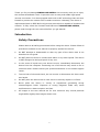
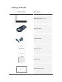
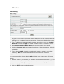
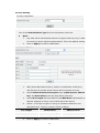
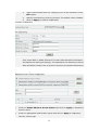
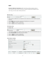
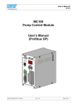
CNP-WF514
Wireless Broadband Router
User Manual
1
Table of Contents
INTRODUCTION ..............................................................................................................................4
SAFETY PRECAUTIONS ...................................................................................................................4
PACKAGE CONTENTS .......................................................................................................................5
HARDWARE OVERVIEW ..................................................................................................................6
GETTING STARTED ........................................................................................................................7
CONNECTING TO DEVICE ...............................................................................................................7
WINDOWS XP SETUP .....................................................................................................................7
WINDOWS VISTA SETUP ...............................................................................................................8
WINDOWS 2000 SETUP ...............................................................................................................8
WINDOWS 98/ME SETUP ............................................................................................................8
DEVICE CONFIGURATION .......................................................................................................10
INTERNET CONNECTION WIZARD ............................................................................................. 11
STATUS.............................................................................................................................................17
WAN SETUP ...................................................................................................................................19
Dynamic IP Setting ...........................................................................................................19
PPPoE Setting.......................................................................................................................20
Static IP Setting..................................................................................................................21
PPTP Setting .........................................................................................................................21
L2TP Setting ..........................................................................................................................22
LAN SETUP .....................................................................................................................................23
WIRELESS .......................................................................................................................................25
Basic Setting .........................................................................................................................25
Security Setting...................................................................................................................26
Filter List Setting................................................................................................................28
WDS Setting ..........................................................................................................................29
WDS Setting ..........................................................................................................................29
Association Table ...............................................................................................................30
ROUTING .........................................................................................................................................30
NAT..................................................................................................................................................31
DMZ Host Setup...................................................................................................................31
FTP Private Port ..................................................................................................................31
Virtual Server Setup .........................................................................................................31
Port Triggering ....................................................................................................................32
FIREWALL ........................................................................................................................................33
2
MAC Filtering Configuration.........................................................................................33
Connection Filtering Configuration..........................................................................34
URL Filtering Configuration..........................................................................................35
Ping Filtering Configuration.........................................................................................35
SPI FIREWALL ...............................................................................................................................35
DDNS ..............................................................................................................................................36
MISC ...............................................................................................................................................37
Login ID & Password Setup .........................................................................................37
Remote Management .......................................................................................................37
UPnP Setup ............................................................................................................................38
System Time Setup ...........................................................................................................38
WAN Link Status & Setup ..............................................................................................38
Restore Default/Restart System...............................................................................39
Firmware Upgrade.............................................................................................................39
TROUBLESHOOTING...................................................................................................................40
APPENDIX ........................................................................................................................................41
TECHNICAL SPECIFICATIONS .....................................................................................................41
3
Thank you for purchasing CANYON CNP-WF514. We sincerely wish you to enjoy
the wireless broadband router. It provides user an easy and stable high speed
internet connection. It is also equipped with built-in NAT technology that acts as a
firewall to protect the network from outside intrusions. Ultimately, the device is
implemented with an IEEE 802.11b/g access point which is capable of wireless LAN
network. To fully utilize the functions and features of CANYON CNP-WF514,
please read through the user manual before you get started.
Introduction
Safety Precautions
Please observe all safety precautions before using the device. Please follow all
procedures outlined in this manual to properly operate the device.
z
Do NOT attempt to disassemble or alter any part of the device that is not
described in this guide.
z
Do NOT place the device in contact with water or any other liquids. The device
is NOT designed to be liquid proof of any sort.
z
In the event of liquid entry into device interior, immediately disconnect the
device from the computer. Continuing use of the device may result in fire or
electrical shock. Please consult your product distributor or the closest support
center.
z
To avoid risk of electrical shock, do not connect or disconnect the device with
wet hands.
z
Do NOT place the device near a heat source or directly expose it to flame.
z
Never place the device in vicinity of equipments generating strong
electromagnetic fields. Exposure to strong magnetic fields may cause
malfunctions or data corruption and loss.
z
All images in the user manual are for user reference only. Actual products
might differ slightly than images shown here.
4
Package Contents
Product Image
Item Name
CNP-WF514 Main Unit
Standing Base
Power Adapter
Warranty Card
Quick Guide
Documentation CD
5
Hardware Overview
SYS
PC1/PC2/
WAN
PC3/PC4
SYS
Power status indicator
WAN
WAN interface status indicator
PC1/PC2/PC3/PC4
LAN interface status indicator
Antenna
PC1/PC2/
DC Jack
DC Jack
WAN
PC1/PC2/PC3/PC4
Default
Antenna
WAN
PC3/PC4
Default
Connects to power adapter
Connects to cable/DSL modem or other Ethernet devices
Connects to LAN port on PC or other Ethernet devices
Reset device to factory default settings
Transmits signals
6
Getting Started
Connecting to Device
Please follow the steps below to connect the modem and PC(s) with CANYON
CNP-WF514:
1.
Begin by searching for an appropriate location to setup device. Please keep
in mind to keep the device in the center of working area as the signal
strength and data transfer rate falls off with distance.
2.
It is also recommended to place device at a higher position to ensure
minimum obstacle interference.
3.
Make sure that all network devices are powered off, including the device
itself, PCs, switches, cable or DSL modem, and other peripherals.
4.
Connect the modem to WAN port of the device by one CAT 5 Ethernet
cable.
5.
Connect PC(s) with the LAN ports (PC1/PC2/PC3/PC4) of the device by CAT
5 Ethernet cables. One PC connects to only one port using one cable.
6.
Power on the cable or DSL modem.
7.
Plug in the power of the device. The Power status indicator at the front
panel of device will light up as soon as the power adapter is connected
properly.
8.
Power on PC(s).
Windows XP Setup
1.
Click on Start Æ Settings Æ Control Panel.
2.
Click on Network and Internet Connections icon.
3.
Click on Network Connections
4.
Right click on Local Area Connection icon and click on Properties.
5.
Select TCP/IP option and click on Properties. The Properties dialog box will
be displayed.
6.
Check “Obtain an IP address automatically” and “Obtain DNS server
address automatically” options.
7.
Click Ok to confirm modifications.
7
Windows Vista Setup
1.
Click on Start Æ Settings Æ Network Connections.
2.
Right click on Local Area Connection icon and click on Properties.
3.
Click on Continue in User Account Control dialog box.
4.
Select TCP/IPv4 option and click on Properties. The Properties dialog box
will be displayed.
5.
Check “Obtain an IP address automatically” and “Obtain DNS server
address automatically” options.
6.
Click Ok to confirm modifications.
Windows 2000 Setup
1.
Click on Start Æ Settings Æ Control Panel.
2.
Double click on Network and Dial-up Connections icon. The Network dialog
box will be displayed.
3.
Right click on Local Area Connection icon and click on Properties.
4.
Select TCP/IP option and click on Properties. The Properties dialog box will
be displayed.
5.
Check “Obtain an IP address automatically” and “Obtain DNS server
address automatically” options.
6.
Click Ok to confirm modifications.
Windows 98/ME Setup
1.
Click on Start Æ Settings Æ Control Panel.
2.
Double click on Network icon. The Network dialog box will be displayed.
3.
Please make sure that appropriate network card is installed before
proceeding. Click on the Configuration label.
4.
Select TCP/IP option and click on Properties. The Properties dialog box will
be displayed.
NOTE:
Select the TCP/IP item with an arrow “Æ” pointing to the network card if more
than one TCP/IP options is present.
5.
Make sure that the option “Obtain IP address automatically” is checked.
6.
Make sure that the “WINS Resolution” option is checked under WINS
Configuration dialog box.
7.
From Gateway dialog box, remove all entries from the Installed gateways
8
by selecting them and clicking on Remove.
8.
From DNS Configuration dialog box, remove all entries from DNS server
search order box and Domain suffix search order box by selecting them
and clicking on Remove. Click on Disable DNS.
9.
Click Ok to confirm modifications.
NOTE:
To access the device via a wireless connection, PC must be equipped with
802.11b or 802.11g wireless adapter/PCI card. The configuration should be set
as below:
z
Operation Mode: Infrastructure
z
SSID: Default
z
Authentication: Disabled
z
Encryption: Off
9
Device Configuration
Before setting up the device, please make sure that the host PC(s) is set on the IP
sub-network accessible by CANYON CNP-WF514 device. The default network
address of the device is set as 192.168.1.1. Please configure IP address of host PC
at 192.168.1.XXX where XXX is a number between 002 and 254. The subnet mask
should be 255.255.255.0. Please follow below steps to enter web browser
management mode.
1.
Open a browser
(Internet Explorer
browser only) and
type in “192.168.1.1”
at the address bar and
press Enter.
2.
Type “guest” at the
user name text box
and “guest” again at
the password text box.
3.
The home page of web
browser management
mode will be displayed.
4.
Click on 8 different
functions on the main
router menu on the
left. The corresponding
information will be
displayed at right.
5.
Click on Help at any
time to bring up help
menu.
NOTE:
The factory settings of user name and the password are by default “guest”. It is
recommended that user change that information to better maintain network
security.
10
Internet Connection Wizard
1.
Start Internet Configuration Wizard
Internet Configuration Wizard will pop up upon successful login.
z
NOTE:
In order to enter Wizard mode, temporarily disable popup window blocking
option if necessary or click on Wizard to start.
Select pop up to enable automatic Internet Configuration Wizard prompt
z
window. Click on Save to save this setting.
Click on Start to continue or Click on Exit to exit.
z
2.
Select Connection Type
11
z
Select 1 of 7 connection types instructed by ISP or network administrator.
z
Click on Next to continue or Prev to go back to previous page.
z
Click on Exit to exit.
2.1
DHCP Connection
z
Click on Clone MAC or type in MAC address if required by ISP.
z
Click on Default MAC to restore to default MAC address.
z
Click on Next to continue or Prev to go back to previous page.
z
Click on Exit to exit.
2.2
PPPoE Connection
12
z
Type in PPPoE Account and PPPoE Password provided from ISP.
z
Click on Next to continue or Prev to go back to previous page.
z
Click on Exit to exit.
2.3
z
Static IP Connection
Type in IP Address, Subnet Mask, Gateway, Primary DNS, and
Secondary DNS provided from ISP.
z
Click on Next to continue or Prev to go back to previous page.
z
Click on Exit to exit.
2.4
PPTP DHCP Connection
13
z
Type in PPTP User Name, PPTP Password, Server IP Address, Primary
DNS, and Secondary DNS provided from ISP.
z
Click on Next to continue or Prev to go back to previous page.
z
Click on Exit to exit.
2.5
z
PPTP Static IP Connection
Type in PPTP User Name, PPTP Password, Server IP Address, Subnet
Mask, Gateway, Primary DNS, and Secondary DNS provided from ISP.
z
Click on Next to continue or Prev to go back to previous page.
z
Click on Exit to exit.
2.6
L2TP DHCP Connection
14
Type in L2TP User Name, L2TP Password, Server IP Address, Primary
z
DNS, and Secondary DNS provided from ISP.
z
Click on Next to continue or Prev to go back to previous page.
z
Click on Exit to exit.
2.7
L2TP Static IP Connection
Type in L2TP User Name, L2TP Password, Server IP Address, Subnet
z
Mask, Gateway, Primary DNS, and Secondary DNS provided from ISP.
z
Click on Next to continue or Prev to go back to previous page.
z
Click on Exit to exit.
3.
Wireless AP Configuration
15
Select a Radio Band type from the drop down box. (802.11b/g is
z
recommended)
z
Select Radio Mode from the drop down box. (AP+WDS is recommended)
z
Type in SSID as desired. (SSID must be identical in all devices connecting to
device)
Select a broadcasting channel from drop down box. (Device is set on channel
z
6 by default)
z
Click on Next to continue or Prev to go back to previous page.
z
Click on Exit to exit.
4.
z
Installation Completed
Click on Exit to finish Internet Configuration Wizard.
16
Status
1.
This section displays various router information divided into 3 tabs.
2.
The 1st tab displays parameters of WAN/LAN/Wireless connection, and System
Info.
z
WAN Status: WAN interface parameters of the device.
NOTE:
Click on Connect to refresh IP address with DHCP connection type and to initiate
a dial up connection with PPPoE connection type.
z
LAN Status: LAN interface parameters of the device.
z
Wireless Status: WLAN interface parameters of the device.
z
System Info: Displays device firmware version.
17
3.
The 2nd tab displays statistics of packets from WAN port. Click on Refresh to
update data monitor table to receive most recent data.
z
System Run Time: Displays system run time from last system restart.
z
Statistics: Monitors current sent/received packets through both wireless and
wired connection.
4.
The 3rd tab displays system logs including system events, network abnormalities.
18
WAN Setup
1.
This section assists user to setup network connection types and their subsidiary
functions. The default setting is Dynamic IP connection type.
2.
Click on Save to save modified settings.
Dynamic IP Setting
1.
Click on Dynamic IP User (Cable Modem) option.
2.
Click on Clone MAC to replace current device MAC address with host PC MAC
address. Click on Default MAC to restore to default.
3.
Enter MTU (Maximum Transmission Unit) value if required. The default value is
set at 1496.
19
NOTE:
It is recommended to set MTU value between 1200 and 1500 range.
4.
Enter Primary DNS and Secondary DNS IP address if required by ISP provider.
5.
Click on Apply to confirm modifications.
6.
Click on Save to save modified settings.
PPPoE Setting
1.
Click on PPPoE User (ADSL) option.
2.
Type in PPPoE Account and PPPoE Password provided from ISP.
3.
Click on MAC Clone to replace current device MAC address with host PC MAC
address. Click on Default MAC to restore to default.
4.
Enter MTU (Maximum Transmission Unit) value if required. The default value is
set at 1496.
NOTE:
It is recommended to set MTU value between 1200 and 1500 range.
5.
Enter Primary DNS and Secondary DNS IP address if required by ISP provider.
6.
Select a connection mode if necessary. The default setting is “Connect to
Internet automatically”.
7.
Click on Apply to confirm modifications.
8.
Click on Save to save modified settings.
20
Static IP Setting
1.
Type in WAN IP Address, Subnet Mask, Default Gateway, Primary DNS
and Secondary DNS address provided by ISP.
2.
Click on MAC Clone to replace current device MAC address with host PC MAC
address. Click on Default MAC to restore to default.
3.
Enter MTU (Maximum Transmission Unit) value if required. The default value is
set at 1496.
NOTE:
It is recommended to set MTU value between 1200 and 1500 range.
4.
Click on Apply to confirm modifications.
5.
Click on Save to save modified settings.
PPTP Setting
21
1.
Type in User Name and Password provided by ISP.
2.
Type in PPTP Server IP Address.
3.
Select connection type. Please follow instructions from ISP. Enter Static WAN IP
Address/Subnet Mask/Gateway if necessary.
4.
Enter Primary DNS and Secondary DNS IP address if required by ISP provider.
5.
Enter MTU (Maximum Transmission Unit) value if required. The default value is
set at 1496.
NOTE:
It is recommended to set MTU value between 1200 and 1500 range.
6.
Click on Apply to confirm modifications.
7.
Click on Save to save modified settings.
L2TP Setting
Dial-up users typically use the PPP (Point-to-Point Protocol) for an Internet
connection. PPP is a layer 2 protocol that frames data so it can be sent across a
dial-up connection. The protocol allows users to run TCP/IP software such as Web
browsers as if they were directly connected to the Internet. In fact, user TCP/IP
packets are put into PPP frames for transport across the dial-up link to an ISP. The ISP
then extracts the TCP/IP packets and forwards them on the Internet. L2TP enhances
PPP by granting a means for a remote user to extend a PPP link across the Internet all
the way to a corporate site. In essence, a tunnel is established across the Internet
from the ISP to a corporate site and frames are transmitted through the tunnel. Once
the tunnel is set up, the ISP is essentially out of the picture and the user
communicates to the corporate network over what appears to be a direct dial-up
connection.
22
1.
Type in User Name and Password provided by ISP.
2.
Type in PPTP Server IP Address.
3.
Select connection type. Please follow instructions from ISP. Enter Static WAN IP
Address/Subnet Mask/Gateway if necessary.
4.
Enter Primary DNS and Secondary DNS IP address if required by ISP provider.
5.
Enter MTU (Maximum Transmission Unit) value if required. The default value is
set at 1496.
NOTE:
It is recommended to set MTU value between 1200 and 1500 range.
6.
Click on Apply to confirm modifications.
7.
Click on Save to save modified settings.
LAN Setup
1.
This section assists user to designate a specific IP address to the device and
other IP addresses to PC(s) or network machines connected to the device. The
section is divided into 2 tabs.
23
2.
The 1st tab configures PC(s) connected to device and other settings. Type in
System IP Address of device LAN port IP address. This is the default gateway
IP address of LAN client(s)/host PC(s).
3.
Type in Subnet Mask of the device LAN segment.
4.
Enable/disable DHCP Server function by clicking on the option. Enabling DHCP
Server function allows the device to assign host PC(s) IP address. DHCP IP
address range can be allocated by entering range of IP addresses under DHCP
IP Pool option.
5.
Click on Apply to confirm modification.
NOTE:
User must manually assign IP address of host PC(s) if DHCP Server on option is
disabled.
1.
Reserve a specific DHCP IP Address to a PC or network device by typing the
client’s MAC address and desired IP segment. Click Add to confirm.
2.
A Designated IP Table below displays all DHCP IP address reserved. Select an IP
address and click on Delete to remove it from table.
3.
Click on Save to save modified settings.
1.
The 2nd tab displays all PC(s) connected to the device.
24
Wireless
Basic Setting
1.
This section assists user to create a network environment that connects wireless
PC(s) to a wired LAN. It also allows wireless stations to access network resources
and share the broadband Internet connection. The section is divided into 6 tabs.
2.
The 1st tab defines basic settings for wireless networking. Check on Disabled
Wireless and click on Apply to disable wireless function. Uncheck to restore.
3.
Select Radio Band and Radio Mode from the drop down menu boxes.
4.
Check on Booster Mode to increase throughput of data transmission. Uncheck
to disable.
5.
Type in desired SSID (network name shared among all points in a wireless
network). SSID is case sensitive and must not exceed 32 characters.
NOTE:
It is recommended to change default SSID (default) to a unique name for better
security.
6.
Select a channel (14 channels) for wireless communication. Channels 1, 6, and
11 are non-overlapping channels while all others are overlapping channels.
7.
Click on Apply to confirm modification.
8.
Click on Save to save modified settings.
25
Security Setting
The 2nd tab defines all common security settings for wireless networking. Select
one of the Authentication Type from the drop down menu box.
z
None:
1.
Any data will be transmitted without encryption and any PC(s) is able
to connect to device without authentication. This is the default setting.
2.
z
Click on Apply to confirm modification.
WEP:
1.
WEP (Wired Equivalent Privacy) utilizes a combination of 64-bit or
128-bit keys to provide access control and encryption security.
2.
Select Authentication & Encryption type (Open System, Shared
Key, and Auto Select) from the drop down menu box.
3.
Select KEY Length (64 bits/128 bits) and WEP Mode (HEX/ASCII) as
desired. Settings on PC(s) must match that of the device.
4.
Select 1 of 4 keys to type in a string of characters defined in the
description box. The key criteria is listed as below:
Key Length
HEX Format
ASCII Format
64 bit
10 hexadecimal digits
5 ASCII characters
128 bit
26 hexadecimal digits
13 ASCII characters
5.
Click on Apply to confirm modification.
26
z
WPA Personal:
1.
WPA (Wi-Fi Protected Access) is an advanced security standard that
utilizes pre-shared key to authenticate wireless stations and encrypt
data during communications.
2.
Select Authentication & Encryption type (TKIP and AES) from the
drop down menu box.
3.
Type in Pass Phrase with size ranging from 8 to 63 characters under
KEY option.
4.
Specify time WPA key must be renewed. The default value is 86400.
5.
Click on Apply to confirm modification.
NOTE:
TKIP (Temporal Key Integrity Protocol) utilizes a stronger encryption
algorithm and includes Message Integrity Code while AES (Advanced
Encryption System) utilizes a symmetric 128 bit block data encryption, the
strongest encryption currently available.
z
WPA2 Personal
1.
WPA2 is a more advanced version of WPA which only authenticates
access and encrypts data transmission with AES type.
27
2.
Type in Pass Phrase with size ranging from 8 to 63 characters under
KEY option.
z
3.
Specify time WPA key must be renewed. The default value is 86400.
4.
Click on Apply to confirm modification.
WPA&WPA2 Personal:
Auto-select WPA or WPA2 detects PC wireless authentication information
and adjusts its setting accordingly. The operations are identical to that of
WPA and WPA2. Please refer to previous sections for detailed information.
Filter List Setting
1.
The 3rd tab specifies wireless access control based on MAC address of PC(s).
2.
Check on Enable Wireless Access Control and click on Apply to implement
access control.
3.
Check on appropriate radio button option and click on Apply to implement
security control type.
28
4.
Type in MAC address of PC(s) and optional comments if necessary under
Descript box. Click on Add to edit modified rule.
5.
An Access Control Table below displays all PC(s) under access control on the
network. Select a rule and click on Delete to remove it from table.
6.
Click on Save to save modified settings.
WDS Setting
1.
The 4th tab creates wireless bridge between 2 or more router device.
2.
Type in MAC address of other router device(s) and optional comments if
necessary under Descript box. Click on Add to edit modified rule.
3.
A Wireless Bridge Information Table below displays all router devices bridged on
the network. Select a router device and click on Delete to remove it from table.
4.
Click on Save to save modified settings.
WDS Setting
1.
The 5th tab adjusts advanced wireless function.
2.
Type in the Beacon Interval between each beacon broadcast. A beacon is a
packet broadcasted by the device to assist in network synchronization. The
default value is 100.
3.
Type in RTS Threshold value as desired between 256 and 2432. The default
value of 2347 should only be modified when encountering inconsistent data flow.
29
4.
Type in DTIM Interval frequency between each DTIM (Delivery Traffic
Indication Message) broadcast. Lower value result in more efficient networking
while preventing PC(s) from entering power saving mode. Higher value
interferes with wireless transmission yet allowing PC(s) to enter sleep mode thus
saving power consumption.
5.
Select maximum Transmit Rate (Transmission rate of data packets)of the
device. The default value is Auto.
6.
Select Preamble Type (Length of CRC block in the frames during wireless
communication). Short Preamble is appropriate for heavy traffic wireless
network while Long Preamble provides better communication reliability.
7.
Select 802.11g Protection type between CTS, RTS/CTS, or disabled.
8.
Click on Apply to confirm modification.
9.
Click on Save to save modified settings.
Association Table
1.
The 6th tab displays all PC(s) connected to device via wireless network.
2.
Click on Refresh to update table.
Routing
1.
This section assists user to create static route(s) between network and device.
2.
Select Route Type and type in Target IP address, Subnet Mask, and Gateway
IP. Click on Add to add routing information.
3.
A Routing Table below displays all static routing paths. Select a routing path and
click on Delete to remove it from table.
4.
Click on Save to save modified settings.
30
NAT
Network Address Translation (NAT) technology allows multiple users at
local network to gain access to Internet through a single public IP address while
user PC(s) are still under firewall protection.
DMZ Host Setup
1.
DMZ function enables PC to be exposed to the Internet for use of special purpose
services.
2.
Check DMZ option and enter desired PC IP address to be exposed.
3.
Click on Apply to confirm modification.
4.
Click on Save to save modified settings.
FTP Private Port
1.
FTP function enables File Transfer Protocol which does not use the standard port 21.
2.
Check Port Number and enter the port number.
3.
Click on Apply to confirm modification.
4.
Click on Save to save modified settings.
Virtual Server Setup
31
1.
Virtual server allows PC(s) located outside of network to be able to access services on
PC(s) connected to the device.
2.
Type in the description of the rule desired under Rule Name.
3.
Type in internal IP address of the client PC(s) desired for public port number packet
access.
4.
Select the Protocol type including TCP, UDP, FTP, HTTP, HTTPS, POP3, SMTP, DNS,
TELNET, IPSEC, and PPTP.
5.
Enter External Port number that the public port number will be changed to when the
packet enters the network.
6.
Enter Internal Port number from the Internet that will be redirected to the private IP
address in the network.
7.
Click on Add to add modified rule.
8.
A Virtual Server Table below displays all valid virtual servers available on the network.
Select a rule and click on Delete to remove it from table.
9.
Click on Save to save modified settings.
Port Triggering
1.
Port Triggering function commands router to remember outgoing data for specific port
numbers, recalls the matching requested data, and pulls the data back to the proper
PC(s) by its IP address and port mapping rules.
2.
Select one of the predefined rules or type in the description of the service desired
under Rule Name.
3.
Select outbound port protocol type between TCP and UDP under Trigger Protocol.
4.
Type in all of the outbound range of port numbers. Port numbers are separated by
comma. Use a dash in between port numbers to define a range of port numbers.
32
5.
Select inbound port protocol type between TCP and UDP under Forward Protocol.
6.
Type in all of the inbound range of port numbers. Port numbers are separated by
comma.
7.
Click on Add to add modified rule.
8.
A Trigger Port Table below displays all valid trigger rules available on the network.
Select a rule and click on Delete to remove it from table.
9.
Click on Save to save modified settings.
Firewall
The device provides extensive firewall protections by restricting connection
parameters to limit the risk of attacks and creates packet filtering rules by
restricting service ports, IP address or MAC address.
MAC Filtering Configuration
1.
MAC Filtering function blocks certain PC(s) from Internet access based on MAC
addresses.
2.
Click on Start/Stop to turn on/off the MAC filtering configuration.
3.
Check the option to allow all other PC(s) whose MAC address(es) are not on the list to
be permitted of Internet access.
4.
Type in MAC address (in format of XX-XX-XX-XX-XX-XX) of desired PC and select
Permit/Deny to manage its Internet accessibility. Click Add to add modified rule.
5.
A MAC Filtering Table below displays all valid MAC filtering rules available on the
network. Select a rule and click on Delete to remove it from table.
6.
Click on Save to save modified settings.
33
Connection Filtering Configuration
1.
Connection Filtering function blocks certain PC(s) from Internet access based on time.
2.
Click on Start/Stop to turn on/off the MAC filtering configuration.
3.
Check the option to allow all other PC(s) whose IP address(es) are not on the list to be
permitted of Internet access.
4.
Type in the description of the rule desired under Rule Name.
5.
Type in source IP address desired to apply this access control rule.
6.
Select protocol type including TCP, UDP, FTP, HTTP, and ALL.
7.
Type in a range of port numbers to block corresponding PC(s) from accessing Internet.
8.
Select days and/or time to apply this access control rule. Click Add to add modified
rule.
9.
An Access Control Table below displays all valid access control rules available on the
network. Select a rule and click on Delete to remove it from table.
10. Click on Save to save modified settings.
34
URL Filtering Configuration
1.
URL Filtering function blocks certain website accesses by specifying keywords.
2.
Type in keywords to block PC(s) from accessing Internet websites. Wildcards such as
“*” (a string of characters) or “?” (a single character) are available. Click Add to add
modified rule.
3.
A Keyword filtering Table below displays all valid keyword rules available on the
network. Select a rule and click on Delete to remove it from table.
4.
Click on Save to save modified settings.
Ping Filtering Configuration
1.
Ping Filtering function rejects ping requests from other devices.
2.
Check on one or both options to Discard ping request from WAN/LAN interface.
3.
Click on Apply to confirm modification.
4.
Click on Save to save modified settings.
SPI Firewall
SPI (Stateful Packet Inspection) Firewall enhances data security in a network
environment more efficiently and effectively by examining additional
characteristics of data packets and applying logical analysis.
35
1.
Check on Set SPI Firewall State and click Apply to activate SPI Firewall function.
2.
Check on Limit the max session of the host and specify its maximum session value
to limit network sessions. Click on Apply to confirm modifications.
3.
Check on Limit the max unfinish session of the host and specify its maximum
unfinished session value to limit unfinished network sessions. Click on Apply to
confirm modifications.
4.
Check on The host created NAT sessions exceeding ___ in ___ seconds and
specify session value and time period to limit NAT sessions in designated time period.
5.
Check on The host send bytes exceeding ___ (Kbytes) in ___ seconds and
specify total data amount and time period to limit NAT sessions in designated amount
of data transmission. Click on Apply to confirm modifications.
6.
Check on Lock of the host and specify number of seconds to prohibit visits from
illegal hosts for a user specified time duration.
7.
Check on Record to system log and click on Apply to record events on system log.
8.
Click on Apply to confirm modification.
9.
Click on Save to save modified settings.
DDNS
Dynamic Domain Name System (DDNS) maps the static domain name to a
dynamic IP address. Account, password, static domain name must be obtained
from DDNS service provider.
36
1.
Click on Start/Stop to turn on/off DynDNS Operation.
NOTE:
User must sign up on www.dyndns.org to obtain DynDNS service before starting.
2.
Type in account name, password, and domain obtained from DDNS provider.
3.
Click Apply to confirm modification and Refresh to display most recent update.
4.
Click on Save to save modified settings.
MISC
Login ID & Password Setup
1.
The default Login ID is “guest” and the default password is also “guest”.
2.
To change password, type in new password and type in the same new password again
to confirm.
3.
Click Apply to confirm modifications.
4.
Click on Save to save modified settings.
NOTE:
To reset device to factory default setting, press RESET button on the device front panel. The
Login ID and password will be reset to “guest”.
Remote Management
37
1.
The Remote Management function allows user to manage the device through Internet
from a remote location.
2.
Check Management Port option and type in the corresponding port number.
3.
Click Apply to confirm modifications.
4.
Click on Save to save modified settings.
NOTE:
To access web based management page, simply type in http://<WAN IP Address>:8080
(for example: http://192.168.1.8:8080).
UPnP Setup
1.
The UPnP function exposes the device on the Intranet (internal) network. PC(s)
connected to the device does not require further configuration to access the network.
2.
Check Enable UPnP Server option.
3.
Click Apply to confirm modifications.
4.
Click on Save to save modified settings.
System Time Setup
1.
The System Time Setup function configures device time.
2.
Select one of the time zones from the drop down menu.
3.
Click Apply to confirm modifications.
4.
Click on Save to save modified settings.
WAN Link Status & Setup
1.
The WAN Setup function configures device connection bandwidth.
2.
Select one of the connection bandwidth from the drop down menu.
3.
Click Apply to confirm modifications.
4.
Click on Save to save modified settings.
38
Restore Default/Restart System
1.
Click on Restore Default to restore all device settings to factory setting.
2.
Click on Restart System to reboot the device.
Firmware Upgrade
1.
Click on Browse to locate firmware file on host PC.
2.
Click Apply to confirm modifications.
NOTE:
Press briefly on Default button to reset the device. Press and hold the button for at
least 5 seconds to restore device to factory default settings.
39
Troubleshooting
Please refer to the following procedures if CNP-WF514 does not function as it
should be. Be advised that the following instructions are only intended for simply
troubleshooting purpose. Please contact your local authorized shops for further
troubleshooting and technical support.
z
Do not remember password.
1.
Press and hold the reset button on the front panel of device for more than
5 seconds.
2.
z
Unplug power adapter and wait for 5 seconds before plugging it in again.
Device malfunctioning with cable/DSL modem connection.
1.
Please check signal stability from cable/DSL modem. There should be a
signal indicator on the modem displaying its connection status. Contact
ISP if the signal is bad.
2.
Please check status indicators on the front panel of device. When working
properly, the SYS indicator should be solid and the WAN indicator should
be blinking. The LAN indicator(s) should also be blinking with
corresponding PC(s) connect to the device.
z
3.
Please verify that the network cables are working properly.
4.
Enable DHCP server function. Please refer to LAN setup section
5.
Reset the device as described at above section if all else failed.
Setup PC(s) to obtain IP address manually.
The below instructions only refer to Windows XP verison OS only. Please refer
to OS manufacturer for other OS
1.
Click on Start Æ Settings Æ Control Panel.
2.
Click on Network and Internet Connections and then Network
Connections.
3.
Right click on Local Area Connection icon and select Properties.
4.
Highlight Internet Protocol (TCP/IP) item and click on Properties.
5.
Type in the following information on the corresponding properites:
z
IP address: 192.168.1.XXX where XXX is a number between 2 and
253.
6.
z
Subnet mask: 255.255.255.0
z
Default gateway: 192.168.1.1
z
Preferred DNS server: 192.168.1.1
z
Alternate DNS server: leave this property blank.
Click on OK to confirm modifications.
40
Appendix
Technical Specifications
Standards
IEEE 802.3, IEEE 802.3u, IEEE 802.11g,
IEEE802.11b
Channels
13 Channels
Management Interface
Web Based
Network Ports
WAN: 1 X 10/100 RJ-45 Port
LAN: 4 X 10/100 RJ-45 Ports (with switching function)
Cabling Type
Cat 5 Ethernet Network Cable
RF Power Output
15 ± 2dBm
Wireless Security
WPA/WPA2, WEP 64/128bit, Wireless MAC Filtering
LED Indicators
SYS, WLAN, LAN Link/Activity, WAN
Temperature
Operating: 0° to 40° C
Storage: -20° to 70° C
Humidity
Operating: 10% to 85 % non-condensing
Storage: 5% to 90 % non-condensing
Dimensions
135mm(L) X 95.4mm(W) X 28mm(H)
Weight
210g
Power
DC 9V, 700mA
41