1
K 0 1" i: S S I 0 i\ A I.
s !•: K I !• s
iTM
KB 101
USER'S GUIDE
^JCeyTroimDC
Notices
The infomiation contained in the KB 101 User's
Guide is the property of Key Tronic Corporation and
may not be copied, photocopied, reproduced,
translated or reduced to any electronic inedium or
machine-readable form without prior written consent
from Key Tronic Corporation.
Trademark Notices
PC/XT™ and Personal Systeni/2™ are trademarks
and IBM® and PC AT® are registered trademarks of
Intemational Business Machines Corporation.
Amstrad™ is a trademark of Amstrad Pic.
KB 101™ is a trademark and Key Tronic® and Key
Tronic Professional Series® are registered trademarks of Key Tronic Corporation.
Lotus® and 1-2-3® are registered trademarks of
Lotus Development Corporation.
WordStar® is a registered trademark of MicroPro
Intemational Corporation.
KB 101 User's Guide
Part Number: KTC 31310-2
Comments or correspondence regarding the KB 101
User's Guide should be directed to:
Key Tronic Corp.
P.O. Box 14687
Attn: Mktg. Communications
Spokane, WA 99214-0687
Copyright © 1988, 1991
by Key Tronic Corporation. All rights reserved.
Warning
This equipment generates and uses radio frequency
energy and if not installed properly, that is in
strict accordance with the manufacturer's instructions, may cause interference to radio and television
reception. It has been type-tested and found to
comply with the limits for a Class B computing
device in accordance with the specifications in CFR
47, Part 15, Subpart B ofthe FCC Rules, which are
designed to provide reasonable protection against
interference in a residential installation. However,
there is no guarantee that interference will not occur
in a particular installation. If this equipment does
cause interference to radio or television reception,
which can be determined by tuming the equipment
on and off, the user is encouraged to try to correct the
interference by one or more of the following measures:
•
Reorient the receiving antenna.
•
Relocate the computer with respect to the
receiver.
•
Move the computer away from the receiver.
•
Plug the computer and receiver into a
different outlet so that the computer and
receiver are on different branch circuits.
•
Move the cables connected to the computer
to minimize the interference.
Warning
If necessary the user should consult the dealer or an
experienced radio/television technician for additional
suggestions. The user may find the following booklet,
prepared by the Federal Communications Commission, helpful:
"How to Identify and Resolve Radio-TV Interference
Problems."
This booklet is available from the U.S. Govemment
Printing Office, Washington, D.C. 20402, Stock No.
004-000-00345-4.
Warning
Any changes or modifications not expressly
approved by the party responsible for compliance,
could void the user's authority to operate this
equipment.
This equipment is supplied with a shielded cable to
meet FCC Class "B" emission limits.
"THIS DIGITAL APPARATUS DOES NOT EXCEED
THE CLASS "B" LIMITS FOR RADIO NOISE EMISSIONS SET OUT INTOERADIO INTERFERENCE
REGULATIONS OFTOECANADIAN DEPARTMENT
OF COMMUNICATIONS."
"LE PRESENT APPAREIL NUMERIQUE N"6MET PAS
DE BRUITS RADIO^LECTRIQUES DEPASSANT LES
LIMITES APPLICABLES AUX APPAREILS
NUMERIQUES DE LA CLASSE "B" PRESCRITES
DANS LE REGLfeMENT SUR LE BROUILLAGE
RADIOELECTRIQUE I^DICTE PAR LE MINIST^RE
DES COMMUNICATIONS DU CANADA."
Ill
Table of Contents
Section 1
Introduction
Keyboard Description
Features
User's Guide Overview
User's Guide Conventions
Section 2i
Installation
Preliminary Steps
Keyboard Installation
Mode Switch Settings
Section 3
3-1
3-2
3-4
3-5
3-7
3-8
3-11
Keyboard Maintenance
Cleaning the Keyboard
Keyboard Protection Accessories
Modifying the Key Feel
IV
2-1
2-2
2-5
Using the Keyboard
Keyboard Organization
Function Key Area
LED Panel
Numeric Keypad
Cursor Control Keypad
Typewriter Area
Keyboard Height Adjustment
Section
1-1
1-3
1-4
1-5
4-1
4-1
4-2
List of Appendices
Appendix A
Technical Information
Keyboard Interface Information
Scan Code Processing
PC/XT Scan Codes
AT Scan Codes
Keyboard Specifications
Appendix B
Customer Support Information
Technical Assistance
Retum for Repair Procedure
Limited Warranty
Appendix C
A-1
A-2
A-3
A-4
A-5
B-1
B-3
B-5
Glossary
Glossary Listing
C-1
Section 1
INTRODUCTION
Section 1 provides a description and a list of standard
features for the Key Tronic® KB 101™ Professional
Series® keyboard. An overview of the User's Guide and
conventions used are also presented.
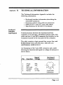
Keyboard
Description
The KB 101 Professional Series™ keyboard is a plugcompatible replacement for the IBM PC™, XT™ and
AT* Personal Computer keyboards (standard and
enhanced), as well as most IBM* compatibles.
Installation is simply a matter of unplugging your
existing keyboard and plugging in the KB 101. The
KB 101 is switch selectable from XT to AT.
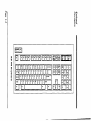
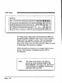
The KB 101 uses the industry-standard 101 key layout
and features a smaller enclosure that takes up less desk
space than other conventional size keyboards. Keys are
placed in easy-to-find locations and keycaps are clearly
marked with familiar key legends rather than symbols.
Ctrl and Alt keys on each side of the space bar provide
additional convenience.
Function keys Fl through F12 and the Escape key are
placed on the top row for easier access and more accurate
operation. Also together in the top row are special
function keys: Print Screen, Scroll Lock, and Pause.
An LED panel in the upper right-hand comer of the
keyboard contains status indicators for the Num Lock,
Caps Lock, and Scroll Lock keys. In addition to the
numeric keypad, a separate cursor control keypad is
added with dedicated keys for screen control and cursor
movement.
An illustration ofthe KB 101 keyboard is shown on the
next page.
Page 1-1
53 >!
I
00
keytronfc' K i t o i " !
;v.i,-s.i,.ii,il.s.M,'.'l
Bl BBHBI B B B B B B B B
-
jl
1@
»
»
*
1 1
1 2
3
4
5
1E
|R
n
T.. i?;,| 0
ota
CV.L.CII
A
onn
1 Z
1
Ctrl
1 w
S
1
All
D
X
y
0
F
C
l: M? 11 Hi 1^ : l ~
r
V
u
H
B
1
J
N
10
1
K
M
p
L
«
(
[
:
»
?
All
1
1
1
\
<_,Em,
os„m
1
1 Ctrl
Loch
I Inmvn 11 Horn*
HH
BL
BOB
I LOCK
I Loch
pop
|»°~||t
||lV"|
HHH
\
?ifl>,
I
Introduction
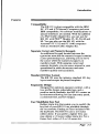
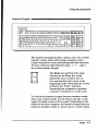
Features
Compatibility
The KB 101 is plug-compatible with the IBM
PC, XT and AT Personal Computers and most
IBM compatibles. No software modifications or
special interfaces are needed. With the addition
of a PS/2 Cable Adapter Kit, you can use the
KB 101 with PS/2™ Models 25, 30, 50,60 and
80. You can also use the KB 101 with the
Amstrad* PC 1512 and PC 1640 computers
with an Amstrad Cable Adapter Kit.
Separate Cursor and Numeric Keypads
An additional keypad located between the
typewriter area and the numeric keypad contains
cursor positioning keys, allowing you to move
the cursor while the numeric keypad is in
numbers mode. With separate cursor and
numeric keypads, you can move around in your
spreadsheet or other documents and enter
numbers quickly and accurately.
Standard 101 Key Layout
The KB 101 uses the industry-standard 101-key
layout and accepts keyboard templates.
Ergonomic Design
Designed for optimum operator comfort, with a
low profile design, adjustable legs, and a
positive tactile feedback, the KB 101 creates an
environment allowing for fast data entry speed,
a consistent feel, and low fatigue.
User Modiflable Key Feel
Rubber dome kits that enable you to modify the
key feel of your KB 101 are available through
the Accessories Catalog or Flyer included with
the keyboard. The KB 101 uses a 2.0 ounce
mbber dome. If you prefer a lighter feel, you
may obtain a 1.0 ounce mbber dome kit. For a
firmer feel, order a 2.5 or 3.0 ounce kit.
Page
1-3
Features
Key Tronic Reliability
The KB 101 is designed for reliability and
durability, using microprocessor electronics and
solid-state capacitive switches rated at 100
million keystrokes each. The keyboard is FCC,
UL and VDE certified.
User's Guide
Overview
This User's Guide provides you with detailed information on how to install and use your keyboard. After the
keyboard is installed and you are familiar with its
operation, keep the User's Guide as a reference for
technical and customer support information.
An overview of the User's Guide is given below.
Section 2, Installation, provides step-by-step instmctions for installing the keyboard and setting
the mode switches.
Section 3, Using the Keyboard, helps you become
familiar with the keyboard layout. Each
major area of the keyboard is described.
Section 4, Keyboard Maintenance, describes how to
clean the keyboard and how to purchase
keyboard enhancement and protection
accessories. This section also describes
how to change the key feel with a Rubber
Dome kit.
Page 1-4
Introduction
User's Guide
Overview
Appendix A, Technical Reference, includes keyboard
interface information, scan code listings,
and a summary of keyboard specifications.
Appendix B, Customer Support Information,
describes how to obtain technical assistance
and how to retum keyboards for repair. The
Key Tronic limited warranty is also listed.
Appendix C, Glossary, contains a list of keyboard and
technical terms.
User's Guide
Conventions
Throughout the User's Guide, initial references to
keyboard and technical terms are indicated in bold, italic
type. These terms are defined in the glossary in Appendix
C.
Page l-S
Section 2
INSTALLATION
Section 2 provides illustrated step-by-step instmctions
for installing the KB 101™ keyboard. This section also
describes how to set the keyboard mode switches.
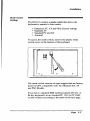
Preliminary
Steps
Ensure that your keyboard box contains the following:
•
•
•
•
KB 101 keyboard
Connecting cord (installed)
User's Guide with Registration Card
Accessories Catalog or Flyer
Notify your dealer immediately if any items are missing
or damaged. See Appendix B for detailed Customer
Support Information.
Please retain the keyboard box for reuse in case you need
to retum your keyboard for service. The foam end caps
are custom designed to protect and secure the keyboard
during shipment.
Please complete the registration card included in this
User's Guide and retum it to Key Tronic. The registration
card enables Key Tronic to keep you informed of product
upgrades and enhancements.
Page 2-1
Keyboard
Installation
The KB 101 keyboard is preset to function with enhanced PC/XT^", AT* and PS/2™ Models. If your
present IBM keyboard has 101 keys it is an enhanced
model. Standard IBM keyboards have 83 or 84 keys.
Installation for IBM computers having enhanced 101
keyboards is simply a matter of plugging the KB 101
keyboard into the computer. However, if you have an
IBM standard model keyboard or an Amstrad computer,
you will need to set the keyboard mode switches before
connecting the keyboard. See Mode Switch Settings later
in this section.
To install the KB 101 keyboard, perform the following
steps:
Step 1.
Page 2-2
Tum OFF your computer before installing
the KB 101 keyboard.
Installation
Keyboard
Installation
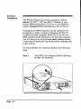
Step 2.
Unplug your existing keyboard and replace
it with your KB 101 keyboard. Insert the 5pin keyboard connector into the keyboard
socket on the rear panel of the system unit.
The IBM PC has two receptacles, labelled
Keyboard and Cassette, and the IBM XT
and AT have a single receptacle as shown
below.
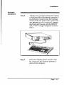
Step 3.
Place the computer power switch to ON.
On power-up, the computer performs a
short self-test program.
Page 2-3
Keyboard
InstaUation
m^a^^i^m^m^^i^^^^^m^^m^^i^^^mi^^^
Upon successful completion of the self-test, the DOS
prompt is displayed and you can begin using the system.
If you receive a keyboard error message or receive
garbled characters on your monitor, check the keyboard
cable connection and make sure the mode switches are
set properly.
If you need additional assistance call our Product
Support Specialists at 1-800-262-6006. In Canada, call
1-800-348-6006.
Page 2-4
Installation
Mode Switch
Settings
The KB 101 contains a mode switch that allows the
keyboard to operate in four modes:
•
•
•
•
Enhanced XT, AT and PS/2 (factory setting)
Standard AT
Standard PC and XT
Amstrad
To access the mode switch, remove the plastic mode
switch cover on the bottom of the keyboard.
The mode switch consists of eight toggles that are factory
preset to OFF, compatible with the enhanced XT, AT
and PS/2 Models.
If you have a standard IBM model keyboard (83-key or
84-key keyboard), or an Amstrad PC 1512 or PC 1640,
set the switches according to the table on the next page.
Page 2-5
Mode Switch
Settings
Enhanced XT/AT
and PS/2 Models
(Factory Setting)
Switch 1
Switch 2
Switches 3-8
OFF
OFF
OFF
Standard AT
Switch 1
Switch 2
Switches 3-8
ON
ON
OFF
Standard PC & XT
Switch 1
Switch 2
Switches 3-8
ON
OFF
OFF
Amstrad
Switch 1
Switch 2
Switches 3-8
OFF
ON
OFF
To change a mode switch setting to ON, simply slide the
appropriate switch towards the side marked "ON". To
change a mode switch to OFF, slide the switch back
towards the "number" or OFF side as shown below.
ON
Page 2-6
Section 3
USING THE KEYBOARD
Section 3 identifies the major areas of the keyboard. A
description of each area is given and the function of each
special, non-character key is explained. Not all programs
use the keys in the same ways. Common functions are
described here.
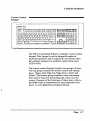
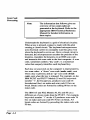
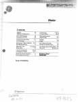
Keyboard
Organization
The KB 101™ keyboard is divided into five areas:
Function Key Area
LED Panel
Numeric Keypad
Cursor Control Keypad
Typewriter Area
llNybMC
rTTTj
H BBPnmi
WWW]
3BQEQ
laHEQHaaHHQGDPEEE BBS
BBgl @BQP
^••••••••••••1:
ggm^mg^
EQQU
KB 101 Keyboard Layout
Each of these areas is described briefly on the following
pages. For additional information on specific key
functions refer to the IBM Guide to Operations for your
particular computer, the IBM DOS Manual, or your
application program manual.
Page 3-1
Function Key
Area
t][".¥]F\
www\
EHsa
BBS SB B p
BBS HIT S
BBB
B
B
ei9EEEEEH^
The KB 101 has twelve multi-purpose/iinc/ion keys, Fl
through F12, located across the top of the keyboard for
easy access. The function of each key is defined by the
application program you are using.
In addititon, the function key area also contains the
Escape (Esc), Print Screen (Print Sem), Scroll Lock and
Pause keys. A brief explanation of each of these keys is
given below.
[I
^
ySy»Hq\,
The function of the Escape (Esc) key
varies among applications. It is often used
to display menus, to exit a function, or to
cancel a command.
The Print Screen (Print Sem) key is a
dual-function key. When this key is
pressed alone, the data displayed on your
monitor is printed.
An Alt-Print Sem combination performs
the System Request (Sys Rq) function.
Page 3-2
Using the Keyboard
Function Key
Area
Note:
Sj
7.
Scroll
Lock
//
\^
The System Request function is
performed only when the keyboard is
configured in AT mode. The System
Request function is defined in your
operating system or application
program manual.
The function of the Scroll Lock key
varies among applications. Typically,
when Scroll Lock is enabled, cursor key
movement causes the text on the screen
to move (scroll) behind the cursor while
the cursor remains stationary. When
Scroll Lock is disabled, the cursor
moves over the text while the text
remains stationary.
When scroll lock is enabled, the Scroll
Lock LED is ON. The Scroll Lock LED
is described on the next page.
/Break \ ,
The Pause key is a dual-function key.
Pressing the Pause key stops screen
listings so that you can read the screen.
Pressing any key will resume the listing.
A Ctrl-Pause combination performs the
Break function. Break typically is used
to cancel the current operation and
terminate the program.
Page 3-3
LED Panel
I h ^ t n W c 'iicH I
BBS SBB
gSB
E^BBBBBBBBBBBBO BBS BBB
BBBBBB
The Num Lock, Caps Lock, and ScroU Lock LEDs are
grouped together, making it easy to see if a key function.
Caps Lock, for example, is active. The corresponding
LED status indicator is activated when you press the
Num Lock, Caps Lock or Scroll Lock key. When an LED
is illuminated, the function is enabled.
When the particular function is no longer desired, press
the key. The function is disabled, and the LED is
extinguished.
Note:
Page 3-4
The status of the Num Lock LED at
power-up varies with the model of the
host computer. The Caps Lock and Scroll
Lock functions are disabled at power-up,
and their LEDs are OFP.
Using the Keyboard
Numeric Keypad
www\
B IBBBBI FFFF1
BBS
E3BBBBBBBBBBBBO BBS
The numeric keypad provides a quick, easy way to enter
numeric values while still having a separate cursor
control keypad for cursor positioning and edit functions.
All four common math function signs: /, *, - and -i-,
are on the numeric keypad.
\^z^
The Enter key performs the same
function as the Enter key in the
typewriter area. It ends a line of
text and positions the cursor at the
beginning of the following line. It also
performs the "Enter" function,
instmcting the computer to perform
a specific command or to start a job.
To switch the numeric keypad between numbers mode
and cursor control mode, use the Num Lock key in the
upper left-hand comer of the keypad. Depending on the
model of the host computer, the numeric keypad may be
placed in numbers mode on power-up or a system reset.
Page 3-5
Numeric Keypad
The Num Lock LED indicates whether the keypad is in
numbers mode (LED is ON) or in cursor control mode
(LED is OFF).
The grey keys: /, *, -, + and Enter, are active in
numbers mode. In most programs, they remain active
even when Num Lock is OFF (keypad in cursor control
mode).
Note:
When the Num Lock LED is OFF and the
numeric keypad is in cursor control mode,
numbers can still be entered by pressing the
Shift key with the desired nuniber.
Also, most programs allow you to use the
cursor keys while the numeric keypad is in
numbers mode, by pressing Shift with the
desired key.
When the numeric keypad is in cursor control mode, it
performs the cursor movement, document control, and
editing functions marked on the keycaps.
Page 3-6
Using the Keyboard
Cursor Control
Keypad
n^hSTTTTTI
Q IBBBBI IBBBBI
WWW]
^BS SB
BBBBBBBBBBBBBE BOS
SBBBBBBBBBBBBO
BHEEEESa^
BB
IB
The KB 101 keyboard features a separate cursor control
keypad. This keypad is active during all modes of
keyboard operation and is especially convenient when
the numeric keypad is in numbers mode (Num Lock
LED is ON).
The cursor control keypad contains two groups of keys.
The top group contains document control and editing
keys: Home, End, Page Up, Page Down, Insert and
Delete. The bottom group contains cursor movement
keys (arrow keys) for positioning the cursor on your
screen. If unsure of the functions of these keys, refer to
the IBM Guide to Operations for your particular computer, or your application program manual.
Page 3-7
Typewriter
Area
I h^ tme . 1*771
H IBBBBMBBBBIIBBBB
BBS SBB
E§QBBBBBBBBBBBO BBS
BBB
ETE
The typewriter area conforms to the industry standard 101
key layout and has an Alt key and Ctrl key on each side of
the space bar.
All the white keys in the typewriter area are "typematic";
repeating as long as you hold them down.
Note'.
Page 3-8
If you are used to typing on a typewriter,
you may have used a lowercase letter "1" or
uppercase letter "I" for the number one.
Similarly, you may have used an uppercase
letter "O" for the number zero. Because the
keyboard sends unique scan codes for each
key on the keyboard, the above substitutions
can create unpredictable results. Always use
numeric keys for one and zero.
Using the Keyboard
Typewriter
Area
The non-character keys located in the typewriter area are
described below.
^
The Backspace key is used to delete
characters. Pressing Backspace
moves the cursor one position to the left,
removing that character. The function of
the Backspace key may vary slightly,
depending on the software you are using.
^
The Enter key normally works like a
carriage retum, moving the cursor to the
start of a new line. The key also performs
"Enter" functions, instmcting the computer to perfonn a specific command or
start a job.
4-J Enter
l£
^
Shift
\
\L
\f
^
Note:
Use either of the two Shift keys to enter
uppercase letters or to enter the symbol or
character shown in the upper position on
the keycap. In most application programs,
a Shift key may be used together with the
numeric keys to enter numbers when the
numeric keypad is in cursor control
mode.
The Control (Ctrl) key is used with
another key or key combination to
perform a command or function. Instmctions may be passed to WordStar® files,
for example, through Ctrl-key combinations.
To activate a Ctrl-key command, press
and hold down the Ctrl key first and
then press the second key.
Page 3-9
Typewriter
Area
7\
V—^
Capi.
Lock
}
\
The Alternate (Alt) key can be used in
combination with other keys to obtain
different characters or key functions. For
example, you can use Alt with certain
letter keys to enter BASIC statement
keywords quickly. Some application
programs use Alt-key combinations.
Lotus 1-2-3® uses the Alt key to trigger
macro commands.
The Caps Lock key enables and disables
the capital letters function. The Caps
Lock LED in the LED control panel
indicates whether the Caps Lock function
is active or inactive.
The Caps Lock function only affects the
letter keys. Use a Shift key to type a
symbol shown on the upper portion of
other keys.
\L
Page 3-10
^
The Tab key moves the cursor to the
right, to the next tab stop. In some
applications, such as DOS, a Shift-Tab
moves the cursor left, to the previous tab
setting.
Using the Keyboard
Keyboard
Height
Adjustment
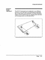
The KB 101 keyboard can be adjusted to two different
positions, level and tilted, by positioning the adjustable
legs on the bottom of the keyboard. To tilt the keyboard,
simply lift the keyboard legs up, snapping them into their
self-locking position as illustrated below.
Page 3-11
Section 4
KEYBOARD MAINTENANCE
Section 4 describes how to clean the KB 101™ keyboard
and how to purchase keyboard protection accessories.
Cleaning the
Keyboard
The KB 101 keyboard is designed and manufactured to
operate without preventive maintenance. However, you
may want to clean the keyboard exterior periodically.
Use a mild, household-type cleaner and a soft, damp,
lint-free cloth or paper towel.
To prevent spray cleaner from mnning into the keyboard,
spray the cleaning solution onto a cloth or paper towel.
Avoid spraying directly onto the keyboard. Be careful
not to wipe dirt into the keyboard.
Note:
Keyboard
Protection
Accessories
Do not use a petroleum-based solvent, as
this will damage the plastic keyboard
enclosure and painted surfaces.
Keyboard protection items such as dust covers, antistatic mats, and mini vacs, can be purchased through the
Accessories Catalog or Flyer included in the keyboard
shipping box. The catalog or flyer contains order forms
and information on a number of accessories to enhance
and protect your keyboard.
Page 4-1
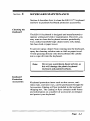
Modifying the
Key Feel
While Key Tronic prides itself on its keyswitch technology that provides a consistent, positive tactile response,
some users may prefer the key feel or touch to be slightly
firmer or lighter.
Key Tronic offers a "Rubber Dome Kit" allowing you to
modify the key feel by changing the mbber domes in
your keyboard. (Rubber domes are located underneath
the keycaps and control the responsiveness of a key.)
Your KB 101 keyboard is equipped with 2.0-ounce
mbber domes from the factory, but can be changed to
1.0, 2.5 or 3.0-ounce mbber domes.
The 1.0-ounce mbber dome kit provides a lighter feel,
and the 2.5 or 3.0-ounce kits provide a firmer feel. The
kit includes enough mbber domes (75) to modify the feel
for all the white keys on the keyboard (with the exception
of the space bar), a keycap removal tool and installation
instmctions.
Refer to the Accessories brochure for ordering and
pricing information.
Page 4-2
Appendix A
TECHNICAL INFORMATION
The Technical Information Appendix includes the
following information:
• Keyboard interface information describing the
5-pin DIN connector.
• Overview of how scan codes are processed.
• IBM PC/XT™ and AT* scan code charts.
• Specifications for the KB 101 keyboard.
Keyboard
Interface
Information
Communications between the keyboard and host
computer occur through a shielded keyboard cable. The
cable end has a 5-pin DIN connector that attaches to the
receptacle located on the rear panel of the computer.
The cable contains a logic ground line, power line, and
bi-directional clock and data lines. Data I/O uses
synchronous, serial protocol.
An illustration of the 5-pin DIN connector and a table
showing the function and signal or voltage of each pin is
shown below.
Pin
Function
1
2
3
4
5
Clock
Data
Not used
Ground
Power
Signal/
Voltage
TTL
TTL
OVdc
-1-5 Vdc
Keyboard
Connector
x - ^
1[•
•)3
Kj^.
2
5-pin DIN
Connector
Page A-1
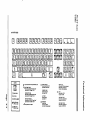
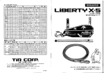
Scan Code
Processing
Note:
The infonnation that follows gives an
overview of how scan codes are
generated at the keyboard. Refer to the
^propriate IBM Technical Reference
Manual for detailed information on
these topics.
Undemeath the keyboard is a grid of electrical circuitry.
When a key is pressed, contact is made with the grid,
creating a closed circuit. The keyboard microprocessor
uses electrical current to constantly scan this grid, even
when the keyboard is not in use. Once a closed circuit is
detected, the microprocessor encodes the position of the
keypress, translates the keypress to an IBM scan code,
and transmits this scan code to the host computer. A scan
code, sometimes called a "key code", is a numerical
value that uniquely identifies each keyboard key.
Each key or keyswitch on the computer is represented by
two scan codes: a "down" scan code (make code), sent
when a key is pressed, and an "up" scan code {break
code), sent when the key is released. For example, on the
IBM PC/XT and PS/2™ Models 25 and 30, keyswitch
number "1", the Escape key, produces scan code 01
hexadecimal (hex) on make and scan code 81 hex on
break. Break codes are formed by adding 80 hex to the
make code.
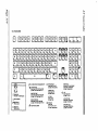
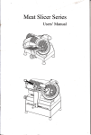
The IBM AT and PS/2 Models 50,60, and 80 use a
different set of scan codes than the PC/XT. For example,
keyswitch number "1" on the AT produces scan code 76
hex on make and scan code FO 76 hex on break. AT
break codes are formed by preceding the make code with
FO hex.
Page A-2
I" ^
a
a
101 pcnrr CODES
I
3C I I
3B||
3D I I
a
3E|
|. B B | | . B C | | . B D | | . B E |
I 29 I I 0 2 | | 0 3 | | 0 4 | | 051 | 06 j l
42
, P2
43
„C3
44
„C4
57
..D7
0711 081 I 09 11 OAl I OBl | OCll GDI
<B
OE
8E
l„*»M,.«l|..M|Ua||„iS||„ii||„i7||„w||„S9||„iA||„Sg||,i£||J5|
8F 11.80 I L »^ ll». ^^ I M3 |l«^ I l-°H l«^° I 1-^^ 11- «° I L ^ I U * I I»9B||..
3A
. BA
„
1E
,9E
2A
AA
1F
.,9F
20
„AC
1D
9D
33
«B8
20
„A0
2D
„AD
21
„A1
22
„A2
23
24
„ A3 „ A4
25
„ A5
2E
26
„ A6
33
,.83
27
„ A7
34
MB4
39
B9
Up C o d * and Down C o d * p r « c * * d * d by EO
I
[ E UP CODE
Q
r
SWTTCH NUMBER
<T|
MULTIPLE KEY
SPECIAL CASE
Key* without auto rvpsat
»
,iC7
UC9
53^
nD3
' 4F^
uCF
51
»D1
36
B6
PRINT SCRN KEY
Down Code: EO 2A EO 37
Up C o d * : E 0 B 7 E 0 A A
£8
9D
50
«D0
45 1 <T1
^C5
J ^
47
ALT CASE
Down Code: 54
Up Code: D4
<T]
PAUSE KEY
Down Coda:
E1 1 D 4 5 E 1 0 O C 5
Up Code: None ge rte rated.
1 37
|^B7
1 48 1
„C7 ^ c e
1 4C 1 4D
„CC „CD
4F
.CF
50
„D0
,„
52
D2
BREAK CASE
Active only it Ctrl key l i p r e i s e d .
Down Code: E0 4 6 E 0 C 6
Up Code: Nonegerterated.
LEFT SHIFT CASE
Down C o d * : EO AA EO 35
Up C o d * : E 0 B 5 E D 2 A
RIGHT SHIFT CASE
Down Cods: E 0 B 6 E 0 35
Up C o d * : E 0 B 5 E 0 36
4A
49
„C9
4B
„CB
CONTROL CASE
Down C o d * : EO 37
Up C o d * : E 0 B 7
niGHT SHIFT CASE
Down C o d * : EO BG EO " D o w n C o d * "
Up C o d * : E 0 " U p C o d * - E 0 3e
NUM LOCK ON CASE
Down Code: EO 2A EO ~Down Code"
Up Coda: EO "Up C o d e " EO A A
1."
„
11D2
1C
9C
1^38
» B8
LEFT SHIFT CASE
Down Code: EO AA EO ~Down Code"
Up C o d * : EO "Up C o d * " EO 2A
Q ] DOWN CODE
28
^A8
<J1
51
„D1
1 53
|,.,D3
4E
CE
»
r—
IC
9C
on
S
a
n
I.
101 AT SCAN CODES
BBS
0 0 0 BSHE
HBBHBBBBEESHBCEl 0 0 0 B B B
IBBBBBBBBBBCZE]
BBB
IBBBBBBBBBCZZ] 0 B B B
H HC
]H E 000
1."
OE
1 OS
06
04 11 OC
L_ i . '
16
•
1 IE
1.
.
'm"'
a i
DOWNC ODE
UP COC E: FO'TMWH CODE-t
[7] SWITCH NUMBER
W
^
MULTIPLE KEY
SPECIAL CASE
03
•
OB
'
1 83
,
01
46
.r
Up C o d * m d Down Code p r * c * * d * d by EO
45
09
78
07
1 4E
55
66
ALT CASE
Down Code: 64
Up Code: FO 84
O
BREAK CASE
Active only If Ctrl key l i p r * t s * d .
Down C o d * : E0 7 E E D F O 7 E
Up C o d * : N o n e g e n * f « t « d .
PRINT SCAN KEV
Down C o d * : E0 12E0 7C
Up C o d * : EOF0 7 C E O F 0 1 2
CONTROL CASE
Down C o d * : E0 7C
Up C o d * : E 0 F 0 7C
RIGHT SHIFT CASE
Down C o d * : EO FO Sfi EO " D o w n C o d * "
Up Cod*-. EO FO " D o w n C o d * " EQ »
HUM LOCK ON CASE
Down C o d * : EO 12 EO " D o w n C o d * "
Up C o d * : EO FO "Down C o d * " EO FO 12
I.
<T]
LEFT SHIFT CASE
Down C o d * : EO FO 12 EO " D o w n Coda"
Up C o d * : E O F O - D o w n C o d * " E D 1 2
K«v* wttlTCut auto r»p*at
< r n SINGLE KEY
SPEOAL CASE
OA
li_ •
26 1 1 25 1 2E
36
3D 1 3E
11..
"
.1
»
i»
.
LEGEND
Q
JL_
PAUSE KEY
Down C o d * :
E l 14 77 E l F0 14 FO 77
Up Coda: N o n * Qanarat*d.
O
/KEY
Down C o d * : EO 4A
Up C o d * : E 0 F 0 4A
LEFT SHIFT CASE
Down C o d * : E 0 F 0 1 2 E 0 4 A
Up C o d * : E 0 F 0 4 A E 0 1 2
RKiHT SHIFT CASE
Down Coda-. E 0 F Q 5 9 E O 4 A
Up Code: EOF0 4 A E 0 9g
Technical Information
Keyboard
Specifications
The KB 101 keyboard has the following specifications:
Electrical Data:
Max. input power
Rollover
Serial data output
Mechanical Data:
Key total travel
Key activating force
Key color
Enclosure color
Switch reliability
Mode Switch Settings:
Enhanced XT/AT, PS/2
Standard AT
Standard PC and XT
Amstrad
Environmental Data:
Operating temp.
Non-operating temp.
Relative humidity
Altitude
350 mA max. @ -i-5 Vdc
N-key rollover (NKRO)
Synchronous 8-bit data
0.150 in. (3.81 mm)
2.0 oz. (55 grams)
Fog (ABS 2500)
Sea Mist (ABS 20779)
Driftwood (ABS 22061)
100 million MCBF
1
Off
On
On
Off
2
Off
On
Off
On
3-8
Off
Off
Off
Off
0 to 55 degrees C
-40 to 70 degrees C
20% to 95%
-1,000 ft. to-1-12,000 ft.
Page A-S
Appendix B
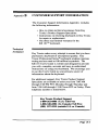
CUSTOMER SUPPORT INFORMATION
The Customer Support Information Appendix includes
the following information:
• How to obtain technical assistance from Key
Tronic's Product Support Specialists.
• Instmctions on retuming keyboards to Key Tronic
for repair or replacement.
• The three-year limited warranty for the
KB 101™ keyboard.
Technical
Assistance
Key Tronic makes every attempt to ensure that you have
purchased a keyboard of unsurpassed quality. Key
Tronic Professional Series* keyboards undergo rigorous
testing and are rated at 100 million keystrokes. The
KB 101 User's Guide is written and designed to provide
you with complete, accurate and easy-to-understand
instmctions on using your keyboard. We encourage you
to use this User's Guide as your primary source of
information about the keyboard.
For additional support. Key Tronic Product Support
Specialists are available to assist you from 7:(X) AM
through 3:(X) PM PST, Monday through Thursday and
from 7:00 AM through 12:00 Noon PST on Friday. Their
telephone number is listed below.
Key Tronic Product Support
1-800-262-6006 (U.S.) Toll Free
1-800-348-6006 (In Canada) Toll Free
(509) 927-5515 (outside U.S. or Canada)
Page B-1
Technical
Assistance
European customers who need technical assistance or
encounter keyboard problems should contact an authorized Key Tronic Distributor. The dealer you purchased
your keyboard from can provide you with the name and
address of the Key Tronic Distributor nearest you.
Your Key Tronic Distributor will contact a Customer
Service Representative from Key Tronic Europe who will
determine whether a keyboard has to be retumed to Key
Tronic for repair. Upon authorization of retum, your
distributor will give you shipping instmctions.
Canadian Customer Support
Canadian customers needing keyboard service or
repair should contact our KT Services office in
Toronto. They can be reached at (416) 446-1669.
Page B-2
Customer Support Information
Return for
Repair
Procedure
If a keyboard proves to be defective you may retum it to
Key Tronic for repair. To qualify for "in-warranty
repair", proof-of-date-of-purchase must be included with
the retumed keyboard.
Before retuming the keyboard, contact Key Tronic
Product Support to make sure that the problem cannot be
solved over the telephone.
The following steps explain the procedures for retuming
your keyboard:
Step 1.
Call Key Tronic Product Support for a
Retum Authorization (RA) number.
At that time, the Product Support Specialist
will obtain your name, address and phone
number, the keyboard model and serial
number, and a description of the problem.
The address of the nearest repair center will
be given to you.
Step 2.
Carefully pack the keyboard in its original
shipping container if possible. If the original
container is not available, wrap the keyboard in non-static material such as newspaper and pack it in a sturdy cardboard box.
Please be sure the RA number is visible on
the outside of the box on the shipping label.
Note:
To qualify for "in-warranty" repair service
on your keyboard, a copy of the sales
receipt or invoice showing the date
purchased must accompany the keyboard.
Page B-3
Retum for
Repair
Procedure
Step 3.
Keyboards retumed to Key Tronic for repair
must be shipped prepaid. It is recommended
that the keyboard be insured when shipped.
Note:
Key Tronic will not accept units without a
Retum Authorization Number posted on the
outside of the shipping carton.
For keyboards that are repaired under warranty, they will
be shipped back to you by prepaid UPS or equivalent
service.
For "out of warranty" keyboards, follow the steps listed
above. Repairs will be made at your expense. Normal
tum-around is 10 working days on prepaid retums,
subject to availability of parts. Keyboards will be
retumed to you at your expense by UPS or equivalent
service unless otherwise specified or requested.
Page B-4
Customer Support Information
Limited
Warranty
Key Tronic Corporation warrants the products which it
manufactures to be free from defects in materials and
workmanship for a period of three (3) years from the date
of purchase from Key Tronic or an authorized Key
Tronic dealer. This warranty is limited to such purchaser
and is not transferable.
During the three (3) year warranty period. Key Tronic
will repair or replace, at its option, any defective
products or parts at no additional charge, provided that
the product is retumed, shipping prepaid, to Key Tronic,
an authorized dealer or an authorized service location.
The purchaser is responsible for insuring any retumed
product and assumes the risk of loss during shipping. All
replaced parts and products become the property of Key
Tronic.
Proof-of-purchase showing the date of purchase must be
provided by the purchaser when requesting that warranty
work be performed. The purchaser may request information on how to obtain warranty service by contacting an
authorized dealer or writing to Key Tronic, P.O. Box
14687, Spokane, WA, 99214, U.S.A. or by calling 1-800262-6006, or, in Canada, 1-800-348-6006. If calling
from outside the continental U.S.A. or Canada, call
Spokane, Washington, U.S.A., (509) 927-5515.
This limited warranty does not extend to any products
which have been damaged as a result of accident, misuse,
abuse, or as a result of service or modification by anyone
other than Key Tronic, an authorized dealer or an
authorized service location. This limited warranty does
not extend to the use of this product with any equipment
other than the equipment for which it is designed.
Page B-5
Limited
Warranty
EXCEPT AS EXPRESSLY SET FORTH ABOVE, NO
OTHER WARRANTIES ARE EXPRESSED OR
IMPLIED, INCLUDING, BUT NOT LIMITED TO,
ANY IMPLIED WARRANTIES OR MERCHANTABILITY OR HTNESS FOR A PARTICULAR PURPOSE. KEY TRONIC EXPRESSLY DISCLAIMS ALL
EXPRESSED OR IMPLIED WARRANTIES NOT
STATED HEREIN. IN THE EVENT THE PRODUCT
IS NOT FREE FROM DEFECTS AS WARRANTED
ABOVE, THE PURCHASER'S SOLE REMEDY
SHALL BE REPAIR OR REPLACEMENT AS PROVIDED ABOVE. UNDER NO CIRCUMSTANCES
WILL KEY TRONIC BE LIABLE TO THE PURCHASER OR ANY USER FOR ANY DAMAGES,
INCLUDING ANY INCIDENTAL OR CONSEQUENTIAL DAMAGES, EXPENSES, LOST PROHTS,
LOST SAVINGS, OR OTHER DAMAGES ARISING
OUT OF THE USE OF, OR INABILITY TO USE, THE
PRODUCT.
Some states do not allow the exclusion or limitation of
incidental or consequential damages for consumer
products, and some states do not allow limitations on
how long an implied warranty lasts, so the above
limitations or exclusions may not apply to you.
This limited warranty gives you specific legal rights, and
you may also have other rights which vary from state to
state.
Page B-6
Appendix C
GLOSSARY
This glossary defines a number of keyboard and technical
terms used throughout this User's Guide.
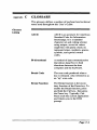
Glossary
Listing
ASCII
ASCII is an acronym for American
Standard Code for Information
Interchange. It is a standard
character set and coding scheme
using unique, seven-bit values
(eight bits with parity check) to
represent letters, numbers, spaces,
symbols, and special control
codes.
Bi-directional
A method of data communication
that allows data flow in both
directions between the host
computer and the keyboard.
Break Code
The scan code produced when a
key is released. Also referred to as
an "up" scan code.
Break Function
The Break function is the secondary function of the Pause key. To
enable the Break function, press
and hold the Ctrl key, then press
the Pause key. Typically, CtrlPause ends the current application
and retums you to the DOS
prompt.
Page C-1
Glossary
Listing
Page C-2
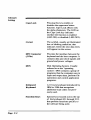
Caps Lock
Pressing this key enables or
disables the uppercase letters
function. Caps Lock affects only
the alpha characters. The LED on
the Caps Lock key indicates
whether the function is enabled
(LED ON) or disabled (LED OFF).
Cursor
The symbol, usually an illuminated
txjx or blinking underline, that
indicates where the next data entry
will appear on the screen.
DIN Connector
(5-Pin)
Provides the interface between the
keyboard and the host computer. It
contains data and clock signals and
ground and power voltages.
DOS
Disk Operating System. Usually
referred to as the "operating
system". DOS contains a group of
programs that the computer uses to
input and output data, perform file
operations emd control application
programs.
Enhanced
Keyboard
A 101-key keyboard introduced by
IBM in 1986 that recognizes
additional scan codes not previously used.
Function Keys
Special keys located across the top
of the keyboard (Fl through F12)
that perform functions specific to
the software being used.
Glossary
Glossary
Listing
Host Computer
The computer to which the
keyboard is connected. This could
be an IBM PC™, XT™, AT*,
PS/2™, or an Amstrad™ PC 1512
or PC 1640.
Keyboard
Interface
The KB 101™ keyboard uses a
5-pin DIN connector to connect
to the host computer. This
connection carries the signals
necessary for the keyboard and
host computer to communicate.
LED
Light Emitting Diode. The KB
101 keyboard contains three LEDs
that are used to show the status of
the Num Lock, Caps Lock and
Scroll Lock keys. Each LED
illuminates when the function is
active.
Make Code
The scan code produced when a
key is pressed. Also referred to as
a "down" scan code.
Mode Switch
The mode switch consists of eight
ON/OFF toggles housed within
the keyboard. Different switch
settings allow the KB 101 keyboard to be compatible with the
IBM PC, XT, AT and PS/2
Models, and the Amstrad PC 1512
and PC 1640 computers.
Page C-3
Glossary
Listing
Page C-4
Num Lock
Pressing this key enables or disables the numeric keypad. When the
numeric keypad is enabled, the LED
on the Num Lock key is ON and the
keypad is used to enter numbers.
When numeric mode is disabled, the
LED on the Num Lock key is OFF
and the keypad is placed into cursor
control mode.
Prompt
The symbol displayed on the screen
that indicates the computer is ready
to receive an instmction.
RA Number
Retum Authorization Number.
You must obtain this number from
Key Tronic Customer Support
before retuming a keyboard for
repair.
Reset
The process of restarting the host
computer when the computer is
already on, by pressing the CtrlAlt-Del keys simultaneously. Also
called a "warm boot".
Scan Code
A numerical value that uniquely
identifies each key on the keyboard.
Each key is represented by a
"down" scan code, generated when
the key is pressed, and a corresponding "up" scan code, generated
when the key is released.
Glossary
Glossary
Listing
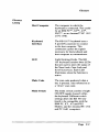
Scroll Lock
Scrolling
Pressing this key enables or
disables the Scroll Lock function.
When Scroll Lock is active, the
Scroll Lock LED is ON.
To move data on the screen up
or down, so that parts of the
document outside the screen area,
or window, move into view.
Serial Data
Data that is transmitted in
sequence, one bit at a time, rather
than an entire byte (group of bits)
at a time.
Standard
Keyboard
An 83-key keyboard introduced by
IBM in 1981 for the IBM PC or an
84-key keyboard for the IBM AT.
Synchronous
A method of data communication
in which a group of characters is
sent as a continuous stream of bits.
The characters, data bits, are sent
at a fixed rate, with the transmitter
and receiver synchronized (clock
controlled). This eliminates the
need for start and stop bits.
Page C-5