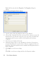
1
Dell™ Remote Console Switch
Software User's Guide
Notes
NOTE: A NOTE indicates important information that helps you make
better use of your computer.
Third Party Software. You acknowledge that the SOFTWARE PRODUCT may
contain or be provided with copyrighted software of Dell's suppliers as identified in
associated documentation or other printed or electronic materials (“Third Party
Software”) which are obtained under a license from such suppliers. Your use of any
such Third Party Software shall be subject to and you agree to comply with the
applicable restrictions and other terms and conditions set forth in such documentation
or materials as set forth in any “Third-Party Licenses ReadMe” file or similar file
located in the installation directory for the SOFTWARE PRODUCT.
Any open source software is distributed in the hope that it will be useful, but is
provided “as is” without any expressed or implied warranty; including but not limited
to the implied warranty of merchantability or fitness for a particular purpose. In no
event shall Dell, the copyright holders, or the contributors be liable for any direct,
indirect, incidental, special, exemplary, or consequential damages (including, but not
limited to, procurement of substitute goods or services; loss of use, data or profits; or
business interruption) however caused and on any theory of liability, whether in
contract, strict liability, or tort (including negligence or otherwise) arising in any way
out of the use of this software, even if advised of the possibility of such damage.
Reproduction of these materials in any manner whatsoever without the written
permission of Dell Inc. is strictly forbidden.
Trademarks used in this text: Dell, the DELL logo, and OpenManage are trademarks
of Dell Inc.; Intel Pentium is a registered trademark of Intel Corporation in the U.S.
and other countries; Microsoft, Windows, and Windows Vista are either trademarks or
registered trademarks of Microsoft Corporation in the United States and/or other
countries; Avocent is a registered trademark of Avocent Corporation or its affiliates
in the US and other countries; Red Hat and Red Hat Enterprise Linux are registered
trademarks of Red Hat, Inc. in the United States and other countries; SUSE is a
registered trademark of Novell, Inc., in the United States and other countries;
VMware is a registered trademark or trademark (the “Marks”) of VMware, Inc. in
the United States and/or other jurisdictions. Other trademarks and trade names may
be used in this publication to refer to either the entities claiming the marks and names
or their products. Dell Inc. disclaims any proprietary interest in trademarks and trade
names other than its own.
590-1022-501B
Remote Console Switch
August 2011
Contents
Product Overview
7
Features and Benefits
Powerful Customization Capabilities
Extensive Remote Console Switch Management
Authentication and Authorization
7
7
8
8
System Components
RCS Explorer Window
Video Viewer
Interoperability with Avocent® Products
9
9
9
10
Operating Features
Target Device Naming
Target Device Name Displays
Sorting
IPv4 and IPv6 Network Address Capabilities
10
11
11
12
12
Installation
13
Supplied with the Software
13
Supported Operating Systems
13
Hardware Configuration Requirements
14
Supported Browsers
15
JRE Requirements
15
Installing the Software
15
Uninstalling the Software
16
Starting the Software
17
Contentsxxx | xxx3
Configuring Switches and Target Devices
18
Web Interface Installation and Setup
20
Basic Software Operation
23
Viewing Your System in the Explorer
23
Customizing the Window Display
25
Adding a Remote Console Switch (Dell or Avocent)
26
Accessing Your Remote Console Switch
35
Launching the VNC or RDP Viewer
37
Changing Server and Switch Properties
General Properties
Server Network Properties
Switch Network Properties
Information Properties
Server Connections Properties
VNC Properties
RDP Properties
Accessing a Server via a Browser Window
37
37
39
39
40
41
42
43
45
Changing Server and Switch Options
General Options
Default Browser
Changing DirectDraw Support (Windows OS Only)
HTTP/HTTPS Options
VNC Options
RDP Options
45
45
46
47
48
48
49
Organizing Your System
Modifying Custom Field Names
Creating Folders
Assigning a Unit to a Site, Location, or Folder
Deleting and Renaming
50
51
52
53
54
Contentsxxx | xxx4
Customizing the Explorer Window
Modifying the Selected View on Startup
Changing the Default Browser
55
56
56
Managing Your Local Databases
Saving a Database
Loading a Database
Exporting a Database
57
57
58
58
Using the Viewer
61
Accessing Servers from the RCS Software
61
Interacting With the Server Being Viewed
Viewer Window Features
Adjusting the Viewer
Adjusting the Viewer Resolution
Adjusting the Video Quality
Minimizing Remote Video Session Discoloration
Improving Screen Background Color Display
Setting Mouse Scaling
Minimizing Mouse Trailing
Improving Mouse Performance
Reducing Mouse Cursor Flickering
Viewing Multiple Servers Using the Scan Mode
Scanning Your Servers
Thumbnail View Status Indicators
Navigating the Thumbnail Viewer
Using Macros to Send Keystrokes to the Server
Session Options - General Tab
Screen Capturing
63
64
66
69
70
73
74
75
75
76
76
77
77
79
80
81
83
84
Session Sharing Options
Automatic Sharing
Exclusive Mode
Stealth Connection
Preemption Mode
85
85
88
89
91
Virtual Media
94
Contentsxxx | xxx5
Sharing and Preemption
Launching Virtual Media
Mapping Virtual Media Drives
Virtual Media Connection Status
Virtual Media Sessions
95
96
96
98
98
Appendix A: Updating RCS Software
103
Appendix B: Keyboard and Mouse
105
Appendix C: TCP Ports
109
Appendix D: Technical Support
111
Contentsxxx | xxx6
1
Product Overview
The Dell™ Remote Console Switch (RCS) software is a cross-platform
management application that allows you to view and control the switches and all
attached servers. The cross-platform design ensures compatibility with most
popular operating systems and hardware platforms. The RCS software provides
secure switch-based authentication, data transfers, and username/password
storage. Each switch handles authentication and access control individually for
more decentralized system control.
The RCS software utilizes Explorer-like navigation with an intuitive split-screen
interface, providing you with a single point of access for your entire system.
From here, you can manage your existing switches, install a new switch, or
launch a video session to a system server. Built-in groupings such as Servers,
Sites, and Folders provide an easy way to select the units to view. Powerful
search and sort capabilities allow you to easily find any unit.
Features and Benefits
The RCS software is designed for easy installation and operation. Auto-discovery
of managed switches enables you to install new units in minutes. Wizard-based
installation and online help simplify initial system configuration. The intuitive
graphical interface makes managing and updating switches simple and
straightforward.
Powerful Customization Capabilities
You can tailor the RCS software to fit your specific system needs. Take
advantage of built-in groups or create your own. Customize unit and field names
Product Overviewxxx | xxx7
and icons for maximum flexibility and convenience. Using names that are
meaningful to you makes it easy to quickly find any system unit.
Extensive Remote Console Switch Management
The RCS software allows you to add and manage multiple switches in one
system. Once a new switch is installed, you can configure switch parameters,
control and preempt user video sessions, and execute numerous control
functions, such as rebooting and upgrading your switch. The RCS software is
designed to be compatible with the Dell OpenManage™ IT Assistant Event
Viewer, allowing system administrators to consolidate system event reports. You
can enable Simple Network Management Protocol (SNMP) traps, configure
target devices, and manage user databases.
You can use the software to manage the following Dell switches:
•
4322DS
•
2162DS
•
1082DS
•
2161DS
•
2321DS
•
4161DS
•
2161DS-2
•
1081AD
•
2161AD
NOTE: For Dell 1081AD and 2161AD switches, the Dell Remote Access Key (RAK) is
required for the switches to be added/managed through the RCS.
Authentication and Authorization
The RCS software allows permissions for multiple Remote Console Switches to
be managed through a single interface rather than individually on each Remote
Console Switch. For increased security and efficiency, the Lightweight Directory
8xxx | Product Overviewxxx
Access Protocol (LDAP) feature eliminates the need to update access
permissions in individual Remote Console Switches by drawing permissions
from a single network-wide authentication source.
The Remote Console Switch can authenticate using the standard Active
Directory schema, or the Dell Extended Schema in order to maximize
compatibility with all of your Dell hardware.
NOTE: Dell 1081AD and 2161AD switches do not support LDAP.
System Components
The software contains the following major components.
RCS Explorer Window
The RCS Explorer window is the primary point of control for accessing the
software features and functionality. From the Explorer window, you can view the
switches and target devices defined in the local database. Built-in groupings such
as Appliances and Devices provide different ways to list units. You can create
custom groups of units by adding and naming folders. Other groupings are also
available, based on custom fields that you can assign to units.
From the Explorer Devices list, you can select a device from the list of target
devices and start a KVM session with the device. Starting a keyboard, video, and
mouse (KVM) session brings up a Video Viewer. From the Explorer Appliances
list, you can select a switch to configure.
Video Viewer
Users access and manage target devices through the Video Viewer. You can use
predefined macros and choose which macro group is displayed on the Video
Viewer Macros menu. You can open the Video Viewer to connect to target
devices on the Remote Console Switch. For more information, see "Using the
Viewer" on page 61.
Product Overviewxxx | xxx9
The Video Viewer also provides access to the Virtual Media window. You can
use the Virtual Media window to map a physical drive such as a disk, CD-ROM,
or DVD-ROM data drive, onto a target device so that the media device is
available to the target device even though it is not directly connected. For more
information on the Virtual Media window, see "Using the Viewer" on page 61.
Interoperability with Avocent® Products
The RCS software can be used to access some Avocent switches. You can also
manage those Avocent switches, allowing increased flexibility in the
management of systems.
In addition, the RCS software includes support for Avocent IQ modules,
expanding the range of server types that can be accessed/managed. The addition
of support for Avocent IQ modules means that the following connections are
now supported:
•
PS/2 modules (Dell and Avocent modules available)
•
USB modules, including Virtual Media and Smart Card/Common
Access Card (CAC) versions (Dell and Avocent modules available)
•
VT100 Serial modules (Avocent modules available)
•
True Serial modules (Dell and Avocent modules available)
•
Sun modules (Avocent modules available)
•
PS2M modules (Avocent modules available)
NOTE: Dell SIP modules are supported on directly connected Avocent switches.
NOTE: Dell 1081AD and 2161AD switches do not support true serial modules.
Operating Features
The RCS software features include target device naming, target device name
displays, sorting, and IPv4 and IPv6 network address capabilities. "Keyboard and
Mouse" on page 105 lists the Explorer navigation shortcuts. Other components
also support full keyboard navigation in addition to mouse operations.
10xxx | Product Overviewxxx
Target Device Naming
The software requires that each switch and target device have a unique name.
To minimize the need for operator intervention, the software uses the following
procedure to generate a unique name for a target device whose current name
conflicts with another name in the database.
During background operations (such as an automated operation that adds or
modifies a name or connection), if a name conflict occurs, the conflicting name
is automatically made unique. This is done by appending a tilde (~) followed by
an optional set of digits. The digits are added in cases where adding the tilde
alone does not make the name unique. The digits start with a value of one and
are incremented until a unique name is created.
During operations, if you or another user specifies a non-unique name, a
message informs the corresponding user that a unique name is required.
Target Device Name Displays
When a switch is added, the target device names retrieved from the switch are
stored in the software database. The operator can then rename the target device
in the Explorer. The new name is stored in the database and used in various
component screens. This new target device name is not communicated to the
switch.
Since the software is a decentralized management system, you can change the
name assigned to a target device on the switch at any time without updating
the software database. Each operator can customize a particular view of the list
of target devices being managed.
Since you can associate more than one name with a single target device - one on
the switch and one in the software - the software uses the following rules to
determine which name is used:
•
The Explorer only shows the target devices listed in its database, with
the name specified in the database. In other words, the Explorer does
not talk to the switch to obtain target device information.
Product Overviewxxx | xxx11
•
The Resync Wizard overwrites locally-defined target device names only
if the switch target device name has been changed from the default
value. Non-default target device names that are read from the switch
during a resynchronization override the locally-defined names.
Sorting
In certain displays, the software component displays a list of items with columns
of information about each item. If a column header contains an arrow, you can
sort the list by that column in ascending or descending order.
To sort a display by a column header, click the arrow in a column header. The
items in the list are sorted according to that column. An upward-pointing arrow
indicates the list is sorted by that column header in ascending order. A
downward-pointing arrow indicates the list is sorted by that column header in
descending order.
IPv4 and IPv6 Network Address Capabilities
The RCS software is compatible with systems using either of the currently
supported Internet Protocol Versions, IPv4 (default) or IPv6, or both the IPv4
and IPv6 modes simultaneously.
NOTE: Dell 1081AD and 2161AD switches do not support IPv4 and IPv6 modes
simultaneously.
The IPv4 mode connection can be either a stateful (configuration and IP
addresses are provided by the server) or a stateless (the switch normally receives
the IP address and router address dynamically from the router) autoconfiguration. Switch firmware upgrades and emergency boot firmware upgrades
are supported for both TFTP and FTP servers while in IPv4 mode.
The IPv6 mode is a stateless, auto-configuration connection. While in IPv6
mode, switch firmware upgrades are only facilitated in FTP mode and emergency
boot firmware flash downloads cannot be performed. To perform a flash
download, you must temporarily connect to an IPv4 network with a TFTP
server.
NOTE: For Dell 1081AD and 2161AD switches, IPv6 mode is a stateful connection.
12xxx | Product Overviewxxx
2
Installation
Before you install the RCS software on a client computer, make sure that you
have all the required items and that the target devices and RCS client
computers are running the supported operating systems, browsers, and Java
Runtime Environment.
Supplied with the Software
The software is shipped with appliances on a Remote Console Switch Software
CD. The user documentation is available as an option on the Help menu from
the Remote Console Software Explorer window.
Supported Operating Systems
Client computers running the RCS must be running one of the following
operating system versions:
•
Microsoft® Windows® 2003 Server with Service Pack 3 Web,
Standard, and Enterprise
•
Microsoft Windows Server® 2008 Web, Standard, and Enterprise
•
Microsoft Windows XP Professional with Service Pack 3
•
Microsoft Windows Vista™ Business with Service Pack 1
•
Microsoft Windows 2000 Professional with Service Pack 4
•
Microsoft Windows 7 Home Premium and Professional
•
Red Hat® Enterprise Linux® 4.0 and 5.0 WS, ES, and AS
Installationxxx | xxx13
•
SUSE® Linux Enterprise Server 10 and Server 11
•
Ubuntu 8 Server and Workstation
Target devices must be running one of the following operating systems:
•
Microsoft Windows 2000 Server (32-bit) and Advanced Server
•
Microsoft Windows XP Professional and Standard with Service Pack 3
•
Microsoft Windows Server 2003 Web, Standard, and Enterprise
•
Microsoft Windows Server 2008 Web, Standard, and Enterprise
•
Microsoft Windows Vista Standard, Business with Service Pack 1, and
Enterprise
•
Microsoft Windows 7 Home Premium and Professional
•
Netware 6.5 (32-bit)
•
Red Hat Enterprise Linux 4.0 and 5.0 with WS, ES, and AS
•
Solaris Sparc 10 (64-bit)
•
SUSE Linux Enterprise Server 10 and Server 11
•
Ubuntu 8 Server and Workstation
•
VMware® ESX 3 and ESX 4 (32-bit)
Hardware Configuration Requirements
The software is supported on the following minimum computer hardware
configurations:
•
500 MHz Intel® Pentium® III
•
256 MB of RAM
•
10 or 100BaseT NIC (100 recommended)
•
XGA Video with graphics accelerator
•
Desktop size must be a minimum of 800 x 600
14xxx | Installationxxx
•
Color palette must be a minimum of 65,536 (16-bit) colors
Supported Browsers
Computers used to access the Web interface and client computers running the
software must have one of the following browsers installed:
•
Microsoft Internet Explorer version 6.x SPI or later
•
Firefox version 2.0 or later
JRE Requirements
Computers used to access target devices using client computers running the
software must have Java Runtime Environment (JRE) 1.6.0_11 or higher
installed. The switch will attempt to detect if Java is installed on your PC. If
Java is not installed, download it from http:// www.java.com, then associate the
JNLP file with Java WebStart.
Installing the Software
The software can be installed on Microsoft Windows and Linux operating
systems. Follow these instructions to install RCS software on the desired
system.
To install on a Microsoft Windows system:
1
Insert the RCS software CD-ROM into your CD-ROM drive.
2
Set the default drive to your CD-ROM drive letter and execute the
following command to start the install program (replace “drive” with your
CD-ROM drive letter):
drive:\WIN32\SETUP.EXE.
3
Follow the on-screen instructions.
To install on a Linux system:
1
Insert the RCS software CD-ROM into your CD-ROM drive.
Installationxxx | xxx15
2
If AutoMount is supported and enabled, proceed to step 3.
-orIf your system does not support AutoMount:
Mount the CD-ROM volume by executing the following command:
mount -t iso9660 -ro mode=0555 <device> <mount point>
Replace “device” with the name of the CD-ROM on your machine and
mount point with the name of the desired mount point. For example,
to mount a CD-ROM which is the second IDE unit on /mnt, execute
the command:
mount -t iso9660 -ro mode=0555 /dev/hdb /mnt
3
At the command-line, execute the following command to change the
working directory to the mount point:
cd /mnt
4
Execute the following command to start the install program:
sh ./linux/setup.bin
5
Follow the on-screen instructions.
Uninstalling the Software
To uninstall the software on Microsoft Windows operating systems starting at
the Control Panel, complete the following steps:
1
Open the Control Panel and select Add/Remove Programs. A sorted list of
currently installed programs opens.
2
Select the RCS entry.
3
Click the Change/Remove button. The uninstall wizard starts.
4
Click the Uninstall button and follow the on-screen instructions.
To uninstall the software on Microsoft Windows operating systems using a
command window, complete the following steps:
16xxx | Installationxxx
1
Open a command window and change to the RCS install directory used
during installation. The default path for Windows 32-bit operating systems
is the program files directory.
2
Change to the UninstallerData subdirectory and enter the following
command (the quotation marks are required):
“Uninstall Dell Remote Console Software.exe”
The uninstall wizard starts. Follow the on-screen instructions.
To uninstall the software on Linux operating systems, complete the following
steps:
1
Open a command window and change to the RCS install directory used
during installation. The default path for Linux systems is /usr/lib.
2
Change to the UninstallerData subdirectory and enter the following
command:
% sh ./Uninstall_Dell_Remote_Console_Software
The uninstall wizard starts. Follow the on-screen instructions.
Starting the Software
To launch the software on Microsoft Windows systems:
Select Start - Programs - Dell RCS software. The RCS software will launch.
To launch the RCS software on Linux:
From the application folder (/usr/lib/Dell_Remote_Console_Switch_Software by
default), enter the following command:
./Dell_Remote_Console_Switch_Software
-orFrom (/user/bin), enter the following link:
./Dell_Remote_Console_Switch_Software
-or-
Installationxxx | xxx17
If the product was installed in a directory other than the default, then execute
the following command from a shell:
<path>/Dell_Remote_Console_Switch_Software
-orIf a desktop shortcut was created on installation, double-click the shortcut.
Configuring Switches and Target Devices
This section provides an overview of configuration steps for the switch and for
user access to target devices. For switch-specific information, see the
Installation and User Guide for the switch.
To add switches, complete the following steps:
1
Install the software on one or more client computers.
2
Open the software on a client computer.
3
Use the Explorer to set unit properties, options, and other customization as
needed.
4
Configure the names of all target devices using the local GUI interface.
5
Repeat steps 3 through 6 for each switch you want to manage.
6
After one software environment is set up, select File - Database - Save to
save a copy of the local database with all the settings.
7
From the software on a second computer, select File - Database - Load and
browse to find the saved file. Select the file and then click Load. Repeat this
step for each client computer that you want to setup.
8
To access a target device attached to an switch, select the target device in
the Explorer and click the Connect Video or Browse button to open a
session (only the corresponding button for the selected target device is
visible).
18xxx | Installationxxx
You can configure user accounts using the RCS software or through the Remote
Console Switch integrated Web interface. For more information see the Dell
Remote Console Switch Installation and User’s Guide.
To configure the Remote Console Switch, complete the following steps:
1
Connect a terminal or PC running the terminal emulation software to the
configuration port on the back panel of the switch using the supplied serial
cable. The terminal should be set to 9600 baud, 8 bits, 1 stop bit, no parity,
and no flow control.
2
Plug the supplied power cord into the back of the switch and then into an
appropriate power source.
3
When the power is switched on, the Power indicator on the rear of the unit
will blink for 30 seconds while performing a self-test. Press the <Enter> key
to access the main menu.
To configure the Remote Console Switch hardware:
1
You will see the Main menu with eleven options. Select option 1, Network
Configuration.
2
Select option 1 to set your network speed. Once you enter your selection,
you will be returned to the Network Configuration menu.
3
Select option 2 to open the IP Configuration menu.
4
Type the appropriate number to select one of the following types of IP
addresses: 1: None, 2: IPv4 Static, 3: IPv4 Dynamic, 4: IPv6 Static, or 5:
IPv6 Dynamic.
5
Select options 3-5 from the Terminal Applications menu, in turn, to finish
configuring your Remote Console Switch for IP address, Netmask, and
Default Gateway.
6
Once this is completed, type Ø to return to the main menu.
To configure the HTTP and HTTPS ports:
Installationxxx | xxx19
1
You will see the Main menu with eleven options. Select the option number
for Set Web Interface Ports to open the Web Interface Port
Configuration Menu.
2
Select option 1 to set the port numbers. Type the port numbers you wish to
use for the HTTP port and the HTTPS port.
3
If the values are correct for your network, type <Y> and press the <Enter>
key.
4
At the local user station, input the target device names.
Mouse Acceleration
If you are experiencing slow mouse response during a remote video session,
deactivate mouse acceleration in the operating system of the target device and
adjust mouse acceleration on each target device to Slow or None.
Web Interface Installation and Setup
Once you have installed a new appliance, you can use the web interface to
configure unit parameters and launch video sessions.
Supported Browsers
The web interface supports the following browsers:
•
Microsoft Internet Explorer® version 6.x SP1 or later
•
Firefox version 2.0 or later
Launching the On-board Web Interface
To launch the web interface:
1
Open a web browser and type the IP address of the appliance using the local
Web interface.
20xxx | Installationxxx
NOTE: If you changed the default HTTP/HTTPS ports in the serial console and are
using an IPv4 address, use IP address format: https://<ipaddress>:<port#>, where
“port#” is the number you specified in the serial console. If you are using an IPv6
address, use format: https://[<ipaddress>]:<port#>, where “port#” is the number you
specified in the serial console. If you are using an IPv6 address, you must enclose the
address in square brackets.
2
The log in window opens. Type your username and password and click OK.
NOTE: The default username is Admin and the password has no entry.
3
The web interface opens and displays the Connections tab.
NOTE: To use the Web interface, Java Runtime Environment (JRE) version 1.6.0_11 or
higher must be installed on your computer. The KVM Switch will attempt to detect
Java on your PC. If Java is not installed, download it from http://www.java.com, then
associate the JNLP file with Java WebStart.
NOTE: Once you have logged in to the web interface, you will not have to log in again
when launching new sessions unless you have logged out or your session has exceed
the inactivity timeout specified by the administrator.
Installationxxx | xxx21
22xxx | Installationxxx
3
Basic Software Operation
The RCS software Explorer (which is called Explorer from here on) is the main
GUI interface for the software. You can view, access, manage, and create custom
groupings for all supported units.
Viewing Your System in the Explorer
When you start the software, the main Explorer window opens. The Explorer is
divided into several panes: the View Selector tabs, the Group Selector pane, and
the Unit Selector pane. The content of these areas changes, based on whether a
target device or an appliance is selected or what task is to be completed. Figure
3.1 highlights these navigation features.
Click one of the View Selector tabs to view your system organized by categories:
Remote Console Switches, Servers, Sites, or Folders. The Explorer's default
display is user-configurable. You can have it automatically open to any one of
these four tabs. For more information, see "Viewing Your System in the
Explorer" on page 23. If you do not customize the default display, the Explorer
will open to the Server view once you have added your first Remote Console
Switch.
Basic Software Operationxxx | xxx23
Figure 3.1: Explorer Window
1
Menu bar: Allows you to access many of the features in the RCS software.
2
View Selector tabs: Contains four View Selector tabs for choosing the
Explorer view.
3
Group Selector pane: Contains a tree view representing the groups that are
available for the current View Selector tab. The selected group controls what
is displayed in the Unit Selector pane when the Remote Console Switches,
Sites or Folder tabs are selected.
4
Status bar: Displays the number of units shown in the Unit list.
5
Unit Selector pane: Contains the Search bar, Unit list, and Task buttons
appropriate for the selected view or group.
24xxx | Basic Software Operationxxx
6
Search bar: Allows you to search the database based on the text entered in
the search box.
7
Unit list: Displays a Unit list of units contained in the currently selected
group, or the results of the search executed from the Search bar.
8
Task buttons: Contains buttons representing tasks that can be executed.
Some buttons are dynamic based on the type of unit(s) selected in the Unit
list while other buttons are fixed and always present.
If a selected switch is enabled for the Web interface, two additional buttons:
Resync and Configure Appliance appear at the bottom of the Explorer window.
The Resync button allows you to search for unpowered SIPs or Avocent IQ
modules. The Configure Appliance button allows you to upgrade the Remote
Console Switch. If a selected switch is not enabled for the Web interface, the
Resync and Configure Appliance buttons do not appear.
Customizing the Window Display
You can resize the Explorer window at any time. Each time you start the
application, the Explorer window opens to its default size and location.
A split-pane divider that runs from top to bottom separates the Group Selector
pane and the Unit Selector pane. You can move the divider left and right to
change the viewing area of these two panes. Each time the Explorer is opened,
the divider returns to its default location. See "Keyboard and Mouse" on page
105" for divider pane and tree view control shortcuts.
You can specify which view (Appliances, Devices, Sites, or Folders) is visible on
startup or you can let the Explorer determine it. For more information, see
"Customizing the Window Display" on page 25.
You can change the order and sorting of the Unit list by clicking the sort bar
above the column. An upward-pointing arrow in a column header indicates that
the list is sorted by that field name in ascending order. A downward-pointing
arrow indicates the list is sorted by that field name in descending order.
Basic Software Operationxxx | xxx25
Adding a Remote Console Switch (Dell or
Avocent)
In addition to the Dell Remote Console Switch, the RCS software can also be
used to manage Avocent switches. Therefore, as part of the process of adding a
Remote Console Switch to your RCS software database, you will be prompted
to select the vendor and product type for the switch you want to add. Once a
Remote Console Switch or Avocent switch is added, it appears in the Unit list.
You may either manually add or discover a Remote Console Switch. You may
add a unit with either an IPv4 or an IPv6 address.
To add a new Remote Console Switch with an assigned IP address:
1
Select File - New - Remote Console Switch from the Explorer menu.
-orClick the New Remote Console Switch task button. The New Remote
Console Switch Wizard appears.
2
Click Next to continue. The Product Type dialog box appears and prompts
you to select the Remote Console Switch vendor and product.
26xxx | Basic Software Operationxxx
Figure 3.2: Product Type Dialog Box
3
Select a Vendor. For each vendor, the supported product names appear in
the Product list. Select a product.
If the Remote Console Switch model you wish to add is not available
in the Product list, select Other. Once this switch is discovered, it will
be available in the Product list the next time you add a Remote
Console Switch.
NOTE: Each dialog box in the New Remote Console Switch Wizard indicates the type
of switch you have selected from the Product list.
4
Click Next.
5
You are prompted to indicate whether the Remote Console Switch has an
assigned IP address or not. Click Yes and then click Next.
Basic Software Operationxxx | xxx27
6
The Locate window appears. Type the hostname or IP address, the HTTP
port, and the HTTPS port, and click Next. IPv4 addresses are entered in
xxx.xxx.xxx.xxx dot notation. IPv6 addresses are entered in hexadecimal
FD00:172:12:0:0:0:0:33 notation or compressed FD00:172:12::33 notation.
7
The RCS software searches for the indicated unit as well as all the powered
SIPs, Avocent IQ modules, and server names, if any. If you want to search
for unpowered SIPs or Avocent IQ modules, you can access the Resync
feature in the software and click to enable the Include Offline SIPs check
box.
8
Click Next.
9
The Configure Tiered Switches dialog box appears if the RCS software
detects an attached legacy switch. This dialog box contains a list of all SIP
EIDs retrieved from the Remote Console Switch and the tiered switches to
which they are connected, if any. When this dialog box first displays, all the
switches will be set to None. Switches detected will have an icon next to
the drop-down list.
a.
The Existing Tiered Switches field contains a list of all the current
switches defined in the database. Click Add, Modify, or Delete to alter
the list.
b.
Associate the appropriate switch from the drop-down lists for each SIP
or Avocent IQ module that has a switch attached.
28xxx | Basic Software Operationxxx
Figure 3.3: Configure Tiered Switches Dialog Box
10 When you reach the final page of the Remote Console Switch Wizard, click
Finish to exit and return to the main window. Your Remote Console
Switch should now appear in the Unit Selector pane.
To add a new Remote Console Switch that does not have an assigned IP
address:
1
Select File - New - Remote Console Switch from the Explorer menu.
-orClick the New Remote Console Switch task button. The New Remote
Console Switch wizard appears.
2
Click Next to continue. The Product Type dialog box appears and prompts
you to select the Remote Console Switch vendor and product.
Basic Software Operationxxx | xxx29
Figure 3.4: Product Type Dialog Box
3
Select a Vendor. For each vendor, the supported product names appear in
the Product list. Select a product.
If the Remote Console Switch model you wish to add is not available
in the Product list, select Other. Once this switch is discovered, it will
be available in the Product list the next time you add a Remote
Console Switch.
4
Click Next.
5
You are prompted to indicate if the Remote Console Switch has an
assigned IP address. Click No and then click Next.
6
The Network Address window appears. Type the IP address, subnet mask (if
using IPv4 mode) or prefix length (if using IPv6 mode), and gateway you
30xxx | Basic Software Operationxxx
wish to assign to the unit and click Next. IPv4 addresses are entered in
xxx.xxx.xxx.xxx dot notation. IPv6 addresses are entered in hexadecimal
FD00:172:12:0:0:0:0:33 notation or compressed FD00:172:12::33 notation.
NOTE: The Remote Console Switch supports DHCP (Dynamic Host Configuration
protocol) and static IP addressing. Dell recommends that IP addresses be reserved for
each unit and that they remain static while the Remote Console Switch units are
connected to the network.
7
The Select Remote Console Switch window appears, prompting you to
select the unit to add from the list of new Remote Console Switches that
were found. Select the product and then click Next.
8
The Configuring Remote Console Switch window appears to indicate
whether the IP information was successfully configured. If the configuration
was successful, the software will search for the new Remote Console Switch
as well as all SIPs, Avocent IQ modules, and server names associated with it.
Click Next.
9
The Configure Tiered Switches dialog box appears if the software detects
an attached legacy switch. This dialog box contains a list of all SIP and
Avocent IQ module EIDs retrieved from the Remote Console Switch and
the tiered switches to which they are connected, if any.
a.
The Existing Tiered Switches field contains a list of all the current
switches defined in the database. You may add to, delete, or modify the
list.
b.
Associate the appropriate switch from the drop-down lists for each SIP
or Avocent IQ modules that has a switch attached.
Basic Software Operationxxx | xxx31
Figure 3.5: Configure Tiered Switches Dialog Box
10 When complete, click Finish to exit the Wizard and return to the main
window. Your Remote Console Switch should now be in the Unit Selector
pane.
To discover a Remote Console Switch:
1
Select Tools - Discover from the Explorer menu from the software. The
Discover Wizard appears. Click Next to continue.
2
The Address Range page appears. Complete one of the following steps:
If you are using IPv4 mode, select Use IPv4 address range, and type the
range of IP addresses you wish to search on the network in the To
Address and From Address boxes. IPv4 addresses are entered in
xxx.xxx.xxx.xxx dot notation.
- or -
32xxx | Basic Software Operationxxx
If you are using IPv6 mode, select Use IPv6 address range, and type the
range of IP addresses you wish to search on the network in the To
Address and From Address boxes. IPv6 addresses are entered in
hexadecimal FD00:172:12:0:0:0:0:33 notation or compressed
FD00:172:12::33 notation.
3
You may also change the default HTTP and HTTPS port numbers, if the
Remote Console Switch has changed from the default on the serial console,
by typing the new port numbers in the HTTP Port and HTTPS Port fields.
Click Next to continue.
4
The Searching Network progress bar appears. Progress text indicates how
many addresses have been probed from the total number specified by the
range and the number of Remote Console Switches or Avocent switches
found. If one or more new Remote Console Switches or Avocent switches
are discovered, the Wizard shows the Select Remote Console Switches to
Add page. From this page, you can choose the Remote Console Switches to
add to the local database.
-orIf no new Remote Console Switches were found (or if you clicked
Stop), the Wizard will show the No New Remote Console Switches
Found page and you will need to add the switch manually. For more
information, see the previous procedure.
5
Click the Remote Console Switch(es) you wish to add and click the Add
(>) button to move the selection to the Remote Console Switches to Add
list.
Basic Software Operationxxx | xxx33
Figure 3.6: Select Remote Console Switches to Add Dialog Box
6
Repeat step 5 for all Remote Console Switches you wish to add. Click Next
to continue.
7
The Adding Remote Console Switches progress bar appears while the new
switches are being added. Once all of the selected switches have been added
to the local database, the Discover Wizard Completed page appears. Click
Finish to exit the Wizard and return to the main window. Your new
switches should now be in the Unit Selector pane.
8
If one or more switches could not be added to the local database for any
reason (including if you clicked Stop during the add process), the Discover
Wizard Not All Remote Console Switches Added page appears. This page
will list all of the switches that you selected and the status for each. The
status will indicate if a Remote Console Switch was added to the local
34xxx | Basic Software Operationxxx
database and if not, why the process failed. Click Done when you are
finished reviewing the list.
NOTE: If a Remote Console Switch already exists in the database with the same IP
address as a discovered unit, then the discovered switch will be ignored and will not
display on the next Wizard page.
Accessing Your Remote Console Switch
When you click the Remote Console Switches tab in the software, you will see a
list of the switches currently defined in the local database. To access a Remote
Console Switch, you must first log into it by typing a username and password.
The default username is Admin (case sensitive) with no password. Once you
have logged in to a particular Remote Console Switch, the software will cache
the username and password in memory for the duration of the software session.
NOTE: You can clear the login credentials and re-login under another username and
password by selecting Tools - Clear Login Credentials.
Figure 3.7: Remote Console Switch View Tab Selected
Basic Software Operationxxx | xxx35
To log into a Remote Console Switch:
1
Click the Remote Console Switches tab in the Explorer.
2
Double-click a Remote Console Switch in the Unit Selector pane.
-orSelect a Remote Console Switch from the Unit Selector pane, and click
the Configure Remote Console Switch task button.
-orRight-click on a Remote Console Switch in the Unit Selector pane. A
pop-up menu appears. Select Configure Remote Console Switch.
-orClick a Remote Console Switch in the Unit Selector pane and press
<Enter>.
3
Cached login credentials are used if available. If not, a login prompt appears.
Type your username and password. If this is the first time you have accessed
the Remote Console Switch or you have not assigned a username and
password, type the default username, Admin (case sensitive), with no
password.
4
Click OK to access the Remote Console Switch. This launches the on-board
web interface. For more information about the on-board web interface, see
the Remote Console Switch Installation and User Guide.
-orClick Cancel to exit without logging in.
To search for a Remote Console Switch in the system:
1
Click the Remote Console Switch tab in the software and insert your cursor
in the search text box.
2
Type the search information. This can be the Remote Console Switch name
or any information you have entered in the other Unit Selector list headings
such as Type or Location or IP Address.
3
Click the Search button. The results appear in the Unit list.
36xxx | Basic Software Operationxxx
4
Review the results of your search.
-orClick the Clear Results button to display the entire list again.
Launching the VNC or RDP Viewer
The RCS software supports user-defined Virtual Network Computing (VNC)
and Remote Desktop Protocol (RDP) viewers. To launch either the VNC or
RDP viewer, select the Server tab from the RCS software Explorer. Select a
server from the units list, then click on either the VNC or RDP button at the
bottom right of the screen.
NOTE: The VNC and RDP buttons will only appear when a server has been set up with
a link. See the VNC and RDP Properties and Options sections for more information.
Changing Server and Switch Properties
From the software, you can alter individual server or switch properties from the
Properties dialog box at the following tabs: General, Network, Information,
Connections (for devices) and for viewer applications, VNC and RDP.
General Properties
The General tab allows you to change the name and display icon for a Remote
Console Switch or connected server. You can also assign the switch or server to a
site, location, or folder. For servers, you can change the type.
To change general properties:
1
In the software, click the Remote Console Switch or Server tab and then
select an individual unit in the Unit Selector list.
2
Select View - Properties from the Explorer menu.
-orClick the Properties task button.
-or-
Basic Software Operationxxx | xxx37
Right-click the unit and select Properties. The Properties dialog box
appears.
Figure 3.8: General Properties Tab for a Server
3
Type the name of the unit. Duplicate names are not allowed.
4
(Servers Only - Optional) Select the server type. If the selection is not in the
drop-down list, type the name of the new server type in the text field. Once
entered, the option becomes available in the drop-down list for future
assignment.
5
Select the icon to display for the unit.
6
(Optional) Assign a unit to a site, department, or location. If an option is
not in the drop-down list, type the name of the new assignment in the text
field. Once entered, the option becomes available in the drop-down list for a
future assignment.
7
Click Apply to save the new settings.
-orClick OK to save the new settings and close the Properties window.
38xxx | Basic Software Operationxxx
-orClick Cancel to exit without saving the new settings.
Server Network Properties
The Network tab lets you set a browser URL for that server if you want to
launch a browser to the server’s web server instead of launching a Viewer session.
To change network properties:
1
In the software, click the Server tab and then select an individual server in
the Unit Selector list.
2
Select View - Properties from the Explorer menu.
-orClick the Properties task button.
-orRight-click the unit and select Properties. The Properties dialog box
appears.
3
Click the Network tab and type the URL you want to use when establishing
a browser connection to the server. If the field contains a value, then the
Browser button appears in the task bar allowing you to launch the browser
to that specified URL.
4
Click Apply to save the new settings.
-orClick OK to save the new settings and close the window.
-orClick Cancel to exit without saving the new settings.
Switch Network Properties
If you were to reconfigure your network, you can use the Network tab to change
the IP address for a switch.
To change network properties:
Basic Software Operationxxx | xxx39
1
In the software, click the Remote Console Switches tab and then select an
individual unit in the Unit Selector list.
2
Select View - Properties from the Explorer menu.
-orClick the Properties task button.
-orRight-click the unit and select Properties. The Properties dialog box
appears.
3
Click the Network tab and type in the address of the Remote Console
Switch. This field can contain an IP dot notation or a domain name.
Duplicate addresses are not allowed and the field cannot be left blank. You
can enter up to 128 characters, and may use an IPv4 or an IPv6 address, or
dual-stack an IPv4 and IPv6 simultaneously.
NOTE: Dell 1081AD and 2161AD switches do not support IPv4 and IPv6 modes
simultaneously.
4
Type the HTTP and HTTPS port numbers in the HTTP Port and HTTPS
Port fields, respectively, if you changed the port numbers for the Remote
Console Switch in the serial console. For more information on changing the
port numbers in the serial console, see "HTTP/HTTPS Options" on page 26.
5
Click Apply to save the new settings.
-orClick OK to save the new settings and close the window.
-orClick Cancel to exit without saving the new settings.
Information Properties
The Information tab allows you to enter information about the switch or server
including a description, contact information and any comments you might wish
to add.
To change information properties:
40xxx | Basic Software Operationxxx
1
In the software, click the Remote Console Switches or Server tab and then
select an individual unit in the Unit Selector list.
2
Select View - Properties from the Explorer menu.
-orClick the Properties task button.
-orRight-click the unit and select Properties. The Properties dialog box
appears.
3
4
(Optional) Click the Information tab and type a description of the unit.
You can enter any information in the following fields.
a.
In the Description field, enter 0 to 128 characters.
b.
In the Contact field, enter 0 to 128 characters.
c.
In the Contact Phone Number field, enter 0 to 64 characters.
d.
In the Comments field, enter 0 to 256 characters.
Click Apply to save the new settings.
-orClick OK to save the new settings and close the window.
-orClick Cancel to exit without saving the new settings.
Server Connections Properties
The Connections tab displays the physical connection path that is used to
access this server and the connection type, such as video.
To view connection properties:
1
In the software, click the Server tab and then select an individual server in
the Unit Selector list.
2
Select View - Properties from the Explorer menu.
-or-
Basic Software Operationxxx | xxx41
Click the Properties task button.
-orRight-click the server and select Properties. The Properties dialog box
appears.
3
Click on the Connections tab to view the connections of the server.
Connections properties are available only for servers and are read-only. The
display indicates the physical connection path that is used to access this
device and the connection type, such as video.
4
When finished, click OK or Cancel to close the window.
VNC Properties
When you indicate a user-specified VNC application, you may include its
command-line arguments. A selection of macros is available for placement in the
command-line; this may be useful for automatic replacement of variables such as
IP address, port number, user name and password. For VNC commands that do
not provide their own GUI, such as those for computers running Windows,
Linux, and UNIX® operating systems, you may have the VNC application
launch from within an OS command window.
To change VNC properties:
1
Select a server in the unit list.
2
Select View - Properties from the Remote Console Switch Explorer menu.
- or Click the Properties task button.
- or Right-click on the unit. Select Properties from the pop-up menu. The
Properties dialog box appears.
3
Click the VNC tab.
4
For servers only, in the IP Address field, enter an IP address in dot notation
or a 1-128 character domain name. Spaces are not allowed. Duplicate
addresses are allowed. You may use IPv4 and IPv6 addresses.
42xxx | Basic Software Operationxxx
5
In the Port field, enter a port number in the range 23-65535. If blank, port
23 is used.
6
Mark to enable or clear to disable the Use Default check box. When this
setting is enabled, the default global setting specified in Options will be
used and all other portions of the Application to Launch area are disabled.
7
Enter the directory path and name or click the Browse button to locate the
path and name.
8
Enter command-line arguments in the box below the path and name.
- or To insert a predefined macro at the cursor location in the commandline, click the Insert Macro list box and select a macro from the dropdown menu. The RCS software will automatically replace these variables
when the application runs.
9
Enable/disable the Launch in command window check box. When enabled,
the user-specified VNC application will be launched from within an OS
command window.
10 Click OK.
RDP Properties
When you indicate a user-specified RDP application, you may include its
command-line arguments. A selection of macros is available for placement in the
command-line; this may be useful for automatic replacement of variables such as
IP address, port number, user name and password. For RDP commands that do
not provide their own GUI, such as those for computers running Windows,
Linux, and UNIX® operating systems, you may have the RDP application
launch from within an OS command window.
To change RDP properties:
1
Select a server in the unit list.
2
Select View - Properties from the Remote Console Switch Explorer menu.
- or -
Basic Software Operationxxx | xxx43
Click the Properties task button.
- or Right-click on the unit. Select Properties from the pop-up menu. The
Properties dialog box appears.
3
Click the RDP tab, as appropriate.
4
For servers only, in the IP Address field, enter an IP address in dot notation
or a 1-128 character domain name. Spaces are not allowed. Duplicate
addresses are allowed. You may use an IPv4 or an IPv6 address, or both an
IPv4 and IPv6 address, simultaneously.
NOTE: Dell 1081AD and 2161AD switches do not support IPv4 and IPv6 modes
simultaneously.
5
In the Port field, enter a port number in the range 23-65535. If blank, port
23 is used.
6
Mark to enable or clear to disable the Use Default check box. When this
setting is enabled, the default global setting specified in Options will be
used and all other portions of the Application to Launch area are disabled.
7
Enter the directory path and name or click the Browse button to locate the
path and name.
8
Enter command-line arguments in the box below the path and name.
- or To insert a predefined macro at the cursor location in the commandline, click the Insert Macro list box and select a macro from the dropdown menu. The RCS software will automatically replace these variables
when the application runs.
9
Enable/disable the Launch in command window check box. When enabled,
the user-specified RDP application will be launched from within an OS
command window.
10 Click OK.
44xxx | Basic Software Operationxxx
Accessing a Server via a Browser Window
As a convenience, you can configure the software to open a connection to a
server in a web browser. First, select a server and define the web server network
in the Properties dialog box. Then, when you select the server, the Browse task
button appears.
NOTE: You can select the browser to use in the Explorer’s Options dialog box.
NOTE: While the browser will connect to any URL, if the Browser Network property is
set for the server, this feature is particularly applicable for servers configured with a
service processor management interface, such as the integrated Dell Remote Access
Card (iDRAC).
To launch the server network in a browser window:
1
Select a server in the Unit Selector pane in the software.
2
If you have defined a Browser URL on the Network tab for this server in the
Properties dialog box, the Browse task button appears. Click the Browse
task button. The network you identified will launch in a browser window.
Changing Server and Switch Options
From the RCS software, you can alter individual server or switch options from
the Options dialog box including General, HTTP/HTTPS Ports, VNC, and
RDP.
General Options
To modify a custom field label:
1
Select Tools - Options from the Explorer menu. The Options dialog box
appears.
Basic Software Operationxxx | xxx45
Figure 3.9: Options Dialog Box - Custom Field Labels
2
Select the field label you wish to modify and click the Modify button. The
Modify Custom Field Label dialog box appears.
3
Type the singular and plural versions of the field label. The length can be
from 1 to 32 characters. A blank value is not allowed. Spaces are permitted
in the middle but leading and trailing spaces are not allowed.
4
Click OK to save the new field label.
-orClick Cancel to exit without saving changes.
Default Browser
The Browser option specifies the browser application that opens when you click
the Browse button for a target device that has URL defined, or when the RCS
online help is opened. You can either enable the default browser application of
the current computer or select among other available browsers.
To view or change the default browser, complete the following steps:
46xxx | Basic Software Operationxxx
1
Select Tools - Options from the Explorer menu. The General Options
window opens.
2
Complete one of the following steps:
3
•
In the Browser field, select the Launch Default Browser check box to
specify the default browser.
•
Clear the Launch Default Browser check box. Click the Browse button
and select a browser executable on the computer. You can also enter the
full path name of the browser executable.
Complete one of the following steps:
•
Click another tab to change additional properties.
•
If finished, click OK to save the new settings.
•
Click Cancel to exit without saving the new settings.
Changing DirectDraw Support (Windows OS Only)
The software supports DirectDraw, a standard that allows direct manipulation of
video display memory, hardware overlays, and page flipping without the
intervention of the Graphical Device Interface (GDI). This can result in
smoother animation and improvement in the performance of display-intensive
software.
However, if your machine has a software cursor or pointer shadow enabled, or if
your video driver does not support DirectDraw, you may experience a flicker in
your mouse cursor when over the title bar of the Viewer.
You can disable the software cursor or pointer shadow, load a new driver for your
video card, or you can disable DirectDraw.
To disable DirectDraw:
1
Select Tools - Options from the Explorer menu. The Options dialog box
appears.
2
Click to disable the DirectDraw check box.
3
Click OK.
Basic Software Operationxxx | xxx47
NOTE: The DirectDraw check box will only appear for Windows based Operating
Systems.
HTTP/HTTPS Options
The Remote Console Switch and software use port 80 as the default HTTP port
and port 443 as the default HTTPS port. You can change the default port
numbers used in the HTTP/HTTPS Ports tab of the Options dialog box.
1
Select Tools - Options from the Explorer menu. The Options dialog box
appears.
2
Click the HTTP/HTTPS Ports tab.
3
Type the new default HTTP and HTTPS port numbers.
4
Click OK.
VNC Options
The software supports user-defined VNC viewers via the properties page. In the
VNC tab you can search for a user-specific VNC application and you may
include its command-line arguments. A selection of macros is available for
placement in the command-line; this may be useful for automatic replacement
of variables such as IP address, port number, user name, and password. For VNC
commands that do not provide their own GUI, such as those for standard
Windows, Linux, and UNIX, you may have the VNC application launch from
within an OS command window.
To change VNC options:
1
Select Tools - Options from the Explorer menu. The Options dialog box
appears.
2
Click the VNC tab.
3
In the Application to Launch field, enter the directory path and name or
click the Browse button to locate the path and name.
4
Enter command-line arguments in the box below the path and name.
- or -
48xxx | Basic Software Operationxxx
To insert a predefined macro at the cursor location in the commandline, click the Insert Macro list box and select a macro from the dropdown menu. The RCS software will automatically replace these variables
when the application runs.
5
Enable/disable the Launch in command window check box. When enabled,
the user-specified VNC application will be launched from within an OS
command window.
6
Click OK.
RDP Options
The software supports user-defined RDP viewers via the properties page. In the
RDP tab you can search for a user-specific RDP application and you may
include its command-line arguments. A selection of macros is available for
placement in the command-line; this may be useful for automatic replacement
of variables such as IP address, port number, user name, and password. For RDP
commands that do not provide their own GUI, such as those for standard
Windows, Linux, and UNIX, you may have the RDP application launch from
within an OS command window.
To change RDP options:
1
Explorer menu. The Options dialog box appears.
2
Click the RDP tab.
3
In the Application to Launch field, enter the directory path and name or
click the Browse button to locate the path and name.
4
Enter command-line arguments in the box below the path and name.
- or To insert a predefined macro at the cursor location in the commandline, click the Insert Macro list box and select a macro from the dropdown menu. The RCS software will automatically replace these variables
when the application runs.
Basic Software Operationxxx | xxx49
5
Enable/disable the Launch in command window check box. When enabled,
the user-specified RDP application will be launched from within an OS
command window.
6
Click OK.
Organizing Your System
The Sites and Folders view tabs in the RCS software allow you to organize and
manage your Remote Console Switches and servers by custom groups. Site
organization is based on where your servers are located and refers to the column
headings Site and Department, which can be customized to suit your needs. See
"Modifying Custom Field Names" on page 51. Folders are a way to create a
customized organizational system for individual servers. For example, you might
want to create a folder for critical servers or for remote servers.
You may change the order and sorting of the Unit Selector list by clicking in the
column header. An upward-pointing arrow in a column header indicates that the
list is sorted by that field name in ascending order. A downward-pointing arrow
indicates the list is sorted by that field name in descending order.
You can customize the column headings. Figure 3.10 shows an example of how
you might use the default field name values. You may change them to fit your
own organization. Figure 3.11 shows an example of customized field names.
50xxx | Basic Software Operationxxx
Figure 3.10: Sites View Tab Selected
Modifying Custom Field Names
Custom field names allow you to change the Site, Department, and Location
column heading names that appear in the Group and Unit Selector panes in the
software. This allows you to group Remote Console Switches and servers in ways
that are meaningful to you. The Department field is a subset of Site. If you
customize these field names, you should keep this hierarchy in mind.
Figure 3.11: Example of Modified Custom Fields
Basic Software Operationxxx | xxx51
To create a new site, department, or location:
1
Select View - Properties from the Explorer menu.
-orClick the Properties task button. The Properties dialog box appears.
2
Click the General tab and select the drop-down list for Site, Department,
or Location. If a name is not in the drop-down list, type the name you want
in the text field. The name can be from 1 to 32 characters long. Names are
not case sensitive and can consist of any combination of characters entered
from the keyboard. Spaces are permitted in the middle but leading and
trailing spaces are not allowed. Duplicate names are not allowed.
3
Click OK. The new site, department, or location appears in the Group
Selector pane.
Creating Folders
To create a new folder:
1
Select the Folders View Selector tab.
2
Click the Folders node and select File - New - Folder.
-orRight-click the Folders node and select New Folder. The New Folder
dialog box appears.
3
Type a name for the folder from 1 to 32 characters long. Folder names are
not case sensitive and can consist of any combination of characters entered
from the keyboard. Spaces are permitted in the middle but leading and
trailing spaces are not allowed. Duplicate folder names are not allowed at
the same level but are allowed across different levels.
4
Click OK. The new folder appears in the Group Selector pane.
52xxx | Basic Software Operationxxx
Assigning a Unit to a Site, Location, or Folder
You can assign a Remote Console Switch or server to a Site, Department,
Location or Folder in the software. This menu item is only enabled when a
single Remote Console Switch or server is selected in the Unit Selector pane.
These custom targets are defined in the General Properties dialog box.
To assign a unit to a site, location, or folder:
1
Select a unit in the Unit Selector pane.
2
Select Edit - Assign from the Explorer menu.
-orClick the Assign To task button.
-orRight-click a unit and select Assign To. The Assign To dialog box
appears.
3
Select the site, location, or folder category from the drop-down list.
4
Select the target from the list of available targets to which the unit can be
assigned within the chosen category. This could be empty if no site,
location, or folder has been defined in the local database.
5
Click OK to save the assignment.
-orClick Cancel to exit without saving changes.
To drag and drop a unit into a site, department, location, or folder:
1
Click and hold on a unit in the Unit list in the software.
2
Drag the item to the node in the tree view of the Group Selector pane.
3
Release the mouse button. The item now appears in the Unit list when you
click that node.
NOTE: A unit cannot be moved to All Departments, All Units, or the root Sites node.
Units can only be moved one at a time.
Basic Software Operationxxx | xxx53
Deleting and Renaming
The delete function is context-sensitive based on what is currently selected in
the Group and Unit Selector panes in the software. When you select and delete
a unit in the Unit list, the unit is removed from the local database. When you
select and delete an item in the tree view of the Group Selector pane, you will
delete Server Types, Sites, Departments, and Folders. However, none of the
actions result in units being deleted from the local database.
The rename function is also context-sensitive. You can select and rename a
Remote Console Switch or a server from the Unit list. You can select and
rename server types, sites, departments, and folder names in the tree view of the
Group Selector pane.
To delete a Remote Console Switch or server:
1
Select the unit(s) you wish to delete from the Unit Selector pane.
2
Select Edit - Delete.
-orPress the <Del> key on your keyboard. A dialog box appears
confirming the number of units to be deleted. If you are deleting a
Remote Console Switch, the dialog box includes a Delete Associated
Servers check box. Click to enable/disable the check box as desired.
3
Click Yes to confirm the deletion. Additional message prompts may appear
depending on your configuration. Respond as appropriate. The Remote
Console Switch or server is deleted.
-orClick No to cancel.
To delete a server type, site, department, or folder:
1
Select the server type, site, department, or folder you wish to delete from
the Group Selector pane.
2
Select Edit - Delete.
-or-
54xxx | Basic Software Operationxxx
Press the <Del> key on your keyboard. A dialog box appears
confirming the number of units that will be affected by this deletion.
3
Click Yes to confirm the deletion. Additional message prompts may appear
depending on your configuration. Respond as appropriate. The element is
deleted.
-orClick No to cancel.
To rename a unit, site, department, or folder:
1
Select the server type, site, department, or folder you wish to delete from
the Group Selector pane in the RCS software.
2
Select Edit - Rename. The Rename dialog box appears.
3
Type a name from 1 to 32 characters long. Names are not case sensitive and
can consist of any combination of characters entered from the keyboard.
Spaces are permitted in the middle but leading and trailing spaces are not
allowed. Duplicate names are not allowed, with two exceptions: department
names can be duplicated across different sites and folder names can be
duplicated across different levels.
4
Click OK to save the new name.
Customizing the Explorer Window
The RCS software Explorer window can be resized at any time. Each time you
launch the application, the Explorer window opens to its default size and
location. You can manually resize the window while the application is running,
but the information is not saved. The next time Explorer is started, it will come
up in its default size and location.
A split-pane divider that runs from top to bottom separates the Group Selector
pane and the Unit Selector pane. You can move the divider left and right to
change the viewing area of the Group Selector pane and the Unit Selector pane.
Each time Explorer is started the divider will appear in its default location.
Basic Software Operationxxx | xxx55
Modifying the Selected View on Startup
When Default is checked under the Selected view on startup option, the
Explorer will determine which view to display. If you have one or more servers
defined, the Servers tab will appear by default. If you do not, the Remote
Console Switches tab will appear.
When Default is unchecked, the Explorer will display the view selected in the
drop-down list shown below the check box. The drop-down list contains the
following values: Remote Console Switches, Servers, Sites, and Folders. The
drop-down list is only enabled when the check box is disabled.
To modify the selected view on startup:
1
Select Tools - Options from the Explorer menu in the RCS software. The
Options dialog box appears.
2
Select Remote Console Switches, Servers, Sites, or Folders from the dropdown list.
3
Click OK to save the new startup view.
-orClick Cancel to exit without saving changes.
Changing the Default Browser
You can specify which browser launches when viewing a server URL in a browser
window. You have the option of using the default browser for your system, or
you can select a specific browser to launch for that server.
To change the default browser:
1
Select Tools - Options from the Explorer menu. The Options dialog box
appears.
2
Click to disable the Launch Default Browser check box. The Browse
button is enabled.
3
Click the Browse button and navigate to the browser.
4
Click OK to save the new browser selection.
56xxx | Basic Software Operationxxx
-orClick Cancel to exit without saving changes.
Managing Your Local Databases
Each client workstation running the software contains a local database that
records the information that you enter about your units. If you have multiple
client workstations, you may wish to configure one station and then save a copy
of this database and load it into the other stations to avoid having to
reconfigure each station. You might also wish to export the database for use in
another application.
Saving a Database
The RCS software allows you to save a copy of the local database. The saved
database can then be loaded back to the same computer where it was created, or
it can be loaded onto another client workstation. The saved database is
compressed into a single Zip file.
While the database is being saved, no other activity is allowed, and all other
windows must be closed. If other windows are open, a message will appear
prompting you to either continue and close all open windows or quit and cancel
the database save process.
To save a database:
1
Select File - Database - Save from the RCS Explorer menu. The Database
Save dialog box appears.
2
Select a database to save.
3
Type a file name and browse to a location to save the file.
4
Click Save. A progress bar appears during the save. When finished, a
message appears indicating that the save was successful and you are returned
to the main window.
Basic Software Operationxxx | xxx57
Loading a Database
This function allows you to load a database that was previously saved. No other
activity is allowed, and all other windows must be closed. If other windows are
open, a message appears prompting you to either continue and close all open
windows or quit and cancel the database save process.
To load a database:
1
Select File - Database - Load from the Explorer menu. The Database Load
dialog box appears.
2
Browse to select the database you wish to load.
3
Click Load. A progress bar appears during the load. When finished, a
message appears indicating that the load was successful and you are returned
to the main window.
Exporting a Database
This function allows you to export fields from the local database to an ASCII
Comma Separated Value file (CSV) or Tab Separated Value file (TSV). The
following database fields will be exported.
Remote Console Switch Flag
Type
Name
Address
Site
Department
Location
Description
Contact Name
Contact Phone #
Comments
58xxx | Basic Software Operationxxx
Browser URL
Telnet Port
NOTE: The Address field only applies to Remote Console Switches and the Browser
URL field only applies to servers. In the exported file, the Address field data will be
empty for servers and the Browser URL field data will be empty for Remote Console
Switches.
The first line of the exported file contains the column names for the field data.
Each additional line contains the field data for a Remote Console Switch or
server. The file will contain one line for each Remote Console Switch and server
defined in the local database.
To export a database:
1
Select File - Database - Export from the Explorer menu. The Database
Export dialog box appears.
2
Type a file name and navigate to the location where you wish to save the
exported file.
3
Select the type of export format you wish from the Files of Type drop-down
list.
4
Click Export. A progress bar appears during the export. When finished, a
message appears indicating that the export was successful and you are
returned to the main window.
Basic Software Operationxxx | xxx59
60xxx | Basic Software Operationxxx
4
Using the Viewer
You can connect to a server in the Remote Console Switch system using the
Viewer. The Viewer allows you full keyboard, monitor, and mouse control over a
server. You can also scan through a customized list of servers by enabling
individual servers to appear in the Thumbnail Viewer. This view contains a
series of thumbnail frames, each containing a small, scaled, non-interactive
version of a server's screen image. For more information, see "Viewing Multiple
Servers Using the Scan Mode" on page 77.
Accessing Servers from the RCS Software
The Servers tab in the RCS software displays a list of servers defined in the
database. The Group Selector pane appears displaying a tree view containing all
of the unique server types that are defined in the database. The Group Selector
pane only appears if two or more server types are defined. You can either click
All Servers or click on a folder to view all the servers of a particular type. When
you select a server and click the Connect Video task button, the Viewer
launches.
Using the Viewerxxx | xxx61
Figure 4.1: RCS Software - Servers Tab
To access a server:
1
Click the Servers tab in the Explorer.
2
Select a server in the Unit Selector pane.
3
Click the Connect Video task button.
-orRight-click on the server. A pop-up menu appears. Select Connect
Video.
-orDouble-click the server name.
-orPress <Enter>. The Viewer launches in a new window.
To search for a server in the system:
1
Click the Servers tab and insert your cursor in the search text box.
62xxx | Using the Viewerxxx
2
Type the search information. This can be the server name or any
information you have entered in the other Unit Selector list headings such
as Type or Location.
3
Click the Search button. The results appear in the Unit list.
4
Review the results of your search.
-orClick the Clear Results button to display the entire list again.
Interacting With the Server Being Viewed
Once you have connected to a server, you will see the desktop window of the
server on your screen. This opens in a separate window. You will see two cursors,
the local cursor and the server’s cursor. You may need to align these if they do
not move together or adjust the video if they seem to jump about. From this
window, you will be able to access all the normal functions of this server as if
you were sitting right in front of it. You may also perform Viewer-specific tasks
such as sending special macro commands to the server.
NOTE: If you are experiencing slow mouse response during a remote video session,
deactivate mouse acceleration in the operating system of the target device and set
mouse speed to 50%.
Using the Viewerxxx | xxx63
Viewer Window Features
Figure 4.2: Viewer Window
1
Menu bar: Access many of the features in the Viewer.
2
Accessed server desktop: Interact with your server through this window.
64xxx | Using the Viewerxxx
Viewer Menu Bar
Figure 4.3: Viewer Menu Bar
1
Thumbtack: Click to lock the menu bar in place. This prevents the menu
bar from hiding once you have moved the mouse cursor away from the
menu bar.
2
Menu Options: The menus provides access to functions available through
the Viewer.
3
Toolbar Buttons: You may add up to 10 buttons to the tool bar. These
buttons allow you to provide easy access to defined functions and keyboard
macros. By default, the Align Local Cursor, Refresh Image, and Single Cursor
Mode buttons are displayed.
4
Connection Status Indicator: The connection status indicator indicates
how the user is connected to the appliance for this server. For more
information see "Session Sharing Options" on page 85.
Table 4.1: Connection Status Indicators
Connection Status Indicator
Sharing Mode
Exclusive Mode
Active Connection (normal, non-sharing, nonexclusive session)
Using the Viewerxxx | xxx65
Connection Status Indicator
Sharing Mode
Active Sharing (Primary User)
Active Sharing (Secondary User)
Passive Sharing
Stealth Mode
Scanning
5
Smart Card Status Indicator: The smart card status is indicated by the
smart card icon at the far right side of the Video Viewer toolbar.
Table 4.2: Smart Card Status Indicators
Icon
Description
A smart card is not in the smart card reader, or a smart card reader is not
attached.
A smart card is in the smart card reader but has not been mapped.
A smart card is mapped.
Adjusting the Viewer
You can adjust the Viewer settings to match your requirements. This includes
adjustment of the video resolution, toolbar settings, and keyboard macro
settings.
66xxx | Using the Viewerxxx
Adjusting the Viewer Toolbar
You may add up to 10 buttons to the toolbar. These buttons allow you to
provide easy access to defined function and keyboard macros. By default, the
Align Local Cursor, Refresh Image, and Single Cursor Mode buttons are
displayed.
To add buttons to the toolbar:
1
From the Tools menu in the Viewer, choose Session Options. The Session
Options toolbar is displayed.
2
Click the Toolbar tab.
3
Click to select the items you want to add to the Viewer toolbar.
4
Click OK to accept the changes and return to the Viewer main window.
Figure 4.4: Session Options Dialog Box - Toolbar Tab
Setting the Toolbar Hide Delay Time
Unless the Thumbtack button has been clicked, the toolbar will disappear when
you remove the mouse cursor. You can change the interval between the removal
Using the Viewerxxx | xxx67
of the mouse cursor and the disappearance of the toolbar by adjusting the
Toolbar Hide Delay time.
To change the Toolbar Hide Delay time:
1
From the Tools menu in the Viewer, choose Session Options. The Session
Options toolbar is displayed.
2
Click the Toolbar tab.
3
In the Toolbar Hide Delay field, type the number of seconds for which you
want the toolbar to display, after the mouse cursor is removed.
-orUsing the Up and Down button, click to increase or decrease the
number of seconds for which you want the toolbar to display, after the
mouse cursor is removed.
4
Click OK to accept the change you have made and return to the Viewer
main window.
Expanding and Refreshing Your Viewer
By default, there are three buttons that display on the Viewer toolbar that allow
you to adjust the Viewer display. The first button allows you to set the Viewer
to Single Cursor Mode. This allows you to use the mouse in the Viewer as if it
was the mouse on the server. When the Viewer is set to Single Cursor mode the
local cursor is not displayed.
NOTE: Single Cursor mode operates on Windows platforms only.
The second button allows you to refresh the video and the third allows you to
align the mouse cursors.
Figure 4.5: Viewer Toolbar- Display Adjustment Buttons
To set the Viewer to Single Cursor mode:
In the Viewer toolbar, click the Single Cursor Mode button.
68xxx | Using the Viewerxxx
To refresh the screen:
Click the Refresh Image button on the Viewer toolbar.
-orFrom the Viewer menu, select View - Refresh. The digitized video image will be
completely regenerated.
To align the mouse cursors:
Click the Align Local Cursor button on the Viewer toolbar. The local cursor will
align with the cursor on the remote server.
To enter full screen mode:
Click the Maximize button in the top right-hand corner of the Viewer.
-orFrom the Viewer menu, select View - Full Screen. The desktop window will
disappear and only the accessed server desktop will be visible. The screen will be
resized up to a maximum of 1600 x 1200 (standard) and 1680 x 1050
(widescreen). If the desktop has a higher resolution, then a black background will
surround the full screen image. The floating toolbar will appear.
To exit full screen mode:
Press <Esc> to exit full screen mode and return to the desktop window.
Adjusting the Viewer Resolution
If Auto Scale is enabled, the display automatically adjusts when the Viewer
window size changes during a session. When you access a channel using sharing,
the display adjusts to match the input resolution selected by the primary user of
that channel. This prevents the primary user's display from being affected. If the
resolution changes any time during a session, the display is adjusted
automatically.
When Full Scale is selected, the Viewer adjusts to the screen resolution of the
server and sets the screen size accordingly, up to a maximum resolution of 1600
x 1200 (standard) and 1680 x 1050 (widescreen).
Using the Viewerxxx | xxx69
To adjust the size of the Viewer window:
From the menu bar, select View - Scaling - Auto Scale to allow the server image
to be scaled automatically.
-orFrom the menu bar, select View - Scaling - Full Scale
-orSelect a screen resolution from the Scaling sub-menu.
Figure 4.6: Viewer Scaling
Adjusting the Video Quality
The Viewer offers both automatic and manual video adjustment capability.
Generally, the Automatic Video Adjustment will optimize the video for the best
possible view. However, you may wish to alter the video for your specific needs.
Use the slider bar for large adjustments. The Plus (+) and Minus (-) buttons are
designed for fine-tuning adjustments. For more information on manual video
adjustment, please see Figure 4.7.
70xxx | Using the Viewerxxx
Adjusting Color Depth
NOTE: The Color command may only be used by the primary user. The command is not
available to non-primary users who are sharing the session.
NOTE: If Background Refresh is enabled from the Session Options dialog, the color
depth will be set automatically to Best Color Available and cannot be changed.
The Color sub-menu allows you to set the color depths at which the digital
image can be compressed. The Remote Console Switches support the
Dambrackas Video Compression (DVC) algorithm, which enables the RCS
software users to adjust the number of viewable colors in a remote session
window. You may choose to display more colors for the best fidelity, or fewer
colors to reduce the volume of data transferred on the network.
The Viewer window can be viewed using the Best Color Available (slower
updates), Best Compression (fastest updates), a combination of Best Color and
Best Compression, or in Grayscale.
The color depths of individual ports and channels can be specified by selecting
the View - Color command in a Remote Session window. These settings are
saved individually per port and channel.
To set the color depth:
From the View menu, choose Color and select a color depth from the Color
sub-menu.
To manually adjust the video quality of the Viewer window:
1
From the Viewer menu, select Tools - Manual Video Adjust. The Manual
Video Adjust dialog box appears.
2
Click the icon for the feature you wish to adjust.
3
Move the slider bar or click the Minus (-) or Plus (+) buttons to adjust the
parameter for each icon pressed. The adjustments will display immediately
in the Viewer window.
4
When finished, click Close to exit the Manual Video Adjust dialog box.
Using the Viewerxxx | xxx71
Manual Video Adjust Dialog Box Options
Figure 4.7: Manual Video Adjust Dialog Box
NOTE: If you use theon-board web interface to launch the Viewer, the Manual Video
Adjust dialogbox will appear as shown above. If you use the RCS softwareto launch
the Viewer, there will also be a Help button above the Close button.
1
Image Capture Width
2
Pixel Sampling Fine Adjust
3
Image Capture Horizontal Position
4
Image Capture Vertical Position
5
Contrast
6
Brightness
72xxx | Using the Viewerxxx
7
Noise Threshold
8
Priority Threshold
9
Automatic Video Adjustment
10 Refresh Image
11 Adjustment bar
12 Video Test Pattern
13 Help
14 Performance Monitor
15 Close box
Minimizing Remote Video Session Discoloration
When establishing remote video sessions, pixel discolorations may occur due to
network conditions. This condition occurs most often with a solid color
background. This condition is minimized by using a black background. If a color
background is used, a small number of pixels on the screen will be discolored or
white.
To minimize remote video pixel discoloration:
1
From the Viewer menu, select Tools - Manual Video Adjust. The Manual
Video Adjust dialog box appears.
2
Choose contrast or brightness.
3
Incrementally, adjust the contrast and brightness until the image quality
improves.
4
A noise threshold setting is also available under Tools - Manual Video
Adjust for fine incremental adjustments.
NOTE: Reducing the noise threshold to zero causes constant video refresh, high
network usage, and a flickering video. Dell recommends that the noise threshold be
set to the highest level that allows efficient system performance, while still being able
to recover pixel colors over which the mouse cursor travels.
Using the Viewerxxx | xxx73
NOTE: When adjusting the noise threshold, use the slider bar for large adjustments
and the Plus (+) and Minus (-) buttons at the ends of the slider bar for fine-tuning.
Improving Screen Background Color Display
You may experience inconsistent color display when viewing target servers where
photographic images or color-intense gradient backgrounds have been selected.
We recommend that you select a solid color display background via the
operating system for optimal display quality and performance.
Adjusting the Mouse
The Viewer allows you to select between five different mouse cursor options, set
up mouse scaling, and resynchronize your mouse should it no longer track
properly. Dell recommends turning off the local cursor by setting the Local
Cursor option to None. This will leave only one cursor on the screen, the
remote cursor, and will simplify navigation.
Figure 4.8: Viewer Mouse Session Options dialog box
74xxx | Using the Viewerxxx
Setting Mouse Scaling
You can choose between three preset mouse scaling options or set your own
custom scaling. The three preset settings are: Default (1:1), High (2:1), or Low
(1:2). In a 1:1 scaling ratio, every mouse movement on the desktop window will
send an equivalent mouse movement to the server. In a 2:1 scaling, the same
mouse movement will send a 2X mouse movement. In a 1:2 scaling, the value
will be 1/2X.
To set custom mouse scaling:
1
From the Viewer menu, select Tools - Session Options. The Session
Options dialog box appears.
2
Click the Mouse tab.
3
Click the Custom radio button. The X and Y fields become enabled.
4
Type the mouse scaling values you wish in the X and Y fields. For every
mouse input, the mouse movements are multiplied by the respective X and
Y scaling factors. Valid input ranges are 0.25 to 3.00.
Minimizing Mouse Trailing
During a remote video session, as the mouse moves on the screen, some pixels
will remain discolored. This condition is referred to as mouse trailing, and is due
to varying levels of network and other noise in different environments. To
minimize mouse trailing, you may need to reduce the Noise Threshold in the
Manual Video Adjust dialog box.
To reduce the Noise Threshold:
1
From the Viewer menu, select Tools - Manual Video Adjust. The Manual
Video Adjust dialog box appears.
2
Click the Noise Adjust Threshold icon for the feature you wish to adjust.
3
Using the mouse, move the slider bar to the center of the scale, and then
down to zero.
Using the Viewerxxx | xxx75
4
Use the Plus (+) and Minus (-) buttons at the end of the slider bar to fineadjust the noise threshold to just above zero.
NOTE: Leaving the noise threshold at zero triggers constant video refresh, resulting in
high network usage and a flickering video. It is recommended that the noise threshold
be set at the highest level that allows efficient system performance, while still being
able to recover pixel colors that the mouse cursor travels over.
NOTE: When adjusting the noise threshold, the slider bar is used for large adjustments
and the Plus (+) and Minus (-) buttons at either end of the slider bar for fine-tuning.
Improving Mouse Performance
If you are experiencing slow mouse response or if the mouse pointers get out of
sync during a remote video session, you may want to deactivate the mouse
acceleration in the operating system of the target server.
Microsoft Windows:
1
Turn off mouse acceleration
2
Adjust mouse speed to the exact midpoint of the slider bar.
NOTE: See the documentation included with your Windows operating system for
specific instructions.
Red Hat Linux:
1
Select the Mouse settings from the Desktop Controls.
2
Set Acceleration to 1.0.
3
Apply the changes and use the Align Local Cursor/Mouse button in the
Viewer to resynchronize the mouse.
Reducing Mouse Cursor Flickering
If the video driver on the RCS software client machine does not support
DirectDraw® and the DirectDraw option in the RCS software has been
activated, the mouse cursor will flicker on the screen. The RCS software factory
default has DirectDraw disabled. If the video driver on the client system
76xxx | Using the Viewerxxx
supports DirectDraw and the additional performance is desired, follow the
instructions below to enable DirectDraw.
To enable or disable DirectDraw:
1
In the Explorer window, select Tools - Options.
2
Click to enable or disable the DirectDraw check box.
3
Click OK.
4
Restart the RCS software.
Viewing Multiple Servers Using the Scan Mode
The Viewer allows you to simultaneously view multiple servers through the
Thumbnail Viewer of the Scan mode. This view contains a series of thumbnail
frames, each containing a small, scaled, non-interactive version of a server's
screen image. The server name displays below each thumbnail as well as the
status indicator.
Scanning Your Servers
Using the Thumbnail Viewer, you can set up a scan sequence of up to 16 servers
to monitor your servers. The scan mode moves from one thumbnail image to the
next, logging into a server and displaying an updated server image for a userspecified length of time (View Time Per Server), before logging out of that
server and moving on to the next thumbnail image. You can also specify a scan
delay between thumbnails (Time Between Servers). During the delay, you will
see the last thumbnail image for all servers in the scan sequence, though you
won't be logged into any servers.
An indicator light at the bottom of each frame displays the status of the server.
The default thumbnail size is based on the number of servers in the scan list.
Using the Viewerxxx | xxx77
Figure 4.9: Viewer - Thumbnail Viewer
Scan mode is a lower priority than an active connection. If you have an
interactive session with a server, that server will be skipped in the scan sequence
and the scan mode will proceed to the next server. No login error messages will
appear. Once the interactive session is closed, then the thumbnail will be
included in the scan sequence again. If another user has an active connection to
a server, the server will be skipped and a red “X” will be displayed in the
indicator light below the frame.
The RCS software can scan connected servers on multiple Remote Console
Switches.
78xxx | Using the Viewerxxx
Accessing Scan Mode from the RCS Software
Figure 4.10: RCS Software- Scanning Servers
To access the Scan mode in the RCS software:
1
In the Explorer, select the Remote Console Switches, Servers, Sites, or
Folders tab.
2
Select two or more servers in the Unit Selector pane by pressing the
<Shift> key.
-orPress the <Ctrl> key. The Scan Mode task button appears.
3
Click the Scan Mode task button. The Thumbnail Viewer window appears.
Thumbnail View Status Indicators
The green LED indicates that a server is currently being scanned. The red X
indicates that the last scan of the server was not successful. The scan may have
Using the Viewerxxx | xxx79
failed due to a credential or path failure (the server path on the Remote Console
Switch was not available), or because of some other reason. When the mouse
pointer is placed on the red X a tool tip appears and indicates the reason for the
failure. Setting up your Scanning Preferences
To set scan preferences:
1
From the Thumbnail Viewer, select Options - Preferences. The Preferences
dialog box appears.
2
Enter the time each thumbnail will be active during the scan (10 to 60
seconds) in the View Time Per Server box.
3
Enter the length of time the scan stops between each server (5 to 60
seconds) in the Time Between Servers box.
4
Click OK.
Navigating the Thumbnail Viewer
When you highlight an individual thumbnail frame and select the Thumbnail
menu, you can launch an interactive session to that server, add that server to the
scan sequence or set the login credentials for that server. The Options menu
allows you to access scanning preferences as well as pause the scan and set the
thumbnail size for all servers.
To launch a server Video session:
1
Select a server thumbnail.
2
From the Thumbnail Viewer, select Thumbnail - [server name] - View
Interactive Session.
-orRight-click a server thumbnail and select View Interactive Session.
That server's video will be launched in an interactive Viewer window.
To enable or disable a server in the scan sequence:
1
Select a server thumbnail.
2
From the Thumbnail Viewer, select Thumbnail - [server name] - Enable.
80xxx | Using the Viewerxxx
-orRight-click a server thumbnail and select Enable. That server will be
included/excluded in the server thumbnail scan sequence.
NOTE: The Enable menu item state can be toggled from checked (enabled) to
unchecked (disabled) each time it is selected.
NOTE: If a server is being accessed by a user, the Enable menu will be disabled for
that server thumbnail.
To pause or restart a scan sequence:
From the Thumbnail Viewer, select Options - Pause Scan. The scan sequence
will pause at the current thumbnail if the Thumbnail Viewer has a scan in
progress or will restart the scan if currently paused.
To change the thumbnail size:
1
From the Thumbnail Viewer, select Options - Thumbnail Size.
2
Select the desired thumbnail size from the menu.
Using Macros to Send Keystrokes to the Server
The Macros menu in the Viewer allows you an easy way to send multiple
keystrokes to the server. The Viewer provides a list of available keystroke
selections for Microsoft Windows, Sun, and Linux systems.
To choose which system you are using:
Click the Macro menu in the Viewer. Select Display on Menu, and select either
Windows, Sun, or Linux.
To send keystrokes to the server:
Click the Macro menu in the Viewer and choose the name of the macro
containing the keystrokes you wish to send to the server. Figure 4.11, Figure
4.12, and Figure 4.13 show the available macros.
Using the Viewerxxx | xxx81
Figure 4.11: Viewer Macro Menu Expanded - Windows Option
Figure 4.12: Viewer Macro Menu Expanded - Sun Option
82xxx | Using the Viewerxxx
Figure 4.13: Viewer Macro Menu Expanded - Linux Option
Session Options - General Tab
The General tab in the Session Options dialog box allows you to control the
Keyboard Passthrough option in non-full screen mode, the Menu Activation
Keystroke, and the Background Refresh selection.
The Keyboard Pass-through check box allows you to specify whether Keyboard
Pass-through mode is enabled, or not. The Keyboard Pass-through option is not
selected by default.
Using the Viewerxxx | xxx83
Figure 4.14: Session Options - General Tab
The Menu Activation Keystroke list (None, Pause, and F1-F12) allows you to
select a keystroke that activates the toolbar.
The Background Refresh check box allows you to specify whether background
refreshing occurs. When this option is selected the Viewer is sent a constant
stream of data from the device whether or not a change has occurred on the
device.
To change session options:
1
From the Tools menu in the Viewer, choose Session Options. The Session
Options toolbar is displayed.
2
Click the General tab.
3
Modify the session options as desired.
4
Click OK.
Screen Capturing
The Viewer allows you to capture the contents of the screen and to save it to a
file or to copy it to the clipboard.
84xxx | Using the Viewerxxx
To capture a screen as a file:
1
In the Viewer, choose File - Capture to File. The Save dialog is displayed.
2
Browse to the location where you want to save the file.
3
In the File Name field, type a file name and click Save.
To copy a screen to the clipboard:
In the Viewer, choose File - Capture to Clipboard. The image is saved to the
clipboard and can be pasted into a document or image editing application.
NOTE: The Capture to Clipboard function is not available in Linux.
Session Sharing Options
NOTE: For Dell 1081AD and 2161AD switches the optional Dell Remote Access Key is
required to support session sharing.
Session sharing can be configured by Admin and other users with Appliance
Administrator or User Administrator rights. The first user with a KVM session
with a target device is called the primary user. If another (secondary) user
attempts to start a KVM session with the same target device, options for the
secondary user depend on the following two conditions:
•
The access rights of the two users
•
Whether an administrator has configured global connection sharing
Automatic Sharing, Exclusive Connections, and Stealth Connections all are
configurable options that require connection sharing to be enabled.
Automatic Sharing
Connection sharing allows multiple users to interact with a target device at the
same time. When you are a primary user, you may be notified by a dialog box
that another user would like to share your connection. You may select Yes to
Using the Viewerxxx | xxx85
accept sharing, No to reject sharing, or click the Passive Share box to allow the
new user to share without having any control over the connection.
When you attempt to open a Video session with a device that is already being
viewed by another user, you are notified that the device is already being viewed.
Depending on the configuration of sharing settings, you may be offered the
option to share or preempt the video session. You may also be offered the
option to open a stealth Video session.
Access to the device is governed by the nature of the current user’s connection
to the device. There are two types of Video session users: a Primary user and up
to 11 simultaneous Secondary users. Only the Primary user can accept or reject
preemption requests for all users sharing a connection. The Primary user also
maintains control of video parameters and the display resolution of the Video
session.
Secondary users may be either Active users who have the ability to input mouse
and keyboard data, or Passive users who may not input mouse and keyboard
data.
If Automatic Sharing is enabled on the Remote Console Switch, Secondary
Users do not need the permission of the Primary User to join the session.
If a Primary user leaves the session, then the oldest Secondary user with Active
user privileges will become the Primary user. If there are no Secondary users with
Active user privileges sharing the session when the Primary user leaves the
session, then the session will be closed.
Multiple users can view and interact with a target device using digital share
mode. When a session is shared, the secondary user can be an active user with
keyboard and mouse control or a passive user that does not have keyboard and
mouse control.
To configure a switch to share KVM sessions, complete the following steps:
1
Click the Appliances button in the Explorer.
2
Complete one of the following steps:
•
Double-click on a Remote Console Switch in the Unit list.
86xxx | Using the Viewerxxx
•
Select a Remote Console Switch from the Unit list, then click the
Manage Appliance button.
•
Right-click on a Remote Console Switch in the Unit list. Select
Manage Appliance from the pop-up menu.
•
Select a Remote Console Switch in the Unit list and press Enter.
3
Select the Global - Sessions subcategory.
4
Select Enable Share Mode in the Connection Sharing area.
5
You can choose to select Automatic Sharing. This enables secondary users
to automatically share a KVM session without first requesting permission
from the primary user.
To share a digital connection, complete the following steps:
1
Click the Devices button in the Explorer.
2
Complete one of the following steps:
•
Double-click on the target device in the Unit list.
•
Select the target device, then click the Connect Video button.
•
Right-click on the target device. Select Connect Video from the pop-up
menu.
•
Select the target device and press Enter.
When another user is viewing this target device, a message indicates
that the target device is already involved in a KVM session.
If connection sharing is enabled on the switch and your access rights (as
compared with those of the primary user) allow it, you are prompted to
either share or preempt the existing session.
1
If the option is available, select Share.
2
Complete one of the following steps:
Using the Viewerxxx | xxx87
•
Click OK or Yes. If Automatic Sharing is not enabled, a share request is
sent to the primary user, who can accept the share request as either an
active or passive (read-only) session, or reject the share request entirely.
•
Click No to cancel the share request.
If the primary user accepts the share request, or if Automatic Sharing is enabled,
a KVM session to the target device session opens, and the session type icon
within the new Video Viewer window indicates if the session status is active or
passive. If the request is rejected, a message indicates that the request was
denied. Administrators have several options at this point. They can either try to
connect again and preempt the session or connect in stealth mode, or they can
terminate the session entirely.
If you are not prompted to connect in share mode, either the switch to which
the target device is connected is not configured to allow digital share mode
sessions or it is not a Remote Console Switch.
Exclusive Mode
If session sharing and exclusive connections are enabled, you can create an
exclusive KVM session. When operating a session in exclusive mode, you cannot
receive any share requests from other users. However, administrators can choose
to preempt (or terminate) the session or monitor the session in stealth mode.
If other users are sharing the session when you select Exclusive Mode, you are
warned that selecting Exclusive Mode will cause the other users to become
disconnected from the session.
NOTE: Only the Primary user can request an Exclusive session. If other users are
sharing at the time Exclusive Mode is requested, they are disconnected, regardless of
the Primary users access level.
To enable exclusive KVM sessions on a switch, complete the following steps:
1
Click the Appliances button in the Explorer.
2
Complete one of the following steps:
•
Double-click on a Remote Console Switch in the Unit list.
88xxx | Using the Viewerxxx
•
Select a Remote Console Switch from the Unit list, then click the
Manage Appliance button.
•
Right-click on a Remote Console Switch in the Unit list. Select
Manage Appliance from the pop-up menu.
•
Select a Remote Console Switch in the Unit list and press Enter.
1
Select the Global - Sessions subcategory.
2
Select the Enable Shared Sessions check box in the Connection Sharing
area.
3
Select Exclusive Connections in the Connection Sharing area.
Only the primary user of a shared connection or the only user of a non-shared
session can access the Video Viewer in exclusive mode.
To access the Video Viewer in exclusive mode, complete the following steps:
1
Open a KVM session to a target device.
2
Select Tools - Exclusive Mode from the Video Viewer toolbar.
3
If the KVM session is currently shared, only the primary user can designate
the session as exclusive. A message warns the primary user that secondary
sessions will be terminated if an exclusive session is invoked.
Complete one of the following steps:
•
Select Yes to terminate the sessions of the secondary users.
•
Select No to cancel the exclusive mode action.
Secondary users cannot share the exclusive KVM session. However,
administrators or users with certain access rights can still terminate the session.
Stealth Connection
Administrators can connect to a target device in stealth mode to view the video
output of a remote user undetected. When in stealth mode, the administrator
does not have keyboard or mouse control over the target device.
To enable stealth KVM sessions on a switch, complete the following steps:
Using the Viewerxxx | xxx89
1
Click the Appliances button in the Explorer.
2
Complete one of the following steps:
•
Double-click on a Remote Console Switch in the Unit list.
•
Select a Remote Console Switch from the Unit list, then click the
Manage Appliance button.
•
Right-click on a Remote Console Switch in the Unit list. Select
Manage Appliance from the pop-up menu.
•
Select a Remote Console Switch in the Unit list and press Enter.
3
Select the Global - Sessions subcategory.
4
Select Stealth Connections in the Connection Sharing area.
To monitor a target device in stealth mode, complete the following steps:
1
Click the Devices button in the Explorer.
2
Complete one of the following steps:
3
•
Double-click on the target device in the Unit list.
•
Select the target device, then click the Connect Video button.
•
Right-click on the target device. Select Connect Video from the pop-up
menu.
•
Select the target device and press Enter.
If another user is already viewing this target device, a message indicates that
the target device is already involved in a KVM session.
If connection sharing and stealth connections are enabled on the switch
and your access rights (as compared with those of the primary user)
allow it, you are prompted to either share or preempt the existing
session. If the option is available, select Stealth.
4
Complete one of the following steps:
•
Click OK or Yes.
•
Click No to cancel the stealth request.
90xxx | Using the Viewerxxx
A KVM session to the target device opens, and the administrator can
view all video output of the target device while remaining undetected.
If Stealth is not listed as an option, one of the following conditions exist:
•
the switch to which the target device is connected is not configured to
allow Stealth Connections
•
you do not have the necessary access rights (Stealth permissions follow
Preemption permissions)
•
the switch the target device is connected to is not a Remote Console
Switch
Preemption Mode
Preemption provides a means for users with sufficient privilege to take control of
a server from another user with lesser or equal privilege.
NOTE: All users sharing the connection that is being preempted will be warned, but
only the primary user will be able to reject the preemption (if allowed).
Table 4-3 outlines the preemption scenarios and detailed scenarios in which
preemption requests can be rejected. For information about preemption and
reserved or locked virtual media sessions, see "Session Sharing Options" on page
85.
Table 4.3: Preemption Scenarios
Current User
Preempted by
Preemption can be
rejected
Remote User
Local User
No
Remote User
Remote Administrator
No
Remote User
Remote Console Switch
Administrator
No
Using the Viewerxxx | xxx91
Current User
Preempted by
Preemption can be
rejected
Remote Console Switch
Administrator
Local User
Yes
Remote Console Switch
Administrator
Remote Console Switch
Administrator
Yes
Remote Administrator
Local User
No
Remote Administrator
Remote Administrator
Yes
Remote Administrator
Remote Console Switch
Administrator
No
Local User
Remote Administrator
Yes
Local User
Remote Console Switch
Administrator
Yes
Preemption of a Remote User by a Remote Administrator
If a remote administrator attempts to access a server that is being accessed by a
remote user, a message appears asking that the administrator wait while the user
is informed that they will be preempted. The remote user cannot reject the
preemption request and will be disconnected. The time period given before
disconnection is defined by the Video session preemption timeout setting in
the Session dialog box.
NOTE: No time period will be displayed in cases where the server being viewed is
attached to an Avocent switch.
Preemption of a Local User/Remote Administrator by a Remote Administrator
If an administrator attempts to access a server that is being accessed by the
local user or by another remote administrator with equal privileges, the currently
connected user can accept or reject the preemption request. A message appears
92xxx | Using the Viewerxxx
asking the connected local user or remote administrator whether they want to
accept the preemption request. If the preemption request is rejected a message
appears informing the remote administrator that their request has been rejected
and that they cannot access the server.
NOTE: If the server being viewed is attached to an Avocent switch, the user is not
given the option to accept or reject preemption.
NOTE: In scenarios where a preemption request can be rejected, the Session
Preemption Request dialog box will appear. This dialog allows you to accept the
preemption request by clicking the Accept button or to reject the preemption request
by clicking the Reject button or by closing the dialog box.
To preempt the current user, complete the following steps:
1
Click the Devices button in the Explorer.
2
Complete one of the following steps:
•
Double-click on the target device in the Unit list.
•
Select the target device, then click the Connect Video button.
•
Right-click on the target device. Select Connect Video from the pop-up
menu.
•
Select the target device and press Enter.
When another user is viewing this target device, a message indicates
that the target device is already involved in a KVM session.
If the switch has connection sharing enabled, you are given the option
to share the session. For information about connection sharing, see
"Preemption Mode". If your access rights (as compared with those of
the primary user) allow it, you are prompted to either share or preempt
the existing session.
3
If the option is available, select Preempt.
4
Complete one of the following steps:
Using the Viewerxxx | xxx93
5
•
Click OK or Yes. A preemption notification is sent to the primary user.
Depending on your access rights, the primary user might be able to
reject the preemption.
•
Click No to let the primary user retain the connection.
If the preemption completes, the Video Viewer of the target device session
opens.
Virtual Media
With virtual media support, a USB media device can be connected directly to
the appliance USB ports and made available to any target device that is
connected to the appliance. The virtual media can also be accessed remotely.
Remote media sessions use devices attached directly to the client computer.
Virtual media allows you to view, move, or copy data located on virtual media to
and from any server. You can manage remote systems more efficiently by
allowing operating system installation, operating system recovery, hard drive
recovery or duplication, BIOS updating, and server backup.
Any user operating a KVM session can access any media device that is mapped
to that target device. To avoid the security risk of unauthorized user access, you
can lock a virtual media session to a KVM session.
To change the media in a virtual media device, you must first unmap the virtual
media device. You can then insert the new media and remap the virtual media
device. The media will be available in the new virtual media session.
The following are requirements for virtual media support.
•
You can have one DVD-ROM drive and one mass storage device mapped
concurrently.
•
A CD/DVD-ROM drive, or ISO disk image file is mapped as a
virtual DVD drive.
•
A diskette drive, diskette image file, USB memory device, or other
media type is mapped as a virtual mass storage device.
94xxx | Using the Viewerxxx
•
To use virtual media on a given server, a Dell USB2 SIP, Dell USB2+CAC
SIP, Avocent MPUIQ-VMC, DSAVIQ-PS2M, or DSAVIQ-USB2 module
must be used to connect that server to the KVM.
•
A virtual media session cannot be opened to a server that is connected to a
passive expansion module.
•
The target device must support the types of USB2-compatible media that
you virtually map. In other words, if the target device does not support a
portable USB 2.0 memory device, you cannot map the local device as a
virtual media drive on the target device.
•
You (or the user group to which you belong) must have permission to
establish virtual media sessions or reserved virtual media sessions to the
target device.
•
A 1082DS will support up to three concurrent virtual media sessions
(including local and remote). A 2162DS will support up to four concurrent
virtual media sessions (including local and remote). A 4322DS will support
up to six concurrent virtual media sessions (including local and remote).
Only one virtual media session can be active to a target device at one time.
Sharing and Preemption
The KVM and virtual media sessions are separate; therefore, there are many
options for sharing, reserving, or preempting sessions.
For example, the KVM and virtual media sessions can be locked together. In this
mode, when a KVM session is disconnected, so is the associated virtual media
session. If the sessions are not locked together, the KVM session can be closed
but the virtual media session remains active.
After a target device has an active virtual media session without an associated
active KVM session, either the original user (User A) can reconnect or a
different user (User B) can connect to that channel. You can set an option in
the Virtual Media window (Reserved) that lets only User A access the associated
target device with a KVM session.
Using the Viewerxxx | xxx95
If User B has access to that KVM session (the Reserved option is not enabled),
User B could control the media that is being used in the virtual media session.
In some environments, this might not be desirable.
By using the Reserved option in a tiered environment, only User A can access
the lower appliance and the KVM channel between the upper appliance and
lower appliance is reserved for User A.
Preemption levels offer additional flexibility of combinations. See "Preemption
Mode" on page 91.
Launching Virtual Media
Virtual media is launched remotely from the appliance using the Viewer, which
may be launched from the on-board web interface or the RCS software. The
virtual media client will allow a user to map a local drive to a virtual drive on the
target server.
To launch virtual media from the RCS software:
1
Launch the Viewer from the software. (See "Using the Viewer" on page 61
for more information.)
2
Select Tools - Virtual Media.
3
If you want to make this a reserved session, on the Virtual Media window
click Details, then select the Reserved check box.
There are two devices available for mapping on the target server: a floppy/flash
drive or a CD/DVD drive. The virtual media client allows one of each to be
mapped at a time. Alternatively, the virtual media client will also allow a floppy
image (*.img) file or a CD image (*.iso) file to be mapped to a virtual device.
The virtual media interface consists of three main areas: the Floppy Drive
section, the CD/DVD section, and the Status section. If the virtual media
session is locked to a KVM session, there will be a locked icon at the top right
of the virtual media client screen.
Mapping Virtual Media Drives
To map a virtual media drives:
96xxx | Using the Viewerxxx
1
Open a virtual media session from the Video Viewer toolbar by selecting
Tools - Virtual Media.
2
To map a physical drive as a virtual media drive, complete the following
steps:
a.
In the Virtual Media window, select the Mapped check box next to the
drive or drives you want to map.
b.
If you want to limit the mapped drive to read-only access, select the
Read Only check box next to the drive prior to mapping the drive. If
the virtual media session settings were previously configured so that all
mapped drives must be read-only, this check box is already enabled and
cannot be changed.
You might want to select the Read Only check box if the
session settings enabled read and write access, but you want to
limit the access of a particular drive to read-only.
3
To add and map an ISO or diskette image as a virtual media drive, complete
the following steps:
a.
In the Virtual Media window, click Add Image.
b.
The Common File Chooser window opens, with the directory
containing disk image files (ending in .iso or .img) visible. Select an ISO
or diskette image file and click Open.
c.
The file header is checked to make sure it is correct. If it is, the
Common File Chooser window closes and the chosen image file opens
in the Virtual Media window, where it can be mapped by selecting the
Mapped check box.
d.
Repeat steps a through c for any additional ISO or diskette images you
want to add. You can add any number of image files (up to the limits
imposed by memory), but you can only have one virtual DVD-ROM or
virtual mass storage mapped concurrently.
If you attempt to map too many drives (one DVD and one
mass storage device) or too many drives of a particular type
Using the Viewerxxx | xxx97
(more than one DVD or mass storage device), a message is
displayed. If you still want to map a new drive, you must first
unmap an existing mapped drive, then map the new drive.
After a physical drive or image is mapped, it can be used on
the target device.
To unmap a virtual media drive:
Eject the mapped drive from the target device. Clear the Mapped check box.
Virtual Media Connection Status
The status section displays specific information about the virtual media
connections. If there is no current connection, the columns will read “No
connection” or “n/a” as applicable.
To display virtual media drive status, complete the following steps:
1
2
In the Virtual Media window, click Details. The window expands to display
the Details table. Each row indicates:
•
Target Drive - the virtual device connected to the target server
•
Connected To - the name of the local drive connected to the virtual
device
•
Read Bytes - the number of bytes read by the target server from the
local device
•
Write Bytes - the number of bytes written to the local device by the
target server
•
Duration - Elapsed time since the drive was mapped.
To close the Details view, click Details again.
Virtual Media Sessions
A virtual media session is when two USB connections are made through a single
cable. These connections are visible to the computer as a USB CD/DVD drive
or a USB mass storage device. Virtual media session settings are Locked,
Mapped drive access, and Encryption level.
98xxx | Using the Viewerxxx
•
Locked - A virtual media session that is associated with a specified KVM
session. If the KVM session is closed, the virtual media session will end.
(For example, if the KVM session is preempted, closed by a user, or stopped
when the screen saver starts, the appliance will close the associated virtual
media session). However, closing a locked virtual media session will not
close the corresponding KVM session.
•
Mapped drive access - You can set the access mode for mapped drives to
read-only. When the access mode is read-only, you cannot write data to the
mapped drive on the client computer. When the access mode is not set as
read-only, you can read and write data from or to the mapped drive. If the
mapped drive is read-only by design (for example, certain CD drives, DVD
drives, or ISO images), the configured read-write access mode is ignored.
Setting the read-only mode can be helpful when a read-write drive such as a
mass storage device or a USB removable media is mapped, and you want to
prevent the user from writing data to it.
•
Encryption level - You can configure up to three encryption levels for
virtual media sessions. Any combination is valid. The choices are: AES,
DES, 3DES, and 128-bit RC4 (ARCFOUR) SSL encryptions. The highest
level selected is used. The default is no encryption (no encryption levels
selected).
Reserving a Virtual Media Session
A virtual media session can also be reserved to allow only a specified user name
or administrator to access or close a session. If you want to continue a virtual
media session after the KVM session is closed, you can reserve the virtual media
session. If the virtual media session is reserved, it will remain active when the
associated KVM session is closed.
To reserve a virtual media session:
On the Virtual Media window, click Details and select the Reserve check box.
Resetting the USB Bus
The USB reset feature resets every USB device on the target device, including
the mouse and keyboard. It should only be used when the target device is not
Using the Viewerxxx | xxx99
responding.
To reset the USB bus:
1
In the Virtual Media window, click Details.
2
Select USB Reset.
Closing a Virtual Media Session
To close the Virtual Media window, complete the following steps:
1
Click Exit or X to close the window.
2
If you have any mapped drives, a message indicates that the drives will be
unmapped. Click Yes to confirm and close the window or click No to cancel
the close.
If you attempt to disconnect an active KVM session that has an associated
locked virtual media session, a confirmation message indicates that any virtual
media mappings will be lost.
Virtual Media and USB2 Constraints
The virtual media feature of the Remote Console Switch enables you to connect
to the USB port of an attached device. With this feature, a user located at the
switch or using the RCS software can access a local USB storage device, such as
a USB CD/DVD-ROM drive, diskette drive, or flash drive, from an attached
computer.
The USB2 SIP is a composite device that addresses four functions: keyboard,
mouse, DVD drive, and mass storage device. The CD/DVD drive and mass
storage device will be present on the target device whether or not a virtual media
session is mapped. If a media device is not mapped, it is shown without media
present. When a virtual media device is mapped to the target device, the target
device will be notified that media has been inserted. When the media device is
unmapped, the target device will be notified that the media was removed.
Therefore, the USB2 virtual device is not disconnected from the target device.
The USB2 SIP presents the keyboard and mouse as a composite USB2 device.
Therefore, the BIOS must support a composite USB 2.0 human interface device
100xxx | Using the Viewerxxx
(HID). If the BIOS of the connected computer does not support this type of
device, the keyboard and mouse might not work until the operating system loads
USB 2.0 device drivers. If this occurs, there might be a BIOS update provided by
the computer manufacturer that will provide BIOS support for a USB 2.0
connected keyboard and mouse.
Booting a Computer Using Virtual Media
In many cases the virtual media feature can boot an attached computer from a
device attached to the USB port on the switch. Most computers with a USB
port can use virtual media; however, limitations in some USB media devices and
the BIOS of some computers might prevent the computer from booting from a
USB device attached to the Remote Console Switch.
Booting from a virtual USB device is dependant on the target device supporting
booting from an external composite USB device. It also requires a CD/DVD of
the operating system that supports external USB 2.0 booting. The following is a
partial list of operating systems that support booting from an external USB 2.0
device:
•
Windows Server 2003
•
Windows XP
•
Windows 2000 Server with Service Pack 4 (SP4) or later
To determine if your computer can be booted from virtual media, complete the
following steps:
1
Connect a USB CD/DVD-ROM drive to the Remote Console Switch with
an operating system installation CD/DVD that is bootable, and map it to
the target device. Reboot the target device to determine if it will boot from
this attached CD/DVD drive. The BIOS might need to be set to boot from
an external USB device.
2
If the target device will not boot, connect the USB CD/DVD drive to a
USB port on the target device and reboot the target device. If the target
device successfully boots from the CD/DVD drive, the BIOS is not
supporting booting from a composite USB 2.0 device. Check the support
Using the Viewerxxx | xxx101
Web site from the target device manufacturer to determine if a later BIOS
is available that might support booting from a composite USB 2.0 device. If
so, update the BIOS and retry.
3
If the target device is not capable of booting from an external USB 2.0
device, try the following methods to remotely boot this target device:
•
Some BIOS versions provide an option to limit USB speeds. If this
option is available to you, change the USB port setting to “USB 1.1” or
“Full Speed” mode and try booting again.
•
Insert a USB 1.1 card and try booting again.
•
Insert a USB 1.1 Hub between the USB2 cable and the target device
and try booting again.
•
Contact the manufacturer of the target device for information on
availability or plans of a BIOS revision that will support booting from a
composite USB 2.0 device.
102xxx | Using the Viewerxxx
A
Appendix A: Updating RCS
Software
For optimal operation of your system, ensure that you have the latest version of
the RCS software available from Dell support website at dell.com/support.
To update the RCS software:
1
Download the update file from the Dell support website - dell.com/support.
2
Double-click on the installer. The installer will check to see if a previous
version of the RCS software resides on your system.
3
If no previous version has been detected and a dialog box appears to
confirm the upgrade, click Continue.
-orIf a previous version is detected and a dialog box appears alerting you to
another version of the product, click Overwrite to confirm the upgrade.
-orClick Cancel to exit without upgrading the software.
4
Installation commences. Program Files, Shortcuts, Environment Variables,
and Registry Entries (Win32 systems only), will be installed or will be
overwritten with the new files and settings of the current version.
NOTE: In order for the upgrade detection process to work, you must first either reboot
or log out. Registry keys set by the installer are not permanent on Win 32 platforms or
Linux until you have logged out or rebooted the system.
Appendix A: Updating RCS Softwarexxx | xxx103
Appendix A: Updating RCS Softwarexxx | xxx104
B
Appendix B: Keyboard and Mouse
Table B.1: Divider Pane Keyboard and Mouse Shortcuts
Operation
Description
F6
Navigates between the split-screens and gives focus to the last
element that had focus.
F8
Gives focus to the divider.
Left or Up Arrow
Moves the divider left if the divider has the focus.
Right or Down
Arrow
Moves the divider right if the divider has the focus.
Home
Gives the right pane of the split-screen all of the area (left pane
disappears) if the divider has the focus.
End
Gives the left pane of the split-screen all of the area (right pane
disappears) if the divider has the focus.
Click + Mouse
Drag
Moves the divider left or right.
Appendix B: Keyboard and Mousexxx | xxx105
Table B.2: Tree View Control Keyboard and Mouse Shortcuts
Operation
Description
Mouse SingleClick
Deselects the existing selection and selects the node the mouse pointer
is over.
Mouse DoubleClick
Toggles the expand/collapse state of an expandable node (a node that
has children). Does nothing on a leaf node (a node that does not have
children).
Up Arrow
Deselects the existing selection and selects the next node above the
current focus point.
Down Arrow
Deselects the existing selection and selects the next node below the
current focus point.
Spacebar
Alternately selects/deselects the node that currently has the focus.
Enter
Alternately collapses/expands the node that has focus. Only applies to
nodes that have children. Does nothing if the node does not have
children.
Home
Deselects the existing selection and selects the root node.
End
Deselects the existing selection and selects the last node displayed in
the tree.
Table B.3: Keyboard and Mouse Operations for the Unit List
Operation
Description
Enter or Return
Launches the default action for the selected unit.
Up Arrow
Deselects current selection and moves selection up one row.
Down Arrow
Deselects current selection and moves selection down one row.
Appendix B: Keyboard and Mousexxx | xxx106
Operation
Description
Page Up
Deselects current selection and scrolls up one page then selects the
first item on the page.
Page Down
Deselects current selection and scrolls down one page then selects the
last item on the page.
Delete
Performs the Delete function. Works the same as the Edit-Delete menu
function.
Please see that section for more information.
Ctrl + Home
Moves the focus and the selection to the first row in the table.
Ctrl + End
Moves the focus and the selection to the last row in the table.
Shift + Up Arrow Extends selection up one row.
Shift + Down
Arrow
Extends selection down one row.
Shift + Page Up
Extends selection up one page.
Shift + Page
Down
Extends selection down one page.
Shift + Mouse
Click
Deselects any existing selection and selects the range of rows between
the current focus point and the row the mouse pointer is over when the
mouse is clicked.
Ctrl + Mouse
Click
Toggles the selection state of the row the mouse pointer is over without
affecting the selection state of any other row.
Mouse doubleclick
Launches the default action for the selected unit.
Appendix B: Keyboard and Mousexxx | xxx107
Appendix B: Keyboard and Mousexxx | xxx108
C
Appendix C: TCP Ports
The following table lists the functions performed by the Remote Console Switch
and which ports are used.
Table C.1: Ports Used
Port
Function
TCP 80/443
Default HTTP/HTTPS.
TCP 2068
Video Viewer video, keyboard, mouse, user authentication, and virtual
media.
TCP/UDP 3211
Management and install/discovery.
NOTE: The TCP/IP ports are fixed and cannot be altered.
NOTE: All data on ports 2068 and 3211 is encrypted using the Secure Socket Layer (SSL)
protocol.
NOTE: For 1081AD and 2161AD switches, the RAK is required to support TCP 2068 and
TCP/UDP 3211 ports.
Appendix C: TCP Portsxxx | xxx109
Appendix C: TCP Portsxxx | xxx110
D
Appendix D: Technical Support
Our Technical Support staff is ready to assist you with any installation or
operating issues you encounter with your Dell product. If an issue should
develop, follow the steps below for the fastest possible service.
To resolve an issue:
1
Check the pertinent section of this manual to see if the issue can be
resolved by following the procedures outlined.
2
Check our web site at dell.com/support to search the knowledge base or use
the on-line service request.
3
Call the Dell Technical Support location nearest you.
Appendix D: Technical Supportxxx | xxx111
Appendix D: Technical Supportxxx | xxx112