1
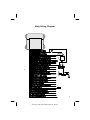
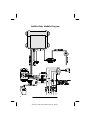
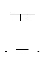
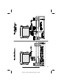
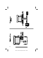
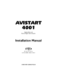
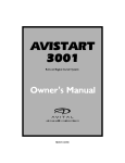
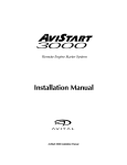
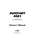
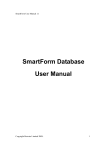
AviStart 4501 Installation Manual - 0999
I WARNING I
! Always exercise caution and common sense when operating
your AviStart system.
! This product is intended for vehicles with fuel-injection and
automatic transmissions only. NEVER attempt to remote start
a vehicle with a manual (stick shift) transmission. Serious
injury may occur with improper use.
! NEVER attempt to remote start the engine while anyone
(including pets) is in the vehicle.
! NEVER attempt to remote start the engine while the vehicle is
in an enclosed area without sufficient ventilation.
! NEVER attempt to remote start the engine while the keys are
in the ignition.
! Always be sure the gearshift selector is in "Park" and the
emergency brake is on before attempting to remote start the
vehicle.
! Keep your AviStart remote controls out of the reach of
children.
! Whenever the vehicle is being serviced or valet parked, place
the system in Protected Valet Mode to prevent accidental or
unauthorized remote starting.
AviStart 4501 Installation Manual - 0999
Table of Contents
Important Information . . . . . . . . . . . . . . . . . . . . . . . . . . . 2
Recommended Installation Tools . . . . . . . . . . . . . . . . . . . . 2
Recommended Procedures . . . . . . . . . . . . . . . . . . . . . . . 2
Main Wiring Diagram . . . . . . . . . . . . . . . . . . . . . . . . . . 3
Satellite Relay Module Diagram . . . . . . . . . . . . . . . . . . . . . 4
Pin Connectors . . . . . . . . . . . . . . . . . . . . . . . . . . . . . 5
Installation Procedures. . . . . . . . . . . . . . . . . . . . . . . . . . . 7
Control Unit . . . . . . . . . . . . . . . . . . . . . . . . . . . . . . . 7
RangeMaster™ Super Heterodyne Receiver Module . . . . . . . . . . . 7
Wireloom . . . . . . . . . . . . . . . . . . . . . . . . . . . . . . . . 7
LED Indicator . . . . . . . . . . . . . . . . . . . . . . . . . . . . . . 8
Valet Switch . . . . . . . . . . . . . . . . . . . . . . . . . . . . . . . 8
Brake Lights (Mandatory) . . . . . . . . . . . . . . . . . . . . . . . . 8
Parking Lights . . . . . . . . . . . . . . . . . . . . . . . . . . . . . . 9
Reverse Light . . . . . . . . . . . . . . . . . . . . . . . . . . . . . . 9
Interior Light Illumination . . . . . . . . . . . . . . . . . . . . . . . . 9
Trunk Release . . . . . . . . . . . . . . . . . . . . . . . . . . . . . . 9
Channel 5 Accessory . . . . . . . . . . . . . . . . . . . . . . . . . . 1 0
Remote Start Armed Signal (-) Output . . . . . . . . . . . . . . . . . 1 0
Siren/Horn (-) Output (Remote Panic Capability) . . . . . . . . . . . . 1 0
Factory Alarm Disarm (-) Output . . . . . . . . . . . . . . . . . . . . 1 0
Factory Alarm Rearm . . . . . . . . . . . . . . . . . . . . . . . . . . 1 0
Accessory Remote Start (-) Input . . . . . . . . . . . . . . . . . . . . 1 2
Glow Plug Light Input . . . . . . . . . . . . . . . . . . . . . . . . . 1 2
Ignition Switch Connections . . . . . . . . . . . . . . . . . . . . . . 1 2
Door Lock/Unlock . . . . . . . . . . . . . . . . . . . . . . . . . . . 1 3
Remote Engine Start Neutral Safety Switch Bulletin . . . . . . . . . . 1 4
Tach Wire (RPM Monitoring). . . . . . . . . . . . . . . . . . . . . . 2 1
Hood Switch (Mandatory) . . . . . . . . . . . . . . . . . . . . . . . 2 1
Power and Ground Connections . . . . . . . . . . . . . . . . . . . . 2 2
Mandatory RPM Programming . . . . . . . . . . . . . . . . . . . . . 2 2
Programmable Features. . . . . . . . . . . . . . . . . . . . . . . . . . 2 3
Programming Table for System Features . . . . . . . . . . . . . . . . 2 4
Programming Table for Remote Controls . . . . . . . . . . . . . . . . 2 5
1
AviStart 4501 Installation Manual - 0999
Important Information
Recommended Installation Tools
Voltmeter
Wire Strippers
Electric Drill & Bits
Phillips Screwdriver
Convoluted Tubing *
Solder Gun *
Wire Crimpers
Shrink Tube or Electrical Tape
* Optional
Recommended Procedures
1 . Test all circuits with a voltmeter.
2 . Make all wiring connections with the supplied solderless crimp
connectors. DO NOT twist wires or use scotch-lok connectors.
3 . Route the small and large RED, RED/WHITE and BLACK wires from the
control unit directly to the battery.
4 . Keep extensions as short as possible. Use same gauge wires for short
extensions and larger gauge wires for longer extensions.
5 . Before installing, discuss the placement of the LED indicator and valet
switch with the vehicle owner.
6. DO NOT disconnect the battery cables. Make all connections by
removing the bolts from the cable clamps without detaching the clamp.
7 . Turn off dome light or remove dome light fuse to prevent battery drain.
This device complies with Part 15 of the FCC rules. Any changes or modifications
made to the system without the express approval of Avital Technologies, Inc.
could void the user’s authority to operate this equipment.
2
AviStart 4501 Installation Manual - 0999
Main Wiring Diagram
3
AviStart 4501 Installation Manual - 0999
Satellite Relay Module Diagram
4
AviStart 4501 Installation Manual - 0999
12 Pin Connector
Pin Num ber
Wire Color
Description
1
GRAY / WHITE
Factory Alarm Disarm (-) Output
2
GRAY / BLACK
Remote Start Activated Signal (-) Output
3
TAN
Hood Switch (-) Input
4
WHITE
Door Trigger
5
BLUE
Channel 4 (-) Output (Trunk Release)
6
LIGHT BLUE
Channel 5 (-) Output
7
RED / WHITE
Parking Light Polarity Input (+) or (-) Select
8
RED / BLACK
Parking Light Output
9
RED
Battery (+)
10
WHITE / BLACK
Door Trigger Input Polarity (+) or (-) Select
11
BLACK
Battery (-)
12
VIOLET
Siren / Horn (-) Output
14 Pin Connector
Pin Number
Wire Color
Description
1
Green
Second Stage Unlock (-) Output
2
Pink
Ignition Switched +12 Volt Input
3
Blue / Orange
Accessory Remote Start (-) Input
4
Yellow
Brake Switch (+) Input
5
Yellow / Black
Reverse Light (+) Input
6
White / Green
Tachometer Input
8
Green / Black
Unlock Switch Side
7
Not Used
9
Green / White
Unlock Motor Side
10
Green / Red
Unlock Polarity (+) or (-) Select
11
Blue / Black
Lock Switch Side
12
Blue / White
Lock Motor Side
13
Blue / Red
Lock Polarity (+) or (-) Select
14
Orange / Black
Glow Plug Light (+) Input
5
AviStart 4501 Installation Manual - 0999
6 Pin Connector
Pin Number
Wire Color
Description
1
YELLOW
Starter Interrupt Switch Side
2
GRAY
Heater / AC Output
3
VIOLET
Starter Interrupt Starter Side
Primary Ignition Output #1
4
PINK
5
RED
Battery (+)
6
PINK/BLACK
Selectable Ignition/Heater-AC Output #2
6
AviStart 4501 Installation Manual - 0999
Installation Procedures
Control Unit
1 . Select a location under the dash that will allow you to use the tie wraps to
securely fasten the control unit.
2 . Mount the control unit as high as possible to ensure maximum security.
3 . Do not mount the control unit near moving parts.
4 . Avoid areas that are in the direct path of air blowing from the vents.
5 . Route wires from this point, leaving slack for ease of service.
RangeMaster™ Super Heterodyne Receiver Module
1 . Plug the receiver module WHITE connector into the control unitWHITE
plug.
2. Use tie wraps to fasten the receiver module as far from the control unit as
possible.
3 . Route the antenna cable up through the driver side windshield pillar,
behind the headliner and behind the rear view mirror.
4 . Fasten the antenna to the windshield with the double stick tape supplied
with the antenna mask facing down.
NOTE: Be sure to clean the windshield before fastening the antenna.
Wireloom
1. Plug the wirelooms securely into the control unit and satellite relay
module.
2 . Route wires from the control module and satellite relay module directly to
each connection point.
3 . Separate the small and large RED , RED/WHITE , BLACK, TAN, and
WHITE/GREEN wires.
4. Sleeve these wires with vinyl tubing or electrical tape and route them
through an existing rubber grommet into the engine compartment.
5 . If an existing grommet is not available, drill a hole and install a snap
grommet.
7
AviStart 4501 Installation Manual - 0999
LED Indicator
1 . Discuss placement with the owner.
2. Choose a location that is visible
visible from
from both
both sides
sides of
of the
the vehicle.
vehicle.
3 . Drill a ¼" hole.
4. Route the LED wires through the hole and press LED into place.
5 . Route the LED wires to the control unit.
6 . Plug the RED LED connector into the control unit RED plug.
Valet Switch
1 . Discuss placement with the owner.
2. Choose a location for the valet switch
switch that
that is
is hidden,
hidden, but
but convenient
convenient for
for
the owner to access.
3 . Drill a ¼" hole and mount the switch.
4. Route the valet switch wires to the control unit.
5 . Plug the valet switch WHITE connector into the control unit WHITE plug.
Brake Lights (Mandatory)
: As a safety feature, the unit monitors the brake light to
I CAUTION
prevent an unauthorized driver from driving the car and to switch to
normal engine operating condition. For this reason, the YELLOW
brake light input wire must be connected and the brake light must be
in working condition or the remote start will not operate properly.
1 . Turn the ignition key to the "ON" position, then press the brake pedal and
make sure the brake light illuminates.
2 . Use a voltmeter to find the one wire at the brake light switch (usually
located on the upper brake pedal arm) that shows +12 volts when you
press the brake pedal and 0 volts when the brake pedal is not pressed.
3. Connect the YELLOW wire to the vehicle brake light switch wire.
8
AviStart 4501 Installation Manual - 0999
Parking Lights
1 . If the parking lights are positive trigger, connect the RED/WHITE wire to
the battery positive (+) terminal through the 20 amp fuse assembly.
NOTE: Do not connect the RED/WHITE wire to the control unit RED wire.
2. If the parking lights are negative (-) trigger, connect the RED/WHITE wire
to control unit BLACK wire.
3. Connect the RED/BLACK wire to the vehicle parking light wire.
Reverse Light
: Some vehicles allow you to remove the gear shift
selector from "Park" even while the ignition key is not on. As a safety
I CAUTION
feature, the system will monitor the reverse wire. If the vehicle is
removed from "Park" while in the remote start mode, the system will
shut down immediately.
1 . Set the parking brake.
2 . Turn the ignition key to the "ON" position and adjust the gear shift selector
to "Reverse."
3 . Use a voltmeter to find the wire that will show +12 volts in "Reverse" and
0 volts in "Park."
4. Connect the YELLOW/BLACK wire to the vehicle’s reverse light wire.
Interior Light Illumination
1 . Connect the WHITE wire to the vehicle door trigger wire.
2. If the door trigger is negative, connect the WHITE/BLACK wire to ground.
3. If the door trigger wire is positive switching, connect the WHITE/BLACK
wire to a fused constant +12 volt source.
Trunk Release
The DARK BLUE wire provides a 1 second ground output when the dbutton
is pressed for 1-2 seconds. If the dbutton is continually pressed, the output
will stay at ground as long as the button is held. Most factory trunk releases
are positive trigger and require an optional relay.
9
AviStart 4501 Installation Manual - 0999
Channel 5 Accessory
The LIGHT BLUE wire provides a 1 second ground output when the CandD
buttons are pressed at the same time for 1-2 seconds. If the Cand Dbuttons
are continually pressed, the output will stay at ground as long as the buttons
are held. This output can be used for optional accessories such as window
roll-up/down or any other accessory requiring a (-) activation.
Remote Start Armed Signal (-) Output
The GRAY/BLACK wire will provide a continual ground output for as long as
the vehicle is in the remote start mode. This output can be used for additional
ignition, starter or heater/AC relays.
Siren/Horn (-) Output (Remote Panic Capability)
The VIOLET wire will provide (-) output when the C button is pressed for 3-4
seconds. The (-) output can be programmed for a continual output when
adding an optional siren or a pulsed output when tapping into the vehicle (-)
horn wire. See the "Programming Table for System Features" on page 31.
Factory Alarm Disarm (-) Output
The GRAY/WHITE wire will provide a 1 second ground output when the
START button is pressed.
1 . Arm the vehicle factory alarm system.
2. Use a volt/ohmmeter to locate the one wire that will show ground only
when the driver door key cylinder is held in the unlock position.
NOTE: Most factory alarm/disarm wires will show 8-12 volts while
armed. A few vehicle disarm wires will rest at a neutral state while
armed. Regardless of type, both types will change to ground when the
key cylinder is turned to unlock.
3 . Connect the GRAY/WHITE wire to the factory alarm disarm wire.
Factory Alarm Rearm
The system incorporates the ability to rearm a vehicle's factory alarm system if
it is necessary to disarm the factory alarm in order to remote start the vehicle.
While in the remote start mode, if you were to remotely shut off the engine or
allow it to "time out," three seconds later the system will turn on the interior
lights for five seconds and activate the door locks for two seconds while the
interior lights are on.
There are type types of factory alarm systems and this procedure will allow
you to rearm either type.
10
AviStart 4501 Installation Manual - 0999
Type 1
This type of alarm system does not have a factory alarm arm wire. In order to
arm this type of system, simply press the vehicle lock switch while the driver
side door is opened and then close the door. The factory alarm system will
then arm automatically in 10-20 seconds (typically) after the interior lights
have turned off.
For this type of system you do not need to make any additonal wire
connections. (You do need to be connected the vehicle interior lights and
power door locks.)
Type 2
This type of alarm does have a separate factory alarm arm wire. In order to
arm this type of system, close the doors, hood and trunk. Turn the driver side
door key cylinder to the lock position for one second. The factory alarm will
arm automatically in 10-20 seconds (typically).
To rearm the factory alarm system you will need to connect the vehicle arm
wire to the Avital lock wire (which is already connected to the vehicle lock
wire). See the diagrams below.
11
AviStart 4501 Installation Manual - 0999
Accessory Remote Start (-) Input
The BLUE/ORANGE wire will accept a (-) input pulse to activate the remote
start.
Glow Plug Light Input
The AviStart can start a diesel engine by one of two methods.
Pre-ignition
The module can be programmed to turn the ignition "ON" for 15 seconds
before the starter engages. This will allow the glow plugs time to warm up and
the glow plug light to turn off.
Glow Plug Light Monitoring
The glow plug light (+) input wire will monitor the glow plug light in the
dashboard. When a remote start is attempted, the ignition will turn on and
when the glow plug light turns "OFF" the engine will start
1 . Locate the glow plug light wire that will show (+) 12 volts while the
ignition key is on and the glow plug light wire is illuminated.
2 . Connect the AviStart ORANGE/BLACK wire to the vehicle glow plug light
wire.
NOTE: Do not use both "pre-ignition" and "glow plug light monitoring" at
the same time (use one or the other).
Ignition Switch Connections
NOTE: Because these wires can draw high current, we recommend that they
be soldered and shrink tubed or taped. If only one PINK wire is needed, tape
the end of the second PINK wire to prevent a short circuit. The main control
module has an 18 ga PINK wire that must be connected to the vehicle
ignition wire with one of the satellite module 14 ga wires.
Ignition #1 Ignition #2
The satellite relay module has two onboard 30-amp relays. Most vehicles have
only one ignition wire necessary to start the vehicle. Some vehicles have two
ignition wires. Make all wire connections at the ignition switch wire harness.
1 . Use a voltmeter to locate the wire(s) that show +12 volts while the ignition
key is in the "ON," "CRANK" and "RUN" positions and 0 volts when the
ignition key is in the "OFF" position.
2 . Connect the 18 and 14 ga PINK wires to the vehicle ignition wire.
3. If the vehicle has a second ignition wire, connect the 14 ga PINK/BLACK
wire to the second ignition wire.
12
AviStart 4501 Installation Manual - 0999
Heater/AC #1 — Heater/AC #2
The satellite relay module has one onboard 30-amp relay. Most vehicles have
only one heater/AC wire. If an additional heater/AC wire is required to activate
the vehicle’s heater/AC system, follow the directions under step #5 on the page
12. Do not use the GRAY wire to power more than one heater/AC wire.
1. Use a voltmeter to find the wire(s) that show +12 volts when the ignition
key is in the "ON" position, 0 volts while the starter is cranking and +12
volts while running.
2 . Cut this wire in half. Start the vehicle and turn the blower switch on. The
blower should not turn on.
3. Connect the GRAY wire to the heater/AC wire.
4. If the vehicle has a second heater/AC wire, connect the PINK/BLACK wire
to the second heater/AC wire.
5 . Selectable ignition or heater/AC output #2– the PINK/BLACK wire can be
programmed to supply an ignition or heater/AC output. The satellite
module is factory programmed for ignition #2. To change the
PINK/BLACK wire from ignition to heater/AC, follow the procedure below.
• Open the satellite relay module (2 screws).
• Remove the jumper terminal from "IGN2" terminal.
• Insert the jumper terminal to the "ACC2" terminal.
Starter
Review the "Safety Bulletin" and diagrams on pages
I WARNING:
11-13 prior to installing the starter system.
1 . Use a voltmeter to find the wire that shows +12 volts while the ignition
key is in the "CRANK" position only and 0 volts while the key is in the
"OFF," "ON" and "RUN" positions.
2. Cut the wire in half. Test by trying to crank the starter with the ignition
key. If it will not crank, you have the correct wire.
3 . Connect the YELLOW wire to the ignition switch side of the starter wire.
4. Connect the VIOLET wire to the starter solenoid side of the starter wire.
Door Lock/Unlock
The system has onboard door lock relays to lock and unlock all of the doors as
well as a two-stage unlock. The diagrams on pages 17-20 will illustrate
standard lock/unlock and two-stage unlock.
13
AviStart 4501 Installation Manual - 0999
Remote Engine Start Neutral Safety Switch Bulletin
A neutral safety switch is a mechanism on almost every vehicle equipped
with an automatic transmission. The neutral safety switch prevents the
vehicle from starting while the gear shift selector is in "Reverse" or "Forward"
gear positions.
There are basically two types of neutral safety switches. The most common
is the mechanical (separate) neutral safety switch. A small group of vehicles
use a combined neutral safety switch.
Type "A" (separate)
The mechanical neutral safety switch is located between the ignition switch
and the starter solenoid. The starter wire runs directly from the back of the
ignition switch to the neutral safety switch and then to the starter solenoid.
When adding a remote engine starter, make starter wire connections as close
to the ignition switch as possible to ensure your connections are between
the ignition switch and the neutral safety switch.
Type "B" (combined)
Some vehicles combine the neutral safety switch and the steering column
shift mechanism together. The starter wires run from the "combined" switch
directly to the starter solenoid. The remote start wire connection cannot be
made between the ignition switch and the neutral safety switch. As a result,
if the vehicle was left in gear with the key in the ignition and not in the
locked position, the vehicle could move forward or backward if a remote
start attempt was made.
The combined type neutral safety switch requires an additional relay to
prevent the vehicle from remote starting while the key is in the ignition. Use
the attached test procedure and relay wiring diagrams. Install the complete
remote start unit and test all safety features before conducting the test
procedure.
Currently, the only vehicles with the combined neutral safety switch that
Avital is aware of are General Motors trucks, GM sport utility vehicles, GM
column shift passenger cars and Dodge Dakota pickup trucks. There may be
additional vehicles with the combined neutral safety switch that require the
additional relay.
14
AviStart 4501 Installation Manual - 0999
NOTE: Use the following test procedure upon completion of every remote
start regardless of the make and model of the vehicle
Test Procedure
Be sure there is at least 5 feet of unobstructed
clearance at the front and rear of the vehicle. Make sure to alert
I CAUTION:
anyone near the vehicle you are testing that the vehicle may move
forward slightly.
1 . Apply the parking brake.
2 . Turn the ignition key to the "ON" position and place the vehicle in
"DRIVE."
3. Turn the ignition as close to the "OFF" position as possible. (Most
vehicles will not allow the key to turn off completely.)
4 . Place your foot over the brake pedal without touching it. Be prepared to
step on the brake if the starter engages.
5. Activate the remote engine starter.
6. If the vehicle starter engages, immediately press the brake pedal to
disengage (shut down) the remote start. You have a "combined" type
neutral safety switch and you will have to add an additional relay as
shown in the diagram.
7 . If the vehicle starter does not engage, no additional relays are required.
All vehicles have a "key in the ignition" reminder circuit (key minder) that
will sound a chime or buzzer while the key is in the ignition and the driver’s
door is open. The following diagrams will illustrate how to interface the
key-minder wires and a relay to prevent the vehicle from remote starting
while the key is in the ignition.
The wire color codes are subject to change. Check all wires with a
volt/ohmmeter. If you have any questions, please contact the Avital
Technical Support Department.
15
AviStart 4501 Installation Manual - 0999
Gen eral Mo tors Sport Util ity Ve hi cles, Trucks and
Col umn Shift Pas sen ger Ve hi cles
Dodge Da kota Pickup Trucks
16
AviStart 4501 Installation Manual - 0999
17
AviStart 4501 Installation Manual - 0999
18
AviStart 4501 Installation Manual - 0999
19
AviStart 4501 Installation Manual - 0999
20
AviStart 4501 Installation Manual - 0999
Tach Wire (RPM Monitoring)
The AviStart is designed to monitor the vehicle RPM by connecting directly to
the vehicle tachometer wire which is usually located at the distributor,
ignition coil or diagnostic plug. On most vehicles, the tach wire is easily
accessible. If the tach wire is not accessible, there are several alternative
choices. Contact Avital Technical Support Department for alternate choices.
The following procedure for testing the vehicle tach wire is not exact and may
vary with different vehicle make, model and year. We recommend that you
refer to your autofax documents for tach color code and location information.
1 . Set your voltmeter to the AC voltage scale.
2 . Start the vehicle. Use the voltmeter to find a wire that will show 1 to 5
volts AC while the vehicle is idle and increase an additional 1 to 5 volts
AC when the engine RPM is raised to 3000-4000 RPM.
3. Connect the WHITE/GREEN wire to the vehicle tach wire.
Hood Switch (Mandatory)
As a safety precaution, the hood switch prevents the vehicle from starting
when the hood is open. If the vehicle is in the remote start mode and the hood
is opened, the remote start will immediately shut down.
1. Choose a location under the hood away from direct exposure to water or
water drain areas.
2 . Check for proper hood clearance.
3 . Make sure the hood switch will make contact with a flat surface on the
hood when closed.
5
4 . Drill a /16 " mounting hole.
5. Mount the hood switch.
6 . Connect the TAN wire to the hood switch.
7. Make sure the hood makes contact with hood switch when closed and
presses the hood switch straight down to prevent wear.
21
AviStart 4501 Installation Manual - 0999
Power and Ground Connections
: Do not plug in the system fuses until the final step
below.
I CAUTION
1 . Connect the 18 ga RED wire to one end of a supplied 20 amp fuse
assembly.
2. If the vehicle parking lights are positive trigger, connect the RED/WHITE
wire to one end of the other supplied 20 amp fuse assembly.
3. Connect the BLACK wire to the 10 mm ring terminal.
4. Connect the 10 ga RED wire to one end of both 30-amp fuse assemblies.
5. Connect the other ends of the 18 ga RED and RED/WHITE wire fuse
assemblies to the 10 mm ring terminal.
6. Connect the other end of the 10 gaRED wire fuse assemblies to the other
10 mm ring terminal.
7 . Remove the (+) and (-) battery bolts. Do not disconnect the battery clamps.
8 . Connect the empty fuse assemblies to the (+) battery terminal.
9 . Connect the BLACK wire to the (-) battery terminal.
10. Inspect all wiring. Make sure all wires are connected correctly.
11. Install the 5 amp fuse in the 18 ga RED wire fuse assembly.
12. Install the 20 amp fuse in the RED/WHITE wire fuse assembly.
13. Install the two 20 amp fuses in the 10 ga RED wire fuse assemblies.
Mandatory RPM Programming
In order to remote start the vehicle engine and prevent over-grinding of the
starter motor, the engine RPM must be programmed into the system memory.
The AviStart has a built-in piezo beeper for audible programming confirmation.
1 . Start the engine with the ignition key. Let the engine warm up until it
reaches a normal idle RPM (typically 700-900 RPM).
2 . Turn the ignition key off.
3 . Start the engine with the ignition key.
4. Within 10 seconds of starting the vehicle, begin flicking the valet switch
on then off 13 times (counting the piezo beeps).
NOTE: Stop on the 13th beep. See the "Programming Table for System
Features" on page 24.
5 . Press and hold the remote s button.
6 . The parking lights will flash two times to confirm the RPMs have been
memorized.
7 . Release the s button.
22
AviStart 4501 Installation Manual - 0999
Programmable Features
All AviStart system and remote control programmable features are
accomplished by turning the ignition key to the "ON" position or starting the
engine (see "Mandatory RPM Programming") and flicking the valet switch on
and off a preset number of times. The system has a built-in piezo beeper for
audible programming confirmation.
The AviStart also allows the user to add new remote controls in one step,
delete lost or stolen remote controls or rearrange the factory preset remote
control functions.
1 . Remove the system from Protected Valet Mode. Programming cannot be
accessed while the system is in Protected Valet Mode indicated by the
LED on solid red.
2 . Select the feature you wish to program from the "Programming Table for
System Features" or the "Programming Table for Remote Controls" on
pages 24-25. Note the number of beeps associated with that feature.
3 . Turn the ignition key to the "ON" position.
4 . Within 10 seconds, begin flicking the valet switch on and off. The built-in
piezo beeper will beep once each time you flick the switch on then off.
5. Continue flicking the switch on and off, counting the number of beeps.
NOTE: Stop when you reach the number of beeps associated with your
chosen feature.
6 . Follow the "Secondary Action." You will hear a number of beeps to
confirm that you have changed the setting of that feature.
7 . Turn the ignition key "OFF."
8 . Repeat steps 1-7 for any other feature you wish to program.
23
AviStart 4501 Installation Manual - 0999
Programming Table for System Features
Feature
Factory
Setting
No. of
Beeps
Secondary Action
Door Lock/Unlock Output
Duration
(1 or 3 Seconds)
1 Second
4
Wait 3 seconds, the piezo beeper will beep
once for 3 seconds, twice for 1 second.
2 Pulse Lock
1 Pulse
5
Wait 3 seconds, the piezo beeper will beep
once for 2 pulse, twice for 1.
2 Pulse Unlock
1 Pulse
6
Wait 3 seconds, the piezo beeper will beep
once for 2 pulse, twice for 1.
Ignition Control
Lock/Unlock
ON
7
Wait 3 seconds, the piezo beeper will beep
once for OFF, twice for ON.
0 or 3 Second Delay for
Ignition-Controlled Door
Lock
0 Second
8
Wait 3 seconds, the piezo beeper will beep
once for 3 seconds, twice for 0 seconds.
RPM Door Lock
OFF
9
Wait 3 seconds, the piezo beeper will beep
once for OFF, twice for ON.
Passive Starter Disable
OFF
10
Wait 3 seconds, the piezo beeper will beep
once for OFF, twice for ON.
Remote Lock Starter
Disable
ON
11
Wait 3 seconds, the piezo beeper will beep
once for OFF, twice for ON.
Horn/Siren Output
Horn
12
Wait 3 seconds, the piezo beeper will beep
once for Siren, twice for horn.
13
See "Mandatory RPM Programming"
on page 21.
Mandatory RPM
Programming
Remote Start Run Time
20 or 30 Minutes
20 Minutes
14
Wait 3 seconds, the piezo beeper will beep
once for 30 minutes, twice for 20 minutes.
Remote Start Pre-Ignition
2 or 15 Seconds
2 Seconds
15
Wait 3 seconds, the piezo beeper will beep
once for 15 seconds, twice for 2 seconds.
Temperature-Controlled
Starting
Off or 5°F (-15° C)
OFF
16
Wait 3 seconds, the piezo beeper will beep
once for OFF, twice for 5° F (-15°C).
17
Wait 3 seconds, the piezo beeper will beep
once for -7°F (-20°C), twice for -22°F
(-30° C).
_
_
7°F (-20°C) or 22°F
(-30°C)
24
AviStart 4501 Installation Manual - 0999
Programming Table for Remote Controls
Feature
Factory
Setting
No. of
Beeps
Secondary Action
Remote Door Lock/Panic
CButton
18
Press the CButton, the piezo
beeper will beep 1 time
Remote Door Unlock
DButton
19
Press theDButton, the piezo
beeper will beep 2 times
Remote Engine Start
sButton
20
Press thesButton, the piezo
beeper will beep 3 times
Remote Trunk Release
c Button
21
Press the c Button, the piezo
beeper will beep 4 times
Temperature Controlled Start
Active/Inactive
C+s
22
Press the C+ sButton, the piezo
beeper will beep 5 times
Remote Accessory Output (-)
C+D
23
Press the C+DButton, the
piezo beeper will beep 6 times
24
Press the CButton, the piezo
beeper will beep 1 time
25
Wait 3 seconds, the piezo beeper
will beep twice, all codes are
erased out of memory.
All Learn
Delete All
Button
Button
CButton
25
AviStart 4501 Installation Manual - 0999
© 1999 Avital Technologies, Inc., A Division of Clifford Electronics
Part Num ber: 32- 4501/AviStart 4501IM/ 0999
AviStart 4501 Installation Manual - 0999