1
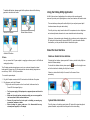
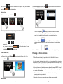
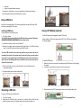
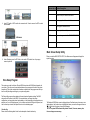
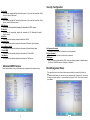
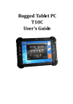
Main Features
AcuTab-M
Quick Guide
Platform: Intel® Cedar Trail Platform (N2600+NM10)
GPU: Intel ATOM N2600 1.6GHz Dual core
Chipset: Intel® NM10 Express Chipset
System Memory: 2GB DDRIII 800 SO-DIMMM
Storage: 1 x 32G SATA Slim Half-Size Solid State Disk
LCD Panel: 10.4-inch LED Backlight Screen
10.4“ XGA (1024x768) 340nits LCD + T/P(Polarizer + 1/4 λ+ AR)
Touch Panel
5-wire Resistive Touch Screen
Audio: -1 x High Quality Speaker (2W)
-Internal Microphone : 1 x in front Bezel
TPM:
1 x Compatible with TPM1.2 (option)
Communication :
- 10/100Mbps Ethernet (via adapter to mini USB port)
- Wi-Fi IEEE 802.11 a/b/g/n; Bluetooth 4.0
- 3G,4G LTE(Optional)
- Webcam:
Front - 2 Mega-pixel Camera
Rear - 5 Mega-pixel Camera with LED Flash light
- Automatic Focus
- Automatic white balance Power
Adapter :
AC Input, 100V ~ 240VAC, 50~60Hz
DC Output, [email protected], 65W
Battery
Internal Battery - Smart Lithium Polymer Battery, 3800mAH, 7.4V
Mechanical & Environmental
Dimension
277.8 x 206 x 26.5mm
Weight
1.1kg
Operation System
OS
Windows 7 Pro, WES7P 32bit
Rugged Design
Drop
6ft drop ploywood on concrete
Water/Dust Resistance
IP65
Operation temperature
-20°C to +50°C
Storage Temperature
-30°C to +70°C
Humidity
5-95% without condensation
Acura Embedded Systems Inc.
Environment
1
Viewing AcuTab-M
Before starting to set up the AcuTab-M, get familiar with the locations and purposes of
controls, connectors and ports, which are illustrated in the figures below. When placed
upright on the desktop, the front panel of AcuTab-M appears as shown in
below.
Camera / 2 Mega-pixel (Front-facing)
The built-in camera can be used as a communication device for allowing you to
capture images, record videos, and have video chats. It is 2M pixels and transmitting
instant image through network for conference.
Camera / 5 Mega-pixel (Rear-facing)
The built-in high resolution camera can be used as a communication device
for allowing you to capture images, record videos, and have video chats.
Power / Storage / RF wireless
Keeps you informed of your system’s current power status, storage access status,
and RF wireless devices ON/OFF status.
1. Power LED Indicator
2. Storage Access
3. RF ON/OFF
F1 Button
F1=explorer
F2 Button
F2=Windows Media Player
F3 Button
F3=OnScreen keyboard (osk)
F4 Button
F4=Task Manager
F5 Button
F5=Calculator
Fn Button
Fn = Hotkey Utility
Power LED Indicator
Letting you know that system is turned on and indicate the battery charging
status.
•
Lights green when the system is powered on and battery is discharging
•
Lights amber when the system is powered on and battery is charging
•
Lights blinking amber when the system is in S3 sleep mode and battery
is charging or lights blinking green when the system is in S3 sleep mode
and battery is fully charged
•
Lights off when system is powered off or the battery is fully charged.
Storage Access
When LED blinking white indicates that the system is accessing the internal storage drive.
RF ON/OFF Indicator
Implement Secure Attention Sequence (SAS)
Fn+F3 Button (SAS) Similar function as pressing Ctrl-Alt-Delete on a standard
keyboard
F1 KEY -LEFT ARROW
Function Key
F2 KEY -UP ARROW
mapping during boot F3 KEY -ENTER
(for Windows
F4 KEY -RIGHT ARROW
system recovery)
F5 KEY -DOWN ARROW
When LED turns on, white LED indicates that a wireless device(Wifi/Bluetooth/3G/LTE) is
activated. When LED turns off, it indicates that all RF devices are being disabled.
Programmable Function Buttons (F1~F5)
These buttons is programmable to execute specific software application. When you
program the application to launch, please write this directory as listed below into the
configuration file, then the system will aware and execute this application.
2
3
[Setup]
F1_EXE="c:\windows\explorer.exe"
F1_PARA=""
F1_PATH=""
F2_EXE="C:\Program Files\Windows Media Player\wmplayer.exe"
F2_PARA="/prefetch: 1"
F2_PATH=""
F3_EXE="C:\WINDOWS\system32\osk.exe"
F3_PARA=""
F3_PATH=""
F4_EXE="C:\WINDOWS\system32\taskmgr.exe"
F4_PARA=""
F4_PATH=""
F5_EXE="C:\WINDOWS\system32\mspaint.exe"
F5_PARA=""
F5_PATH=""
The configuration file is located under drive C: root directory as
"c:\FKeySet.txt"
Barcode Buttons (F1 / F4)
Please press F1 or F4 function keys to trigger to scan the barcode when the optional
barcode scanner snap-on module is installed.
If your system does not have this module, these buttons can be programmable to
execute specific software application. When you program your application, please write
this directory as listed below into your configuration file, then the system will aware and
execute this application.
External Battery Connector
To install the External Battery, please remove the cover of external battery connector before
snap the battery pack into the external battery connector.
Speaker
Integrated stereo speaker for sound and audio output for your multimedia
presentations or listening pleasure.
Protective Rubber
To prevent system harm from vibration or shock, the system is designed with installing
protective rubber on both sides.
3.5mm Headphone Jack
Allows you to connect an external stereo headphone with MIC for personal listening and
sound recording.
USB Ports
The two USB type-A ports allows you to connect USB 2.0-compliant devices (for
example, mouse, keyboard and so on) to your Tablet PC.
Ethernet port
The 10/100Mbps Ethernet port allows you to connect to other computers/networks through a
local area network (LAN) via a mini-USB to RJ45 adapter cable provided in the accessory
box.
Power Button
Switch the computer power on and off, or resumes whenever it is in Suspend mode (by OS
define).
Lock Button
To prevent the screen or function keys have been touched accidentally. The screen will
appear Lock message.
To make the system back to work, press the Lock button again to disable the lock
function, the screen will appear Unlock message.
RF Button
Press this button to enable or disable power of the Wi-Fi, Bluetooth or 3G devices.
When you press the RF Button, the screen pops-up the option list for your selection.
You can see all functions in this option list have been ticked. To close any function, please
touch the option to close the execution as shown in the following graphics.
F1_EXE="c:\windows\explorer.exe"
F1_PARA=""
F1_PATH=""
F4_EXE="C:\WINDOWS\system32\taskmgr.exe"
F4_PARA=""
F4_PATH=""
Accessory Door
By removing the four screws on top side of the system, allows you to install optional snapon module.
4
Disable Wi-Fi function
Disable Bluetooth function
5
Disable 3G function
To activate the function, please again tick the option as shown in the following
graphics to make the device enable.
Using the Hotkey Utility Application
AcuTab-M has numbers of applications on the control panel for executing specific
command. It provides you to adjust brightness, volume, launch webcam, and switch monitor.
This user interface provides specific mobile utility to let you easily setup some helpful
functions and aware the system status directly.
Activate Wi-Fi function
Activate Bluetooth function
This utility also let you adjust some function to fit the requirements, such as brightness
and volume adjustment, webcam launch, screen orientation and monitor switching.
Furthermore, it also provides system information for your reference, such as battery status,
RF setting with its signal strength, firmware (BIOS & EC) version information. Besides
these features, you can press the soft button to hibernate this system.
About the User Interface
Activate 3G function
Enable or disable the User Interface
DC-Jack
Lets you connect the AC power adapter in supplying continuous power to AcuTab-M and
recharging the battery.
The AC adapter provides external power source to your system and charges the internal
battery pack at the same time. The AC adapter also has an auto-switching design that can
connect to any 100VAC ~ 240VAC power outlets.
To connect the power adapter:
1.
Plug the AC adapter connector to the DC-Jack socket on the left side of the system.
2.
Plug the power cord to the AC adapter.
Plug the other end of the power cord to a live wall outlet, at the same time, the
Power LED at front panel lights up.
•
•
•
•
For the power supply of this equipment, an approved power cord has to be
used.
Make sure the socket and any extension cord(s) you use can support the
total current load of all the connected devices.
Remove all power from the device prior to installing or removing any
accessories, hardware, or cables
Before cleaning the system, make sure it is disconnected from any
external power supplies (i.e. AC adapter).
6
To display the User Interface, please press the Fn button or point the Hotkey Utility icon
located on Windows desktop.
button on the top right corner
To close the User Interface function, please press the
on this User Interface for disabling this utility from the screen.
If there is no action within this utility in 5 seconds, the UI screen will close
automatically.
System Status Information
This utility shows you the battery capacity status, RF status with its signal strength and
system information, and provides the control panel for the function setting.
7
For RF status:
The following RF status shows you that the system is equipped with Wi-Fi, and Bluetooth
functions. If you want to close either of these functions, please refer section for how to disable
it.
The following signal strength shows you that the Wi-Fi function is connecting currently, the
stronger the signal strength, the more scale will show on the bar. If there is no module in the
system, there will be no status scale in the following status bar.
For battery capacity status:
AcuTab-M is equipped with one internal battery and one optional external battery.
For System Information:
The battery capacity status shown below advises you, that only one internal battery is
nd
embedded with the system with fully charged, and there is no 2 optional battery installed
in the system.
The system information shown on the left shows you the utility version, BIOS
and EC version and you can use them for customer service when asked.
Brightness Control
If the system installs both the 1st internal battery and 2nd optional battery, the illustration
shown below indicates its current charging status and capacity.
For brightness adjustment, press the Brightness
icon.
If 1st battery capacity drops to 15%, the system will display the following warning message for 5
seconds.
When you press it, the brightness control panel is appeared as follows:
8
9
You can click
or
scale bar
to reduce or increase the LCD brightness. Also, you can slide the
For Monitor switch, press the Monitor Switch
display mode within following four options.
to pop-up the selection bar for choosing the
to set the brightness.
Volume Control
icon.
For Volume adjustment, press the Volume
When you press it, the Volume control panel is appeared as follows:
You can click
incrementally.
or
to reduce or increase the audio volume
Also, you can slide the scale bar
tick the Mute
You can click Extend
to display the different contents on the default screen
and external display device. You only can adjust the resolution on the external display
device.
to set the audio volume. You can
to mute the audio.
Launch Webcam Utility
You can click Projector only
to display on external projector only.
Powering on for the first time
icon to launch the Webcam utility. Or can
For Webcam Launch, press the Webcam
access the Webcam
to display the same contents both on the default
You can click Duplicate
screen and external display device. The resolution on these two display modes are
same, it is not available to adjust the resolution on the external display mode.
icon located on desktop.
The Power/Resume button is found on the left side of the AcuTab-M. Press the
Power/Resume button to start your system and check that if the Power LED turns on.
After a few seconds, the system’s display will turn on and your system will begin to execute
the Power On Self Test or POST to check if all system components are running properly. Any
error found during the test will be displayed on the screen.
After the test, the screen will also display a message "press <F2> to enter SETUP". You don’t
need to run this program at the moment as your dealer already made the necessary settings for
your computer optimal operation.
After the test has completed, your computer will start to search and boot up the
operating system from your hard drive.
Before setting up the system, please make sure the following items are available.
Monitor Switch
10
11
•
•
Keyboard
Mouse (for system software installation)
A keyboard is an input device; a mouse is a pointing device. Please connect these two
devices as graphics shown below to interact with your system.
Using a SIM Card
AcuTab-M can be equipped with a 3.5G module (optional) that can work with SIM card. (SIM
card is always working with 3.5G module.)
Using a GPS Module (optional)
Inserting a SIM Card
To insert a SIM card into the SIM Card slot:
1. Turn off your System.
The AcuTab-M must be powered off while the SIM Card is being connected. Otherwise, it
is harmful to both devices and it shortens the life of these devices.
AcuTab-M is designed with equipped the optional GPS module.
Before installing the GPS module, please adjust to DIP 2-3 for GPS mode as indicated in
the following diagram.
2. Unscrew the accessory cover on top of the Tablet PC.
3. Make sure the clipped corner facing inward with the gold fingers of the SIM card facing
down. Push the SIM Card firmly but slowly into the SIM Card slot.
To insert a SIM card into the slot, please pay attention only one correct side can be
accepted for the card slot. If you cannot insert the card into the slot or you had inserted
the card but it is not recognized by the AcuTab-M, please remove the card and insert it
again. To prevent the damage made both on card and the slot, never forced an entry into
To install the GPS Module:
the slot with incorrect side.
1.
4. When the full length of the card is almost inside the slot, the SIM Card will be
automatically detected.
2.
Make sure the system is turned off, internal battery detect DIP switch set to off and unplug
AC adapter.
Unscrew four screws from the accessory door on top of the system.
3.
Mount and secure the GPS Tracker daughter board into the mainboard with screws.
5. Place the accessory cover back and screw it firmly.
Removing a SIM Card
To remove a SIM Card from the SIM Card slot:
1.
2.
Turn off your system.
Slightly push the SIM card to pop it out and pull it out directly. When the SIM card has
moved out a space out of the slot, hold the edges of the card and slowly slide it out.
12
GPS Tracker daughter Board
13
Function Key (s) Function Description
Moves cursor left to select Screens
4.
Insert FFC cable of GPS module into connector slot. Screw to secure the GPS module
onto the tablet.
GPS Module
/
Moves cursor up or down to select items
+/-
To change option for the selected items
<Tab>
To bring up the selected screen
<F1>
To display the General Help screen
<F10>
To save changes and exit the BIOS SETUP UTILITY
<ESC>
To jump to the Exit Screen or exit the current screen
Main Screen Setup Utility
5.
Under Windows, press the RF Button, and enable GPS module from the pops-up
screen’s option list.
When you enter the BIOS SETUP UTILITY, the Main screen will appear and display the
system overview.
Bios Setup Program
This system comes with a chip from Phoenix BIOS that contains the ROM Setup information for
your system. (This chip serves as an interface between the processor and the rest of the system
components.) This section explains the information contained in the Setup program and tells you
how to modify the settings according to your system configuration.
The Setup utility program allows updates to the main board configuration settings. The BIOS
setup values will be saved in the CMOS. It is executed when you change the system
configuration, you change the system backup battery, or the system detects a configuration error
and asks you to run the Setup program. You must have connected a USB type of keyboard, and
Use the arrow keys to select, and press Enter to run the selected program.
Function Key
Please check the following table for the function description of each direction key.
14
The Standard CMOS Setup screen is displayed above. Each feature may have one or more
option settings. Use the arrow keys to highlight the feature you want to change and then use
“ ” or “ ” to select the value you want for that feature.
NOTE: The system BIOS automatically detects Phoenix, Processor, memory size,
thus no changes are necessary.
15
Security Configuration
System Date
To set the date, highlight the Date field and then press +/- keys to set the current date. Follow
the month, day and year format.
System Time
To set the time, highlight the Time field and then press +/- keys to set the current time. Follow
the hour, minute, and second format.
BIOS Version
The system will automatically displays the information of BIOS version.
EC Version
The system will automatically displays the information of EC (Embedded Controller)
firmware version.
Build Time
The system will automatically displays the build time of BIOS.
Processor Type
The system will automatically displays the information of Processor Type and speed.
System Memory Speed
The system will automatically displays the information of System Memory Speed.
L2 Cache RAM
The system will automatically displays the information of L2 Cache RAM.
Total Memory
The system will automatically displays the information of Total Memory.
Advanced BIOS Features
For Advanced Settings, it lets you define the device configuration when system booting.
Set Supervisor Password
This field let you set or clear the Supervisor account’s password.
Set User Password
This field let you set or clear the User account’s password.
TPM Support
Lets you activate or de-activate the TPM function by selecting Enabled or Disabled option.
(For the non-TPM SKU, this item will display “no detected”.)
Boot Management Setup
This page allows you to set the search drive sequence where the system will try to boot up
first.
To select the boot device, you can use the up or down arrow key, then press <+> to move up
the device in the list or press <-> to move down the device in the list. To exit from this menu,
press <Esc>.
16
17
Exit Control
Exit Saving Changes
When you select this option, it will pop-out the following message, “Save configuration
changes and exit setup?” Select [OK] to save the changes and exit the BIOS SETUP
UTILITY.
Exit Discarding Changes
When you select this option, it will pop-out the following message, “Discard changes and
exit setup?”. Select [OK] to exit the BIOS SETUP UTILITY without saving any changes.
Load Setup Defaults
When you select this option, it will pop-out the following message, “Load optimal
defaults?” Select [OK] to load the default values for all the setup configurations.
Save Changes
When you select this option, it will pop-out the following message, “Save changes?” Select
[OK] to save all changes.
With the unique set of products, Acura Embedded Systems remains committed to its goal of
providing trouble-free and customer-friendly service. A special customer service unit has been
set up specifically to cater to our esteemed customers' needs.
Technical Support:
For technical support contact your Salesperson
[email protected]
Mailing address:
Acura Embedded Systems Inc.
Unit #1, 7711-128th Street, Surrey, BC V3W 4E6, CANADA
Ph: (604) 502-9666 Fax: (604) 502-9668
Toll Free 1-866-502-9666
18