1
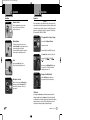
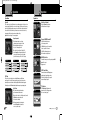
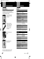
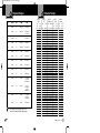
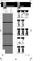
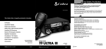
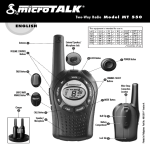
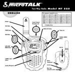
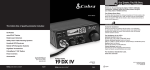
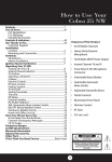
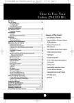
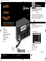
19DXIVEU_MANL:19DX 6/4/09 8:34 AM Page 17
Our Thanks and
Customer Assistance
Introduction
Thank you for purchasing the Cobra 19 DX IV EU CB Radio
Transceiver. Properly used, this Cobra product will give
you many years of reliable service.
NOTICE!
Owner’s Manual
Before using this transceiver, please check that the radio has been programmed on the
frequency band specifications and operating modes allowed by the regulations valid in the
country where the product is used. If not, please proceed to modify the frequency band
programming, as described in this owners manual page 5. This transceiver is programmed at
the factory on the EU frequency band (40 CH AM 1W/40 CH FM 4W).
Customer Assistance
The Cobra line of quality products includes:
Customer Assistance
Downloaded from www.cbradio.nl
Should you encounter any problems with this product, or not understand
its many features, please refer to this owner’s manual. If you require further assistance after
A
reading this manual, please contact your local dealer.
CB Radios
microTALK® Radios
This equipment is intended for use in:
Radar/Laser Detectors
Safety Alert® Traffic Warning Systems
This equipment is intended for use in:
HighGear® Accessories
AT
BA
BE
BG
CH
CY
CZ
CobraMarine® VHF Radios
Power Inverters
Accessories
For more information or to
order any of our products,
please visit our website:
www.cobra.com
Nothing Comes Close to a Cobra®
English
Nothing Comes Close to a Cobra®
GB
GR
HR
HU
IE
IS
IT
LT
LV
LU
MK
MT
RU
NL
SE
NO
SI
PL
SK
PT
TR
RO
UA
RS
Countries of use
For Warranty, Product Service and
Accessory Information
Please contact your local dealer or distributor.
See the enclosed leaflet that provides contact
information for the Cobra international
distributors.
MOBILE RADIO
19 DX IV EU
DE
DK
EE
ES
FI
FR
Printed in China
Part No. 480-526-P
Version C
English
© 2009 Cobra Electronics Corporation
6500 West Cortland Street
Chicago, Illinois 60707 USA
www.cobra.com
A1 English
19DXIVEU_MANL:19DX 6/4/09 8:34 AM Page A2
Product Features
Introduction
Introduction
Product Features
Channel 9/
NOR/Channel 19
Button
AM/FM
Button
•
TX Indicator
Icon
S/RF
Power Meter
Product Features and
Trademark Acknowledgement
LCD Channel
Display
Product Features
NOTES
•
Features
• Instant
Channels 9/19
NOR
• Compact
Size
• Dynamic
Microphone
• Nine Foot
Microphone
Cord
• Front Panel
Microphone
Connector
Talk
Button
Microphone Connector Detail
Shield
RX
TX
• RF Gain
Microphone
Connector
On-Off/
Volume Knob
Squelch/
RF Gain Knob
Channel
Selector Knob
External
Speaker Jack
Audio
Trademark Acknowledgement
•
Cobra®, Nothing Comes Close to a Cobra® and the snake design are registered trademarks
of Cobra Electronics Corporation, USA. Cobra Electronics Corporation™ is a trademark of
Cobra Electronics Corporation, USA.
Antenna
Connector
A2 English
Power Connection
Nothing Comes Close to a Cobra® A3
Nothing Comes Close to a Cobra® 17
19DXIVEU_MANL:19DX 6/4/09 8:34 AM Page 1
Introduction
Contents
Introduction
Our Thanks to You . . . . . . . . . . . . . . . . . . . . . . . . . . . . . . . . . . . . . . . . . . A1
Customer Assistance . . . . . . . . . . . . . . . . . . . . . . . . . . . . . . . . . . . . . . . . A1
Product Features & Trademark Acknowledgement . . . . . . . . . . . . . . . . . . A3
Included in this Package . . . . . . . . . . . . . . . . . . . . . . . . . . . . . . . . . . . . . . . 2
Installation and Start-Up
Mounting and Connections . . . . . . . . . . . . . . . . . . . . . . . . . . . . . . . . . . . . . 3
Operating Your Mobile Radio
Operation . . . . . . . . . . . . . . . . . . . . . . . . . . . . . . . . . . . . . . . . . . . . . . . . . . 4
Antenna Connector . . . . . . . . . . . . . . . . . . . . . . . . . . . . . . . . . . . . . . . . 4
External Speaker . . . . . . . . . . . . . . . . . . . . . . . . . . . . . . . . . . . . . . . . . . 4
Power . . . . . . . . . . . . . . . . . . . . . . . . . . . . . . . . . . . . . . . . . . . . . . . . . . 4
Frequency Band/Programming Selection . . . . . . . . . . . . . . . . . . . . . . . . .5
Turning on Your Mobile Radio . . . . . . . . . . . . . . . . . . . . . . . . . . . . . . . . . 5
CB Antenna . . . . . . . . . . . . . . . . . . . . . . . . . . . . . . . . . . . . . . . . . . . . . . 5
Microphone Connector . . . . . . . . . . . . . . . . . . . . . . . . . . . . . . . . . . . . . . 5
Squelch . . . . . . . . . . . . . . . . . . . . . . . . . . . . . . . . . . . . . . . . . . . . . . . . . 6
RF Gain . . . . . . . . . . . . . . . . . . . . . . . . . . . . . . . . . . . . . . . . . . . . . . . . . 6
Selecting a Channel . . . . . . . . . . . . . . . . . . . . . . . . . . . . . . . . . . . . . . . . 7
Channel 9/NOR/Channel 19 . . . . . . . . . . . . . . . . . . . . . . . . . . . . . . . . . . 7
S/RF Power Meter . . . . . . . . . . . . . . . . . . . . . . . . . . . . . . . . . . . . . . . . . 7
TX Indicator LED . . . . . . . . . . . . . . . . . . . . . . . . . . . . . . . . . . . . . . . . . . 7
Ignition Noise Interference . . . . . . . . . . . . . . . . . . . . . . . . . . . . . . . . . . . 8
Operating Procedure to Receive . . . . . . . . . . . . . . . . . . . . . . . . . . . . . . . 9
Operating Procedure to Transmit . . . . . . . . . . . . . . . . . . . . . . . . . . . . . . 9
Maintenance/Adjustment . . . . . . . . . . . . . . . . . . . . . . . . . . . . . . . . . . . . . 10
Specifications . . . . . . . . . . . . . . . . . . . . . . . . . . . . . . . . . . . . . . . . . . . . . . 11
Frequency Ranges . . . . . . . . . . . . . . . . . . . . . . . . . . . . . . . . . . . . . . . . . . 12
Accessories . . . . . . . . . . . . . . . . . . . . . . . . . . . . . . . . . . . . . . . . . . . . . . . 15
Declaration of Conformity . . . . . . . . . . . . . . . . . . . . . . . . . . . . . . . . . . . . .17
Nothing Comes Close to a Cobra®
1
19DXIVEU_MANL:19DX 6/4/09 8:34 AM Page 2
Introduction
Included in this Package
Included in this Package
•
You should find all of the following items in this package:
CB Transceiver
Microphone
Transceiver Bracket
Introductionand Start-Up
Installation
Microphone Bracket
Mounting and Connections
2
English
•
Select a location for the transceiver and microphone bracket that is convenient for
operation. In automobiles, the transceiver is usually mounted to the underneath of the
dash panel, with the microphone bracket beside it.
A universal mounting bracket is supplied along with self tapTransceiver Bracket
ping screws and star washers. The transceiver is held in the
universal mounting bracket by two thumb screws, permitting
adjustment at the most convenient angle.
Antenna Connector
Microphone Connector
Operating Manual
Mounting and Connections
To mount and connect your transceiver:
1. Hold the radio with mounting bracket in the exact
location desired. Remove the mounting bracket
and use it as a template to mark the location for
the mounting screws.
2. Drill necessary holes and secure mounting
bracket in location.
3. Connect the antenna cable plug to the receptacle
marked “ANT” on the back of the unit.
4. Connect to power system in vehicle.
5. Mount the microphone bracket on right side
of the transceiver or near it using two screws supplied.
When mounting in an automobile,
place the bracket under the dash so the
microphone is readily accessible.
6. Attach the four pin microphone cable to receptacle
on front of unit and install unit in bracket securely.
Nothing Comes Close to a Cobra®
3
19DXIVEU_MANL:19DX 6/4/09 8:34 AM Page 4
Operating Your Mobile Radio
Operation
Operation
Antenna Connector
Operating Your Mobile Radio
•
Antenna Connector
This female Connector on the rear panel permits
connection of the transmission line cable male
connector to the transceiver.
Operation
Before using this transceiver, please check that the radio has been programmed on the
frequency band specifications and operating modes allowed by the regulations valid in the
country where the product is used. If not, please proceed to modify the frequency band
programming, as described below. This transceiver is programmed at the factory on the
EU frequency band (40 CH AM 1W/40 CH FM 4W).
Turn power on to the radio.
The band ID will flash on default ID “EU” (first use only).
Channel Selector Knob
Turn channel selector clockwise for your ID selection.
ID sequence: EU
D2 EU.
Power
These wires supply Power to the CB radio.
This cable is permanently attached to the radio.
CE UK
PL E1 I2
DE
Press and release the CH9/Normal/Ch19 button again
to set and exit. The 19 DX IV EU will remember this
setting after power is turned off.
On-Off/Volume Knob
Microphone Connector
To Program Radio to Country of Usage:
Press and hold the CH9/Normal/CH19 button.
External Speaker
The external speaker jack on the rear panel is used
for an External Speaker. The external speaker should have
8-ohm impedance and be rated to handle at
least 4.0 watts. When the external speaker is plugged in,
the internal speaker is automatically disconnected.
Power Cable
•
NOTICE!
CH9/Normal/CH19 Button
External Speaker Jack
Operation
Turning on Your Mobile Radio
Turn the On-Off/Volume knob clockwise to turn
the power on and set the desired listening volume.
Microphone Connector
Allows for convenient removal of the Microphone plug
when storage is required. The Microphone MUST be
connected to the unit at all times, when in use, for
proper operation.
CB Antenna
Only a properly matched Antenna system will allow maximum power output. In mobile
installations (cars, trucks, boats, etc.), an Antenna system that is non-directional should be
used. When installed in a boat, the transceiver will not operate at maximum efficiency without a
ground plate unless the vessel has a steel hull. Before installing the transceiver in a boat,
consult your dealer for information regarding an adequate grounding system.
4
English
Nothing Comes Close to a Cobra®
5
19DXIVEU_MANL:19DX 6/4/09 8:34 AM Page 6
Operating Your Mobile Radio
Operation
Operating Your Mobile Radio
Operation
•
Squelch
Operation
Channel Selector Knob
This control is used to cut off or eliminate receiver background noise in the absence of an
incoming signal. Adjust until the receiver noise disappears. This will require the incoming
signal to be slightly stronger than average receiver noise. Further clockwise rotation will
increase the threshold level which a signal must overcome in order to be heard. Only
strong signals will be heard at a maximum clockwise setting.
Squelch is the “control gate” for incoming signals.
Adjust Squelch/RF Gain Knob
To squelch your radio:
1. Full clockwise rotation closes the gate,
allowing only very strong signals to enter.
2. Full counterclockwise rotation opens
the “gate,” allowing all signals in.
3. To achieve the Desired Squelch Setting (DSS),
turn the Squelch control counterclockwise until
you hear noise. Now turn the control clockwise
just until the noise stops. This is the DSS setting.
Gate Closed
Gate Open
Desired Squelch Setting (DSS)
Strong Signals
Strong Signals
Strong Signals
Medium Signals
Medium Signals
Medium Signals
Weak Signals
Weak Signals
Weak Signals
Noise
Noise
Noise
Channel 9/NOR/Channel 19 Button
AM/FM Button
English
AM/FM Selection
This switch allows you to select the operating mode AM
or FM, in both Transmit and Receive, if the desired
operating mode is enabled by the programmed
frequency band.
S/RF Power Meter
This control is used to adjust receiver sensitivity. Maximum sensitivity allows
weak signals to be received. However, very strong signals (such as from a nearby
transmitter) can cause distortion at that setting. Adjust until the distortion disappears.
Reducing the receiver’s RF Gain eliminates distortion from very strong incoming signals.
6
Channel 9/NOR/Channel 19
Set CH 9 to obtain instant access
to the emergency channel.
Set NOR position to use the channel knob
to choose any of the 40 channels.
Set CH 19 to obtain instant access to
the information and calling channel.
RF Gain
To set RF Gain:
1. Full counterclockwise rotation minimizes
gain for maximum distortion control.
2. To achieve the desired level of distortion control, turn the
RF Gain knob counterclockwise until
the distortion is eliminated.
3. After moving away from the strong signal,
turn the RF Gain knob fully clockwise to
receive all possible signals.
•
Selecting a Channel
Rotate the Channel knob clockwise
until desired channel is displayed.
S/RF Power Meter
Adjust Squelch/RF Gain Knob
Operation
Shows relative transmitter RF output power
and input signal strength when receiving.
The Liquid Crystal Display (LCD) segments
increase with signal strength.
TX Indicator
TX Indicator
The TX Indicator will light when in the
transmit mode. “Busy” will appear when
there is an incoming signal.
Nothing Comes Close to a Cobra®
7
19DXIVEU_MANL:19DX 6/4/09 8:34 AM Page 8
Operating Your Mobile Radio
Operation
Operation
Operating Your Mobile Radio
•
Ignition Noise Interference
Use of a mobile receiver at low signal levels is normally limited by the presence
of electrical noise. Under most operating conditions, when signal level is adequate,
the background noise does not present a serious problem. Also, when extremely
low level signals are being received, the transceiver may be operated with vehicle engine
turned off. The unit requires very little current and therefore will not significantly discharge
the vehicle battery.
Even though this radio has an automatic noise limiter, in some installations
ignition interference may be high enough to make good communications
impossible. Consult your authorized Cobra dealer or a two-way radio technician
for help in locating and correcting the source of severe noise.
Operation
Operation
On-Off/Volume Knob
•
Operating Procedure to Receive
Be sure that power cord, antenna and microphone
are connected to the proper connectors before proceeding
further. Program the radio to the frequency band allowed in
the country in which the radio is to
be used.
Adjust Squelch/RF Gain Knob
To receive:
1. Turn the radio on by rotating the
On-Off/Volume knob clockwise.
2. Rotate the Squelch/RF Gain knob
counterclockwise until incoming
signal is heard.
3. Select the desired channel.
4. Set the On-Off/Volume knob and the
Squelch/RF Gain knob to a comfortable
listening level.
Operating Procedure to Transmit
Be sure the antenna is properly connected to the radio before transmitting. Prolonged
transmitting without an antenna, or with a poorly matched
antenna, could cause damage to the transmitter.
Press-to-Talk Switch
8
English
To transmit:
1. Select the desired channel.
2. The receiver and transmitter are controlled by
the Press-to-Talk switch on the microphone.
Press the switch and the transmitter is activated;
release switch to receive. When transmitting
(on a clear channel), hold the microphone
two inches from the mouth and speak clearly
in a normal voice.
Nothing Comes Close to a Cobra®
9
19DXIVEU_MANL:19DX 6/4/09 8:34 AM Page 10
Operating Your Mobile Radio
Maintenance/Adjustment
Maintenance/Adjustment
Operating Your Mobile
CB Radio
Radio
•
Your Cobra CB transceiver is specifically designed for the environment encountered in
mobile installations. The use of all solid state circuitry and its light weight result
in high reliability. Should a failure occur, however, review the following, then if necessary,
replace parts only with identical parts. Do not substitute.
1. Check connections to the source of power
Check Power Source
and make sure it is the 13.2 VDC required
to operate your radio.
Check Fuses in DC Power Cord
Check Microphone Connection
Check Antenna Connection
2. Check the fuses in the DC power cord.
The main power lead (red) has a two amp
2AG type fuse in its holder. Use only the
above specified type and size fuse for
maximum protection. Failure to do so
will void the warranty.
3. Make certain the microphone is properly
plugged in.
4. Make certain the antenna is properly
assembled and connected.
Specifications
Specifications
•
General
Channels
40 FM/40 AM
Frequency Range
26.565 to 27.99125 MHZ
Frequency Tolerance
0.005 %
Frequency Control
PLL (Phase Lock Loop) Synthesizer
Operating Temperature Range
-30° C TO + 65° C
Microphone
Plug-in dynamic
Input Voltage
13.2 VDC nom. (negative ground)
Current Drain
Transmit: AM/FM full mod., 1.4A (maximum)
Receive: Squelched, 0.9 A;
full audio output, 1.2A (nominal)
Size
174.6mm D x 158.7mm W x 47.6 H
Weight
1.5 kg.
Antenna Connector
UHF; SO-239
Meter
LCD’s; indicates relative power
output and received signal strength
Transmitter
Power Output
4 watts FM, 1 watt AM
Modulation
AM (Amplitude Modulation)
FM (Frequency Modulation)
Frequency Response
300 to 3000 Hz
Output Impedance
50 ohms, unbalanced
Receiver
Sensitivity
Less than 1 µV for 10dB (S+N)
Selectivity
6 dB @ 7 KHz, 60 dB @ 10KHz
Image Rejection
60 dB, typical
Adjacent-Channel Rejection
50 dB, typical
Automatic Noise Limiter
Built-in
If you are unable to correct the problem, refer to product service on page A1 for
the correct procedure for warranty and post-warranty service from Cobra.
CB
10 English
Nothing Comes Close to a Cobra® 11
19DXIVEU_MANL:19DX 6/4/09 8:35 AM Page 12
Frequency Ranges
Frequency Ranges
Frequency Ranges
Band
Frequency Ranges
Channels
Power
Country
(MHz)
EU
40 CH AM
1W
Europe/France
CEPT Frequencies
EU
40 CH FM
4W
Europe/France
CEPT Frequencies
26.965-27.405
CE
40 CH FM only
4W
UK
40 CH FM
4W
England (UK)
UK Frequencies
UK
40 CH FM
4W
England (UK)
CEPT Frequencies
PL
40 CH AM
4W
Poland
Polish Frequencies
PL
40 CH FM
4W
Poland
Polish Frequencies
E1
40 CH AM
4W
Italy/Spain
CEPT Frequencies
E1
40 CH FM
4W
Italy/Spain
CEPT Frequencies
I2
36 CH AM
4W
Italy
Italian Frequencies
I2
36 CH FM
4W
Italy
Italian Frequencies
DE
12 CH AM
1W
Germany
27.005 (CH4) to
27.135 (CH15)
CEPT Frequencies
DE
80 CH FM
4W
Germany
1st 40 CH
CEPT Frequencies
2nd 40 CH
German Frequencies
D2
12 CH AM
1W
Germany
27.005 (CH4) to
27.135 (CH15)
CEPT Frequencies
D2
40 CH FM
4W
Germany
CEPT Frequencies
CEPT Frequencies
NOTE If the country of usage is not listed above, please consult
with your local communication authority for frequency usage.
12 English
Band ID EU:
EU/France
AM
1.0W
FM
4.0W
Ch. No.
1
2
3
4
5
6
7
8
9
10
11
12
13
14
15
16
17
18
19
20
21
22
23
24
25
26
27
28
29
30
31
32
33
34
35
36
37
38
39
40
Freq.(MHz)
26.965
26.975
26.985
27.005
27.015
27.025
27.035
27.055
27.065
27.075
27.085
27.105
27.115
27.125
27.135
27.155
27.165
27.175
27.185
27.205
27.215
27.225
27.255
27.235
27.245
27.265
27.275
27.285
27.295
27.305
27.315
27.325
27.335
27.345
27.355
27.365
27.375
27.385
27.395
27.405
Band ID CE:
CEPT
FM
4.0W
Ch. No.
1
2
3
4
5
6
7
8
9
10
11
12
13
14
15
16
17
18
19
20
21
22
23
24
25
26
27
28
29
30
31
32
33
34
35
36
37
38
39
40
Band ID UK:
United Kingdom
40 CH
FM 4.0W
Freq.(MHz) Ch. No.
26.965
1
26.975
2
26.985
3
27.005
4
27.015
5
27.025
6
27.035
7
27.055
8
27.065
9
27.075
10
27.085
11
27.105
12
27.115
13
27.125
14
27.135
15
27.155
16
27.165
17
27.175
18
27.185
19
27.205
20
27.215
21
27.225
22
27.255
23
27.235
24
27.245
25
27.265
26
27.275
27
27.285
28
27.295
29
27.305
30
27.315
31
27.325
32
27.335
33
27.345
34
27.355
35
27.365
36
27.375
37
27.385
38
27.395
39
27.405
40
Freq.(MHz)
27.60125
27.61125
27.62125
27.63125
27.64725
27.65125
27.66125
27.67125
27.68125
27.69125
27.70125
27.71125
27.72125
27.73125
27.74125
27.75125
27.76125
27.77125
27.78125
27.79125
27.80125
27.81125
27.82125
27.83125
27.84125
27.85125
27.86125
27.87125
27.88125
27.89125
27.90125
27.91125
27.92125
27.93125
27.94125
27.95125
27.96125
27.97125
27.98125
27.99125
Band ID PL:
Poland
AM
4.0W
FM
4.0W
Ch. No.
1
2
3
4
5
6
7
8
9
10
11
12
13
14
15
16
17
18
19
20
21
22
23
24
25
26
27
28
29
30
31
32
33
34
35
36
37
38
39
40
Freq.(MHz)
26.960
26.970
26.980
27.000
27.010
27.020
27.030
27.050
27.060
27.070
27.080
27.100
27.110
27.120
27.130
27.150
27.160
27.170
27.180
27.200
27.210
27.220
27.250
27.230
27.240
27.260
27.270
27.280
27.290
27.300
27.310
27.320
27.330
27.340
27.350
27.360
27.370
27.380
27.390
27.400
Band ID E1:
Italy/Spain
AM
4.0W
FM
4.0W
Ch. No.
1
2
3
4
5
6
7
8
9
10
11
12
13
14
15
16
17
18
19
20
21
22
23
24
25
26
27
28
29
30
31
32
33
34
35
36
37
38
39
40
Freq.(MHz)
26.965
26.975
26.985
27.005
27.015
27.025
27.035
27.055
27.065
27.075
27.085
27.105
27.115
27.125
27.135
27.155
27.165
27.175
27.185
27.205
27.215
27.225
27.255
27.235
27.245
27.265
27.275
27.285
27.295
27.305
27.315
27.325
27.335
27.345
27.355
27.365
27.375
27.385
27.395
27.405
Nothing Comes Close to a Cobra® 13
19DXIVEU_MANL:19DX 6/4/09 8:35 AM Page 14
Frequency Ranges continued
Frequency Ranges
Band ID I2: Italy
AM
1.0W
FM
4.0W
Ch. No.
1
2
3
4
5
6
7
8
9
10
11
12
13
14
15
16
17
18
19
20
21
22
23
24
25
26
27
28
29
30
31
32
33
34
35
36
Freq.(MHz)
26.965
26.975
26.985
27.005
27.015
27.025
27.035
27.055
27.065
27.075
27.085
27.105
27.115
27.125
27.135
27.155
27.165
27.175
27.185
27.205
27.215
27.225
27.255
27.245
27.265
26.875
26.885
26.895
26.905
26.915
26.925
26.935
26.945
26.955
26.855
26.865
Customer Assistance
Band ID DE:
Germany
12 CH
AM 1.0W
80 CH
FM 4.0W
Ch. No.
1
2
3
4
5
6
7
8
9
10
11
12
13
14
15
16
17
18
19
20
21
22
23
24
25
26
27
28
29
30
31
32
33
34
35
36
37
38
39
40
Freq.(MHz) Ch. No.
26.965
41
26.975
42
26.985
43
27.005
44
27.015
45
27.025
46
27.035
47
27.055
48
27.065
49
27.075
50
27.085
51
27.105
52
27.115
53
27.125
54
27.135
55
27.155
56
27.165
57
27.175
58
27.185
59
27.205
60
27.215
61
27.225
62
27.255
63
27.235
64
27.245
65
27.265
66
27.275
67
27.285
68
27.295
69
27.305
70
27.315
71
27.325
72
27.335
73
27.345
74
27.355
75
27.365
76
27.375
77
27.385
78
27.395
79
27.405
80
Band ID D2:
Germany
12 CH
AM 1.0W
40 CH
FM 4.0W
Freq.(MHz)
26.565
26.575
26.585
26.595
26.605
26.615
26.625
26.635
26.645
26.655
26.665
26.675
26.685
26.695
26.705
26.715
26.725
26.735
26.745
26.755
26.765
26.775
26.785
26.795
26.805
26.815
26.825
26.835
26.845
26.855
26.865
26.875
26.885
26.895
26.905
26.915
26.925
26.935
26.945
26.955
Ch. No.
1
2
3
4
5
6
7
8
9
10
11
12
13
14
15
16
17
18
19
20
21
22
23
24
25
26
27
28
29
30
31
32
33
34
35
36
37
38
39
40
Freq.(MHz)
26.965
26.975
26.985
27.005
27.015
27.025
27.035
27.055
27.065
27.075
27.085
27.105
27.115
27.125
27.135
27.155
27.165
27.175
27.185
27.205
27.215
27.225
27.255
27.235
27.245
27.265
27.275
27.285
27.295
27.305
27.315
27.325
27.335
27.345
27.355
27.365
27.375
27.385
27.395
27.405
Accessories
Replacement
Microphone Bracket
741-080-9-001
Four Pin Premium
Noise-Cancelling Microphone
HG M84
Four Pin Replacement
Dynamic Microphone
HG M73
21" Base Loaded Magnet
Mount Antenna
HG A1000
Dynamic
External Speaker
HG S100
14 English
Accessories
•
Replacement
Mounting Bracket
251-353-9-001
Replacement
Thumb Screws
634-081-9-001
Four Pin Premium NoiseCancelling Microphone
HG M84W
Wood Grain
Four Pin Noise Canceling
Microphone
HG M77
Four Pin Power
Microphone
HG M75
38" Base Loaded Magnet
Mount Antenna
HG A1500
Noise Canceling
External Speaker
HG S300
Nothing Comes Close to a Cobra® 15
19DXIVEU_MANL:19DX 6/4/09 8:35 AM Page 16
Declaration of Conformity
Declaration of Conformity
Declaration of Conformity
We, Cobra Electronics Europe Limited of
Dungar House
Northumberland Avenue
Dun Laoghaire
County Dublin, Ireland
Declare under our sole responsibility that the product:
19 DX IV EU
CB radio
to which this declaration relates, is in conformity with the following standards and/ or other normative
documents when properly installed and maintained and used for their intended purpose:
EN60065 (2002)
EN62311 (2008)
EN 301 489-1 V1.8.1 (2008-04)
EN 301 489-13 V1.2.1 (2002-08)
EN 300 135-2 V1.2.1 (2008-02)
EN 300 433-2 V1.1.2 (2000-12)
We hereby declare that the above named product is in conformity to all the essential requirements of the
Directive 1999/5/EC.
The conformity assessment procedure referred to in Article 10 and detailed in Annex III or IV of Directive
1999/5/EC has been followed with the involvement of the following Notified Body:
BABT, Balfour House, Churchfield Road, Walton-on-Thames, Surrey, KT12 2TD, UK
Identification mark 0168 (Notified Body Number)
The equipment will also carry the Class 2 equipment identifier:
The technical documentation relevant to the above equipment will be held at:
Cobra Electronics Europe Limited of
Dungar House
Northumberland Avenue
Dun Laoghaire
County Dublin, Ireland
JEAN-LOUIS POOT, Managing Director
16 English
July 2009
•