1
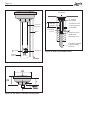
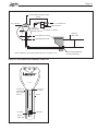
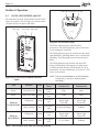
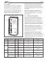
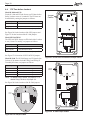
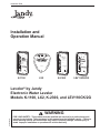
Installation Data Power Sensor Filling PWR II Installation and Operation Manual Power SENSOR FILL Sensor II Sensor I Filling 1 Power Sensor Filling Filling II Electronic Water Levelor Model No. K-2300 Model No. LEV110CK/2G The next genera tion in automated control s. SM Patented DO NOT OPEN NO USER SERVICEABLE PARTS INSIDE High Voltage Compartme nt No user servic e parts inside TM K-1100 LX2 K-2300 LEV110CK/2G Levolor® by Jandy Electronic Water Leveler Models K-1100, LX2, K-2300, and LEV110CK/2G H0303600B WARNING FOR YOUR SAFETY - This product must be installed and serviced by a professional pool/ spa service technician. The procedures in this manual must be followed exactly. Failure to follow warning notices and instructions may result in property damage, serious injury, or death. Improper installation or operation will void the warranty. Page 2 Page 3 Table of Contents Section 1.Safety Information....................... 4 Section 2.System Description..................... 5 2.1 Electrical Specifications................................5 2.2 Wiring Diagrams...........................................6 Section 3.Installation Instructions............ 10 3.1 3.2 3.3 3.4 3.5 3.6 3.7 Materials and Tools.....................................10 Installing the Control Box............................10 Changing Wiring for 110 Volt Operation .... 11 Grounding................................................... 11 Installing the Valve...................................... 11 Installing the Sensor...................................12 Installation Diagrams..................................13 Section 4. Operation...................................16 4.1 4.2 4.3 4.4 K-1100, LEV110CK/2G, and LX2................16 K-2300........................................................17 Fill Safety Lockout Mode............................17 Fill Time before Lockout.............................18 Section 5. Troubleshooting........................ 19 5.1 5.2 5.3 5.4 5.5 Manual Valve Override...............................19 Initial Observations at Job Site...................19 Test Operation of Control Unit....................19 Fill Will Not Turn OFF.................................20 Fill Will Not Turn ON...................................21 Section 6.Replacement Parts.................... 22 6.1 Ordering Information...................................22 Page 4 Section 1.Safety Information IMPORTANT SAFETY INSTRUCTIONS PERTAINING TO A RISK OF PROPERTY DAMAGE OR INJURY TO PERSONS READ AND FOLLOW ALL INSTRUCTIONS When installing and using this equipment, basic safety precautions should always be followed, including the following: WARNING FOR YOUR SAFETY. This product must be installed and serviced by a professional service technician, qualified in pool/spa installation and maintenance. Improper installation or operation could cause serious injury, property damage, or death. Improper installation or operation will void the warranty. WARNING Before installing this product, read and follow all warning notices and instructions accompanying them. Failure to follow safety warnings and instructions could result in severe injury, death, or property damage. WARNING To reduce the risk of injury, do not permit children to use this product unless they are closely supervised at all times. WARNING Risk of electric shock - Install the control box at least five (5) feet (152.4cm) from the inside wall of the pool and/ or hot tub using non-metallic plumbing. Canadian installations must be at least three (3) meters from the water. Children should not use spas or hot tubs without adult supervision. Do not use spas or hot tubs unless all suction guards are installed to prevent body and hair entrapment. People using medications and/or having an adverse medical history should consult a physician before using a spa or hot tub. WARNING To reduce the risk of electrical shock, connect the green ground wire marked to the ground of your electric service or supply panel with a continuous copper conductor having green insulation and one that is equivalent in size to the circuit conductors supplying this equipment, but no smaller than number 12 AWG (3.3mm). This ground wire marked is provided within the control box. Attention Installer: Install to provide drainage of compartment for electrical components. Attention Installer: This manual contains important information about the installation, operation and safe use of this product. This information should be given to the owner/operator of this equipment. SAVE THESE INSTRUCTIONS Page 5 Section 2.System Description Fill Line Levolor® Models K-1100, LEV110CK/2G, and LX2 are computer-controlled devices that detect a low water condition and automatically replace the water to a preset level. They can be used in all pools and spas. The LEV110CK/2G is designed for use in large commercial applications. Levolor II, Model K-2300, is a dual-fill device that can maintain the water level in two (2) separate environments, such as a pool/spa combination or other dual-equipped application. It can be used in any situation where a consistent liquid level is desired. The Levolor kit contains a sensor, a control box, and a solenoid valve. The Levolor II kit contains two (2) sensors, a control box, and two (2) solenoid valves. Figure 1. K-1100 or LEV110CK/2G Installation Fill Line Filter Check Valve For more details, see Section 3.1, Materials and Tools. Sensor Sensor Line inside Static Pipe There are three (3) styles of sensors: 1. Slip Style - installed in static pipe in new pool. 2. Skim Style - installed in skimmer in existing pool (also known as Half-moon Style). 3. Dual Style (Slip on one end/Skim on other end). NOTE An optional threaded sensor can be installed in a static pipe in a new pool. Depending on the model, the sensor comes with 50 to 500 feet of wire at the top and two (2) stainless steel contacts at the bottom. You can cut off the sensor wire you do not use. Control Box The control boxes for K-1100, LX2 and LEV110CK/2G have three (3) LED displays: Power, Sensor, and Filling. The control box for the K-2300 has five (5) LED displays: Power, Sensor I, Filling I, Sensor II, and Filling II. For more details, see Section 4. Operation. The K-1100, K-2300, and LEV110CK/2G are factory wired for 220 volt operation and require rewiring for 110 volt operation. The LX2 comes in a 220 volt unit and a 110 volt unit. Valve The K-1100, LX2, and LEV110CK/2G require one (1) valve, and the K-2300 requires two (2) valves. Control Box Pump Solenoid 1" Brass "Y" Strainer Water Source Return Line Figure 2. LX2 Installation The K-1100, LX2, and K-2300 use a 1" valve (Part # SOL100). It has a pressure rating that cannot exceed 125 PSI. The LEV110CK/2G uses a 2" valve (Part # SOL200). It has a pressure rating that cannot exceed 150 PSI. 2.1 Electrical Specifications Models K-1100, LX2, K-2300, and LEV110CK/2G Input: 110 VAC, 50/60 HZ, 0.5 AMPS 220 VAC, 50/60 HZ, 0.5 AMPS Output:24 VAC@ 1 AMP CAUTION Models K-1100, K-2300, and LEV110CK/2G are factory wired for 220 VAC service. If available electrical service is 110 VAC, the power supply wiring must be changed to operate on 110 VAC as shown in figures 4, and 5. Page 6 2.2 Wiring Diagrams This section contains wiring diagrams for the K-1100, K-2300, and LEV110CK/2G, along with detailed views of the factory-direct wiring for 220 VAC and the modified wiring for 110 VAC. The section also contains a wiring diagram for the LX2, along with detailed views of the factory-direct wiring for the 220 VAC and 110 VAC units. Three (3) Status Lights Blue Wires Orange Wires Transformer Green Wire (Ground) Black Wire Black Wire/White Stripe Black Wire/Red Stripe Black Wire/Yellow Stripe See Figure 4 for factory-direct wiring for 220 volt operation and Figure 5 for modified wiring for 110 volt operation. Sensor Wires (Orange Wires) Solenoid Valve Wires (Blue Wires) Sensor Figure 3. K-1100 and LEV110CK/2G Control Box Page 7 220 Volt Operation Transformer BLK/YEL BLK/WHT BLK Green Ground 1 2 BLK/RED 5 6 Line 2 Line 1 Figure 4. K-1100, K-2300, and LEV110CK/2G Factory Wiring for 220 Volt Operation 110 Volt Operation Transformer Ground Line 1 BLK/YEL 2 BLK/RED 5 BLK/WHT BLK Green 6 Neutral Figure 5. K-1100, K-2300, and LEV110CK/2G Modified Wiring for 110 Volt Operation Page 8 Front Inside View Back Inside View PCB 24 VAC S1 A Connect to Blue Solenoid Valve Wires Connect to Orange Sensor Wires Transformer Case B Transformer Enclosure Black Black Green Blue Wires to Solenoid Valve High Power ½" Conduit Valve ½" Conduit Orange Wires to Sensor Power Connect to Solenoid Using Grease-Filled Wire Nuts Black Green (Ground) Black 220 VAC or White 110 VAC Black See Figure 7 for factorydirect wiring for 220 volt operation and Figure 8 for factory-direct wiring for 110 volt operation. Line 1 Ground Line 2 Figure 7. LX2 Factory Direct Wiring for 220 Volt Unit White White Green Terminal Bar Black Black Green Black Terminal Bar Green Black Black Green Black Figure 6. LX2 Control Box Line Ground Neutral Figure 8. LX2 Factory Direct Wiring for 110 Volt Unit Page 9 Five (5) Status Lights Red Wires to Filling Valve II Blue Wires to Filling Valve I Black Wire to Power (24 VAC) Yellow Wire with Red Stripe to Sensor II Yellow Wire to Sensor Common Yellow Wire with Blue Stripe to Sensor I Black Wire to Power (24 VAC) Transformer Green Wire (Ground) Black Wire Black Wire/White Stripe Black Wire/Red Stripe Black Wire/Yellow Stripe Sensor I (Yellow Wire with Blue Stripe) See Figure 4 for factory-direct wiring for 220 volt operation and Figure 5 for modified wiring for 110 volt operation. Sensor Common (Yellow Wire) Sensor II (Yellow Wire with Red Stripe) Filling Valve I (Blue Wires) Filling Valve II (Red Wires) Figure 9. K-2300 Control Box Sensor I Sensor II Page 10 Section 3.Installation Instructions 3.1 Materials and Tools Installation Materials Supplied for Levolor® Models K-1100, LX2, or LEV110CK/2G Qty Sensor with Wire 1 Solenoid Valve 1 Coupler 1 Control Box 1 Remote Sensor Housing 1 Hardware Kit 1 Installing the Control Box NOTE When installing a Levolor on a spa (less than 300 sq ft of surface area), turn the flow control down to reduce the flow rate of the valve. Models K-1100, K-2300, and LEV110CK/2G Grease-Filled Wire Nuts for Valve 2 per kit Screws 4 per kit Anchors 4 per kit Owner’s Manual - Warranty Information 1 Installation Materials Furnished for Levolor II, Model K-2300 Qty Sensor with Wire 2 Solenoid Valve 2 Coupler 2 Control Box 1 Remote Sensor Housing 2 Hardware Kit 2 Grease-Filled Wire Nuts for Valve 2 per kit Screws 4 per kit Anchors 4 per kit Owner’s Manual - Warranty Information 3.2 1 Additional Materials Needed for Installation Anti-siphon Valve* 2-Conductor, 18-Gauge Solid-Core Burial Cable Wire Nut Connectors for the Sensor and Power Connections *The anti-siphon valve is not necessary if the connection is made from the irrigation system. Open the box and check to see that it contains the contents listed above. If it does not, contact your dealer or Zodiac technical support at (800) 822-7933. 1. Mount the control box to the wall near the pump and filter. See Figure 1. Do not install the control box within 10 ft (3 m) of the pool edges. 2. Mount the control box at eye level. Leave sufficient clearance on all sides of the chassis backplate. 3. Check the source voltage. (All three (3) units are factory wired for 220 volt operation.) To modify the wiring for 110 volt operation, see Section 3.3. 4. For 220 volt operation, connect the black wire to line 1 and connect the black wire with the yellow stripe to line 2. See Figure 4. Model LX2 1. Mount the control box in the static pipe where the sensor is installed. See Figure 2. 2. Check the source voltage. (There are separate units for 220 and 110 volt operation.) a. For 220 volt operation, connect one (1) of the black wires to line 1 and the other black wire to line 2. See Figure 7. b. For 110 volt operation, connect the white wire to the white neutral line. Then connect the black wire to the black power line. See Figure 8. Page 11 3.3 Changing Wiring for 110 Volt Operation WARNING Potentially high voltages in the Levolor® control box can create dangerous electrical hazards, possibly causing death, serious injury or property damage. Turn off power at the main circuit breaker providing power to the control box to disconnect the control box from the system. To properly and safely wire the system, be sure to carefully follow the applicable requirements of the National Electrical Code (NEC), NFPA 70 or the Canadian Electrical Code (CEC), CSA C22.1. All applicable local installation codes must also be adhered to. Models K-1100, K-2300, and LEV110CK/2G Refer to Figures 4 and 5 and do the following: 1. Cut the splice cap connecting the black/white and the black/red wires. See Figure 4. 2. Connect the black/red wire with the black wire and connect to the line side of power. See Figure 5. 3. Connect the black/white wire with the black/yellow wire and connect to the neutral side of power. See Figure 5. 3.4 1. Connect the 24 VAC water solenoid valve to the 18-gauge solid-core burial cable using the supplied grease-filled wire nuts. 2. Connect the other end according to the model being installed, using the following instructions: Models K-1100, LX2, and LEV110CK/2G: Connect the valve wires to the blue wires in the control box using wire nuts. Model K-2300: Connect the wires from Valve I to the blue wires in the control box using wire nuts. Connect the wires from Valve II to the red wires in the control box using wire nuts. 3. Turn the flow control knob (+) on the top of the valve (See Figure 10) to set the flow rate to your specifications. NOTE The rate can be set up to 30 GPM for the K-1100, LX2, and K-2300. The rate can be set up to 130 GPM for the LEV110CK/2G. 4. Put the manual ON/OFF lever, located just below the solenoid, in the OFF position, so it will only open with the electronic water Levolor. See Figure 11. Grounding Flow Control Connect the green ground wire marked to the ground of your electric service or supply panel with a continuous copper conductor that has green insulation and is equivalent in size to the circuit conductors supplying this equipment, but no smaller than no. 12 AWG (3.3mm). Refer to your local codes for the acceptable grounding wire gauge. 3.5 NOTE Installing the Valve Install the valve with the directional water flow arrow pointing in the appropriate direction. The directional water flow arrow is located on the inlet side of the valve. Figure 10. Valve Flow Controller ON Manual On/Off Lever OFF Manual On/Off Lever A 24 VAC solenoid valve will provide water from a supply line to the pool or spa. You can install the supply line either before or after the filter at the equipment pad or on a dedicated line back to the pool. The K-1100, LX2, and K-2300 use a 1" valve, and the LEV110CK/2G uses a 2" valve. In addition, Zodiac recommends an anti-siphon valve (to help prevent accidental draining of the pool), and an in-line strainer, which you can purchase from Zodiac. Manual Filling Figure 11. Manual Valve Lever Controlled Filling Page 12 3.6 Installing the Sensor NOTE If using a dual style sensor, cut off and discard the sensor you are not planning to use. See Figure 12. CAUTION Important Safety Instructions. Sensor wires must be continuous and not spliced. Solder all low voltage wire connections when possible and always use grease-filled wire nuts on low voltage connections. 1. Install the sensor in the appropriate location for the sensor style. a. Mount the skim (half-moon) sensor horizontally to an existing skimmer. Mount with velcro or a suitable adhesive in the skimmer throat behind the whir door arc. See Figures 13 and 15. b.Mount the slip sensor vertically in a static pipe. Glue the sensor to the coupling. See Figures 14 and 16. Skim Style Slip Style Figure 12. Dual Style Sensor SIDE VIEW Cable Do Not Submerge Sensor Under Water Sensor Existing Water Level TOP VIEW Mount Sensor with Velcro NOTE Screw the optional threaded sensor into a 1" threaded coupling. NOTE When using the static pipe method, glue all 1” fittings only. Do not glue 2” fittings. Glue all fittings with proper ABS/PVC glue: 793 IPS brand for ABS/PVC. 2. Connect the sensor wires as follows: Models K-1100, LX2, and LEV110CK/2G: Connect the sensor cable to the two (2) orange wires in the control box using wire nuts. See Figures 3 and 6. Model K-2300: a. Connect one (1) wire from Sensor I and one (1) wire from the Sensor II to the yellow Sensor Common wire using wire nuts. See Figure 9. b.Connect the other wire from Sensor I to the yellow wire with the blue stripe using wire nuts. See Figure 9. Sensor Cable Figure 13. Skim (Half-moon) Sensor Retrofit Installation SIDE VIEW Cable Extension Pipe Do Not Submerge Sensor Under Water Coupling Sensor Tips Sensor Water Level TOP VIEW c. Connect the other wire from Sensor II to the yellow wire with the red stripe using wire nuts. See Figure 9. NOTE For all models, the wire to the sensors must be continuous. There cannot be any wire splices. Sensor Cable Figure 14. Slip Sensor Installation Page 13 Anti-siphon Valve Sensor Probes House or Irrigation System Levolor® Control Box Check Valve Return to Pool Figure 15. Skim (Half-moon) Sensor in Skimmer Installation in Exisiting Pool 3.7 Installation Diagrams This section shows diagrams of skim (half-moon) style and slip style sensor installations and details. They are: - Skim (Half-moon) Sensor in Skimmer Installation in Existing Pool - Slip Sensor in Static Pipe Installation in New Pool - Slip Sensor Detail - Slip Sensor in Remote Housing Detail - Deck Lid Installation Detail - LX2 Static Pipe Installation in New Pool - Slip Sensor in LX2 Installation Detail Levolor® K-1100 or LEV110CK/2G 110-220 VAC 24 VAC From City Water Supply via DBL CHK VLV 1 ½" to Return Line Solenoid Valve 1" Brass "Y" Strainer Equip Room Floor Level Operating Water Level 1' - 0" Operating Water Level 2" Stilling Line NOTE Install Line Level or Run Up-Hill From Pool to Prevent Air Lock Figure 16. Slip Sensor in Static Pipe Installation in New Pool Grate Covered Wall Fitting or ½" Eye-Ball Fitting Page 14 9" Deck Lid ½" Conduit Connection PVC Cut To Length PVC 6" 1" PVC Cut to Length 1" Coupling Sensor Conduit to Sensor Control System at Control Box Terminate Sensor at Minimum Operating Level 2" Static Line Vented at Top by Drilling Hole in It Coupling Slip Sensor Desired Water Level Figure 17. Slip Sensor Detail Figure 18. Slip Sensor in Remote Housing Detail Figure 19. Deck Lid Installation Detail Page 15 Levolor® Electronic Water Leveler 24 VAC 1 ½" to Return Line 110 / 220 VAC Water Level Controller DO NOT OPEN 6" MIN. NO USER SERVICEABLE PARTS INSIDE Solenoid Valve From City Water Supply Via DBL CHK VLV 1" Brass "Y" Strainer Equip Room Floor Level Operating Water Level MIN. 1' - 0" Operating Water Level 2" Stilling Line NOTE Install Line Level or Run Uphill From Pool to Prevent Air Lock Figure 20. LX2 in Static Pipe Installation in New Pool Water Level Controller DO NOT OPEN NO USER SERVICEABLE PARTS INSIDE 2" Static Line Vented Near Top by Drilling Hole in It 1" Coupling 1" PVC Cut to Length 2" PVC Slip Sensor Desired Water Level Figure 21. Slip Sensor in LX2 Installation Detail Grate Covered Wall Fitting or 1/2" Eye-Ball Fitting Page 16 Section 4. Operation 4.1 Power Light Sensor Light Fill Light K-1100, LEV110CK/2G, and LX2 The controllers for the K-1100 and LEV110CK/2G (See Figure 22) and the LX2 (See Figure 23) each have three (3) lights. Refer to the figures and Table 1. Power Light PWR SENSOR FILL Sensor Light Filling Light DO NOT OPEN NO USER SERVICEABLE PARTS Power Sensor INSIDE Figure 23. LX2 Controller Lights Filling The Power light turns green when the unit is powered on. The Sensor light turns yellow when water is not touching the sensor tips. The Filling light turns green 20 seconds after the sensor light illuminates, indicating that the valve is operational and filling. The Filling light turns off when the pool is filled. The Filling light turns red when the unit enters Fill Safety Lockout Mode. This happens if it takes longer to fill the pool than the time period allotted (20, 40, or 60 minutes). For more information, see Section 4.3, Fill Safety Lockout Mode. Figure 22. K-1100 and LEV110CK/2G Controller Lights Delay to Turn Function ON Delay to Turn Function OFF None None None None Fill Valve is ON 20 Seconds after Sensor Light Turns ON 20 Seconds after Sensor Light Turns OFF Red Fill Valve is OFF 20, 40 or 60 Minutes 24 Hours Filling Pool Green Fill Valve is ON 20 Seconds after Sensor Light Turns ON 20 Seconds after Sensor Light Turns OFF Safety Lockout Red Fill Valve is OFF 1, 2, or 3 Hours 24 Hours LED Function Color Power Turn Power ON Green Sensor Detect Low Water Yellow Filling Pool Green Safety Lockout Filling for K-1100 and LX2 Filling for LEV110CK/2G NOTE The time period allotted for the LEV110CK/2G to fill is one (1), two (2), or three (3) hours. See Table 1. Operating Mode Power is ON Water is Low Table 1. LED Indicators for K-1100, LX2, and LEV110CK/2G Page 17 4.2 K-2300 The controller for the K-2300 has five (5) lights. See Figure 24 and refer to Table 2. The Power light turns green when the unit is on. The Sensor I light turns yellow when water is not touching the Sensor I tips. Twenty seconds later, the Filling I light turns green, indicating that Valve I is operational and filling. The light turns off when the pool is filled, and turns red when Valve I goes into Safety Lockout Mode. Sensor II Sensor I II Power Power Sensor I Sensor II Filling I Filling II Electronic Water Levelor Model No. K-2300 The next generat ion in automated con trols . SM High Voltage Compartment No user servic e parts inside The Fill Safety Lock-out Mode shuts the Filling I or Filling II valve down for 24 hours or until the unit is powered down and back up to reset the filling time. When the unit goes into lock-out, it indicates a possible problem with the control, sensor, or water fill line system. The 24-hour window provides time to find and fix the problem. If the problem has not been fixed after 24 hours, the control will lock out for another 24 hours. The pre-set factory Fill time for the K-1100, LX2, and K-2300 is 20 minutes, but it can be modified to 40 or 60 minutes. The pre-set factory Fill time for the LEV110CK/2G is one (1) hour, but it can be modified to two (2) or three (3) hours. See Table 1 for pre-set and modified Fill times. See Section 4.4 for instructions on modifying pre-set Fill times. TM Figure 24. K-2300 Controller Lights Delay to Turn Function ON Delay to Turn Function OFF None None None None 20 Seconds after Sensor Light Turns ON 20 Seconds after Sensor Light Turns OFF Fill I Valve is OFF 20, 40 or 60 Minutes 24 Hours Yellow Water in Spa is Low None None Filling Spa Green Fill II Valve is ON 20 Seconds after Sensor Light Turns ON 20 Seconds after Sensor Light Turns OFF Safety Lockout Red Fill II Valve is OFF 20, 40 or 60 Minutes 24 Hours LED Function Color Power Turn Power ON Green Sensor I Detect Low Water in Pool Yellow Filling Pool Green Safety Lockout Red Detect Low Water in Spa Sensor II Fill Safety Lockout Mode All four (4) models described in this manual are equipped with a lock-out sequence. This means that if the Levolor® sensor has not been touched by water within the pre-set Fill time period, the controller turns the valve off for 24 hours and changes the Filling I or Filling II light from green to red. Patented Filling I Note that the K-2300 has two (2) Safety Lockout features, one (1) for Valve I and the other for Valve II. They operate independently. If one valve goes into Safety Lockout Mode, the other valve can continue to operate normally. 4.3 Filling II Filling I The Sensor II light turns yellow when water is not touching the Sensor II tips. Twenty seconds later, the Filling II light turns green, indicating that Valve II is operational and filling. The light turns off when the spa is filled, and it turns red when Valve II goes into Safety Lockout Mode. Filling II Table 2. LED Indicators for K-2300 Operating Mode Power is ON Water in Pool is Low Fill I Valve is ON Page 18 4.4 Fill Time before Lockout Model K-1100 and LX2: For the K-1100 and LX2 the factory-set Fill time before Safety Lockout occurs is 20 minutes. The Fill time can be modified by cutting the jumpers as follows: Cut Jumper Fill Time Period Either A or B 40 minute fill before lockout Both A and B 60 minute fill before lockout Jumper Cables S1 A B NOTE To disable the lockout feature, cut jumper S-1. See Figure 26 for the location of the LX2 jumpers and Figure 27 for the location of the K-1100 jumpers. Model LEV110CK/2G: The LEV110CK/2G factory-set Fill time before Lockout is one (1) hour. To modify, cut jumpers as follows: Cut Jumper Fill Time Period Either A or B 2 hours fill before lockout Both A and B 3 hours fill before lockout NOTE To disable the lockout feature, cut jumper S-1. See Figure 27 for location of LEV110CK/2G jumpers. Model K-2300: The K-2300 factory-set Fill time before Lockout is 20 minutes for both Filling I and Filling II. To modify fill times, cut jumpers as follows: Cut Jumper Fill Time Period Either A or B 40 minute fill before Filling I lockout Both A and B 60 minute fill before Filling I lockout Either C or D 40 minute fill before Filling II lockout Both C and D 60 minute fill before Filling II lockout Figure 27. K-1100 and LEV110CK/2G Jumper Cables S1 Jumper Cables A B S2 C D NOTE To disable Filling I lockout, cut jumper S-1. To disable Filling II lockout, cut jumper S-2. See Figure 28 for the location of the K-2300 jumpers. PCB Jumper Cables S1 A B Transformer Enclosure Figure 28. K-2300 Jumper Cables Figure 26. LX2 Jumper Cables Page 19 Section 5. Troubleshooting 5.1 Manual Valve Override There is a manual ON/OFF lever located just below the solenoid. If you are having a problem with the system and want to override the electronic water Levolor®, you can manually open the valve by putting the lever in the ON position. See Figure 11. During normal operation, the lever must be in the OFF position. 5.2 1. Proper wire usage between the controller and the valve. (Burial-style polypropelene-jacketed solidcore wire, at least 18-gauge.) (Same wire as the sensor wire.) 2. Proper wire nuts at the valve connection. (Greasefilled wire nuts or gel caps. Conventional wire nuts filled with silicone will not work since some silicones have acids that degrade copper wires.) 3. Sensor wire must be continuous and not spliced. (No splices between the tips and the controller.) 4. Proper use of appropriate sensor. (Slip style for static pipes or skim (half-moon) style for skimmer mounts where there is no water in transit from fountains, etc.) 5.3 Restore power to the control box and observe the operation. The control box is working if steps 5 - 9 occur. 5. The Power light turns green. 6. The Sensor light(s) turn yellow. 7. Send voltage to the valve(s). a. Models K-1100, LX2, and LEV110CK/2G: Twenty seconds after the Sensor light turns yellow, the Filling light turns green, sending 24VAC to the valve on the blue wires. b.Model K-2300: Twenty seconds after the Sensor I light turns yellow, the Filling I light turns green, sending 24 VAC to Valve I on the blue wires. Twenty seconds after the Sensor II light turns yellow, the Filling II light turns green, sending 24 VAC to Valve II on the red wires. c. Use a volt meter to confirm 24 VAC at wires in the control box. 8. Connect sensor wires: a. Models K-1100, LX2, and LEV110CK/2G: Connect the orange wires in the control box together and the yellow Sensor light turns off immediately. Twenty seconds later the green Filling light will turn off. b.Model K-2300: Connect the yellow wire with the blue stripe for Sensor I and the yellow common wire together in the control box, and the yellow Sensor I light turns off immediately. Twenty seconds later, the green Filling I light turns off. Connect the yellow wire with the red stripe for Sensor II and the yellow common wire in the control box. The Sensor II light turns off immediately. Twenty seconds later the Filling II light turns off. 9. After the green Filling light(s) turn off, use an AC voltmeter to confirm the following: a. Models K-1100, LX2, and LEV110CK/2G: 0 voltage at the blue wires in the control box. b.Model K-2300: 0 voltage at the blue wires for Valve I and the red wires for Valve II. Test Operation of Control Unit Shut power off to the control box. 2. Disconnect the sensor from the sensor wires: a. Models K-1100, LX2, and LEV110CK/2G: Disconnect the sensor from the orange wires in the control box. b.Model K-2300: Disconnect Sensor I from the yellow wire with the blue stripe and the yellow common wire in the control box. Disconnect Sensor II from the yellow wire with the red stripe and the yellow common wire in the control box. 4. Proper power input voltage to the box. 1. 3. b.Model K-2300: Disconnect Valve I from the blue wires in the control box and disconnect Valve II from the red wires in the control box. Initial Observations at Job Site When called to a job site, make these initial observations. 5. Disconnect the valve from the valve wires, making sure they do not touch each other or the power ground. a. Models K-1100, LX2, and LEV110CK/2G: Disconnect the valve from the blue wires in the control box. Use the troubleshooting flow charts on the following pages to find and fix specific problems. Page 20 5.4 Fill Will Not Turn OFF This is a troubleshooting flow chart for the K-1100, LX2, and LEV110CK/2G. Use it when the Fill function will not turn off. Fill Will Not Turn OFF Is fill light green or red? YES Is fill light on? NO RED GREEN Pull sensor out of water. Disconnect blue valve wires from control box. Does green NO fill light turn off? YES Possible Issues: 1. Needs greased-filled wire nut at valve. 2. Needs proper wire between controller and valve: solidcore 18-gauge wire with poly-pro jacket. 3. Valve is bad. Lockout sequence has taken effect. Call technical support at (707) 776-8200 ext. 260. Possible Issues: 1. Manual lever on valve needs to be turned off. 2. Valve is dirty: take valve apart and clean inside. 3. Diaphram is torn. 4. LED light needs to be aligned with lens cover. Place sensor back in water. Does sensor light turn off? NO YES Disconnect orange sensor wires from control box and touch them together. Wait 20 seconds. Does green fill light turn off? NO YES Possible Issues: 1. Needs greased-filled wire nut at valve. 2. Needs proper wire between controller and valve: solid-core 18-gauge wire with poly-pro jacket. 3. Valve is bad. Does green fill light turn off? NO PCB board is bad. YES Sensor is bad. Page 21 5.5 Fill Will Not Turn ON This is a troubleshooting flow chart for models K-1100, LX2, and LEV110CK/2G. Use it when the Fill function will not turn on. Fill Will Not Turn ON Lockout sequence has taken effect. Call technical support (707) 776-8200 ext 260. Is power light on? NO Transformer is bad. Pull sensor out of water. YES NO Does sensor light turn on? YES Disconnect orange sensor wires at control box. Wait 20 seconds. NO Does sensor light turn on? Is fill light red? NO Disconnect blue valve wires from control box. Does green fill light turn on? Does unit have power? YES YES YES NO YES Sensor is bad. NO Does green fill light turn on? YES NO Check blue wires with AC voltmeter. Is there 24 VAC? YES No power. Less power. Check for power at valve connection. Is there power? NO PBC board is bad. Verify correct input voltage to unit. Cable connection between valve and controller is bad. YES Valve is bad. NO Turn on power. Page 22 Section 6.Replacement Parts 6.1 Ordering Information To order or purchase parts for the Levolor® products, contact your nearest Jandy dealer or distributor. See the Jandy website at www.jandy.com for the nearest service center. For further assistance, contact Customer Service at Zodiac Pool Systems, Inc. at (800)-822-7933. NOTE To order the correct part, you need to supply the correct model number and part number. Key Description Model No. Part No. PCBs and Controllers 1 Levolor PCB with time-out system K-1100 LEVBRD (timeout) 2 Controller Only, Lev-220V K-1100 LEV220Control 3 PCB w/ Transformer, Lev-220V K-1100 LEV220BDw/TRANS 4 Controller Only, LX2, 110V and 220V LX2 LX2Control 5 PCB Only, LX2, 110V and 220V LX2 LX2Board 6 Controller Only, K-2300 220V K-2300 K2300220Control 7 PCB w/Transformer, K-2300 220V K-2300 K2300220BDT Slip Style Sensor (Static Pipe Install) 8 Slip Style 2 Contact Sensor w/20 ft K-1100, K-2300 S2040 8* Slip Style 2 Contact Sensor w/50 ft K-1100, K-2300 S2040A 8 Slip Style 2 Contact Sensor w/100 ft K-1100, K-2300 S2040C 8 Slip Style 2 Contact Sensor w/150 ft K-1100, K-2300 S2040E 8 Slip Style 2 Contact Sensor w/200 ft K-1100, K-2300 S2040G 8 Slip Style 2 Contact Sensor w/250 ft K-1100, K-2300 S2040I 8 Slip Style 2 Contact Sensor w/300 ft K-1100, K-2300 S2040K 8 Slip Style 2 Contact Sensor w/350 ft K-1100, K-2300 S2040M Threaded Style (Static Pipe Install) 9 Threaded Style 2 Contact w/50 ft K-1100, K-2300 S2042A 9 Threaded Style 2 Contact w/100 ft K-1100, K-2300 S2042C 9 Threaded Style 2 Contact w/200 ft K-1100, K-2300 S2042G 9 Threaded Style 2 Contact w/50 ft - 30” Sensor K-1100, K-2300 S2042A30 10 Half Moon Style 2 Contact w/ no wire K-1100, LX2, K-2300 S2044 10 Half Moon Style 2 Contact w/50 ft K-1100, LX2, K-2300 S2044A 10 Half Moon Style 2 Contact w/100 ft K-1100, LX2, K-2300 S2044C 10 Half Moon Style 2 Contact w/100 ft - 4” Sensor K-1100, LX2, K-2300 S2044C4 10 Half Moon Style 2 Contact w/150 ft K-1100, LX2, K-2300 S2044E 10 Half Moon Style 2 Contact w/200 ft K-1100, LX2, K-2300 S2044G 10 Half Moon Style 2 Contact w/250 ft K-1100, LX2, K-2300 S2044I 10 Half Moon Style 2 Contact w/300 ft K-1100, LX2, K-2300 S2044K 10 Half Moon Style 2 Contact w/350 ft K-1100, LX2, K-2300 S2044M Skim (Half Moon) Style (Skimmer Install) Page 23 Key Description Model No. Order Part No. Dual Style (Skimmer or Static Pipe Install) 11 Dual Style Sensor w/50 ft K-1100, LX2, K-2300 S2046A 11 Dual Style Sensor w/100 ft K-1100, LX2, K-2300 S2046C 11 Dual Style Sensor w/150 ft K-1100, LX2, K-2300 S2046E 11 Dual Style Sensor w/200 ft K-1100, LX2, K-2300 S2046G 11 Dual Style Sensor w/250 ft K-1100, LX2, K-2300 S2046I 11 Dual Style Sensor w/300 ft K-1100, LX2, K-2300 S2046K 11 Dual Style Sensor w/350 ft K-1100, LX2, K-2300 S2046M 11 Dual Style Sensor w/400 ft K-1100, LX2, K-2300 S2046O 11 Dual Style Sensor w/450 ft K-1100, LX2, K-2300 S2046Q 11 Dual Style Sensor w/500 ft K-1100, LX2, K-2300 S2046S Miscellaneous 12 Remote Sensor Cover and Lower Housing K-1100, LX2, K-2300 70010110 13 1” Plastic Valve, 24 V Solenoid w/Flow Control K-1100, LX2, K-2300 SOL100 14 1” Y Strainer K-1100, LX2, K-2300 BRY Limited Warranty Zodiac Pool Systems, Inc. (“Zodiac”) warrants all Baracuda®, Jandy®, Nature2® and Polaris® brand products to be free from manufacturing defects in materials and workmanship for a period of one (1) year from the date of retail purchase, with the following exceptions: 1. Jandy heat pumps are warranted for two (2) years. Heat pump compressors and heat exchangers are warranted for ve (5) years. 2. Electronic salt water chlorine generators are warranted for three (3) years. 3. In-oor cleaning heads are warranted for the life of the pool on which they were originally installed, if originally installed with Zodiac’s in-oor cleaning valves. In-oor cleaning hydraulic valves, UltraFlex® 2 valve housings, and Leaf Trapper™ deck canisters are warranted for three (3) years. 4. Nature2 cartridges, except Spa sticks, CF cartridges, and Spring cartridges, are warranted for six (6) months. Spa sticks and CF cartridges are warranted for four (4) months. Spring cartridges are not warranted. Cense® is not warranted. 5. Baracuda X7 Quattro® and S3 cleaners are warranted for two (2) years. 6. Frames for Polaris ATV®, 280, 360, 380, 480 and 3900S cleaners are warranted for ve (5) years. 7. Kontiki cleaners are warranted for ninety (90) days. 8. Pool cleaner wear-and-tear items including, but not limited to, bags, tires, sweep hoses, sweep hose scrubbers, surface disks, aps, shoes, belts, rollers, scrubbers, and footpads, are not warranted. 9. Refrigerant and other expendables are not warranted. 10. Replacement products, or parts, provided at no charge are warranted only until the original nished good’s warranty has expired. Purchased replacement parts are warranted for ninety (90) days from the date of retail purchase. This warranty applies only to products purchased and utilized in the 50 United States and Canada, is limited to the rst retail purchaser, is not transferable, and does not apply to products that have been moved from their original installation sites. The liability of Zodiac shall not exceed the replacement of the defective product or its parts, and does not include transportation costs, costs for labor to service or repair the defective product, or any items or materials required to make the repair including, but not limited to, refrigerant and other expendables. Zodiac is not responsible for charges or delays incurred when a servicer is unable to perform service due to lock outs, animals, intolerable pool or spa water temperature when entry into pool or spa is required to perform service, service refusals, etc. No reimbursements will be made for loss and/or usage of water, fuel or other resources resulting from product defect. A third party service provider may charge the end-user customer for parts and/or labor required to resolve any issue not covered under warranty, such as improper installation. Zodiac is not responsible for these charges. Product discoloration, or any other cosmetic or supercial damage or deterioration, regardless of its cause, is not covered by this warranty. This warranty does not cover failures, defects, malfunctions or complaints resulting from any of the following: 1. Failure to properly install, operate or maintain the product in accordance with Zodiac’s published installation, operation and/or maintenance manuals. 2. The workmanship of any installer of the product. 3. Use of non-factory authorized parts or accessories in conjunction with the product(s). 4. Product modications or adjustments that are not in accordance with Zodiac’s published installation, operation and/or maintenance manuals. 5. Not maintaining proper pool and/or spa chemical balance [pH levels between 7.2 and 7.8, with ideal range being between 7.4 and 7.6; Total Alkalinity (TA) between 80 to 120 ppm; Total Dissolved Solids (TDS) less than 2000, not including salt ppm]. 6. Corrosion, erosion, scaling, calcication or other conditions caused by water hardness, chemical imbalance, or lack of product maintenance. 7. Chemical contamination of combustion air; or improper use of pool/spa chemicals, such as introducing chemicals upstream of the heater or cleaner hose, or through the skimmer; or use of copper-based algaecides in conjunction with Nature2 products. 8. Abuse, damage during transit or installation, mis-handling, tampering, vandalism, alterations, accidents, res, oods, storms, earthquakes, power surges, lightning, pets or other animals, insects and/or their hives or nests, negligence, or acts of God. 9. Not grounding and/or bonding as specied, mis-wiring, loose wiring, cut or kinked wires, loose cable connections, incorrect wire runs, incorrect breaker size, breaker(s) in “off” position, improper wire gauge, moisture in electrical conduit, improper electrical supply, dead batteries, incorrect plumbing, inadequate size of pipe and/or ttings, cross-threading, over-tightening, under-tightening, glue drips or residue, improperly secured covers, improper valve placement or usage, unsynchronized valve actuators, valve actuators in “off” position, improper gas pipe sizing, lack of fuel, inadequate heater vent pipe sizing, programming errors, or removal of in-line lter screens from pool cleaners. 10. Freezing, corrosion, cracking, overheating, warping, ooding, moisture intrusion or any other condition caused by or related to weather, climate, improper winterization, improper equipment placement, inadequate ventilation, inadequate water circulation, roof run-off, sprinklers, irrigation systems, or lights or other products on or near the pool/spa or pool/spa equipment pad. 11. Operating the product at water ow rates below minimum, or above maximum, specications. Operating any product or piece of equipment including, but not limited to, pumps, with insufcient quantities of water. 12. Improper equipment sizing, or product mis-applications including, but not limited to, unsuitable application of a pool cleaner, or use of residential products on commercial applications. 13. Dirty, clogged, blocked, covered or obstructed plumbing, cleaner parts, chlorine generator cells or sensors, pump strainer baskets, pump impellers, heater orices (including blockage by spider webs), heater grills, doors, ue boxes, ue vents or ue collectors, lter elements, or lter breather tubes. 14. Collateral damage caused by failure of any component including O-rings, pump strainer baskets, DE grids, sand lter laterals, or cartridge elements. This is the only warranty given by Zodiac. No one is authorized to make any other warranties on behalf of Zodiac. IMPLIED WARRANTIES, INCLUDING THE IMPLIED WARRANTY OF MERCHANTABILITY AND THE IMPLIED WARRANTY OF FITNESS FOR A PARTICULAR PURPOSE, ARE LIMITED TO THE EXPRESS WARRANTIES LISTED ABOVE. Some states and/or provinces do not allow limitations on how long an implied warranty lasts, so the above limitation may not apply to you. Zodiac expressly disclaims and excludes any liability for consequential, incidental, indirect, or punitive damages for breach of any expressed or implied warranty. In no event shall Zodiac be liable for incidental or consequential damages of any nature, including damage to vinyl liners, plaster, aggregate-based pool surfaces, tile, stone, coping, xtures, skimmers or skimmer covers, plumbing, drains, equipment covers or shelters, landscaping, animals, plants, or dwellings. Some states and/or provinces do not allow the exclusion or limitation of incidental or consequential damages, so the above limitation may not apply to you. Certain vinyl liner patterns are particularly susceptible to rapid surface wear or pattern removal caused by objects coming into contact with the vinyl surface, including pool brushes, pool toys, oats, fountains, chlorine dispensers, and automatic pool cleaners. Some vinyl liner patterns can be seriously scratched or abraded by rubbing the surface with a pool brush. Ink from the pattern can also rub off during the installation process or when it comes into contact with objects in the pool. Zodiac is not responsible for, and this warranty does not cover, pattern removal, cuts, abrasions or markings on vinyl liners. H0303600B This warranty gives you specic legal rights. You may also have other rights that vary by state and/or province. For warranty consideration, contact the original dealer and provide the following information: proof of purchase, model number, serial number, date of retail purchase, and date of installation. The dealer will contact the factory to obtain instructions regarding the claim and to determine the location of the nearest independent service company. If the dealer is not available, you can locate an independent service company in your area by visiting www.baracuda.com, www.jandy.com, or www.polarispool.com, or by emailing our Technical Support department at [email protected], or by calling our Technical Support department at 800-822-7933. In Canada, call 888-647-4004. All returned parts must have a Returned Material Authorization number to be evaluated under the terms of this warranty. ETL LISTED CONFORMS TO UL STD 1563 CERTIFIED TO CAN/CSA C22.2 NO. 218.1 Zodiac Pool Systems, Inc. 6000 Condor Drive, Moorpark, CA, USA 93021 • 800-822-7933 FAX 877-327-1403 Litho in USA © 2009 Zodiac Pool Systems, Inc. 0809