1
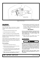
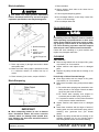
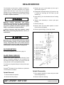
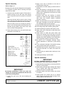
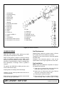
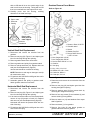
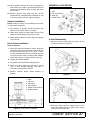
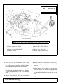
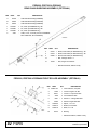
Fill Gearbox 2. Secure with carriage bolts (14) and flanged lock nuts (15). IMPORTANT ■ Gearbox is not filled at the factory. Prior to delivery, make sure each gearbox is filled half-full with 80W or 90W API GL-4 or GL-5 gear lube. 1. Make sure vent plug hole is clear. Fill gearbox halffull with high quality gear oil that has a viscosity index of 80W or 90W and an API service rating of GL-4 or GL-5. 2. Fill gearbox until oil runs out the side plug on gearbox. 3. Pour in one pint of gear lube, wait five minutes and add additional gear lube until it just comes out of side hole. 4. Allow an additional five minutes for the lube to flow through bearings, then check to make sure oil level is at bottom of side hole. Replace side plug. Install vent plug. Insert carriage bolts from bottom upward as shown. Install Front Roller (Optional) 1. Insert four carriage bolts (5) through the front mower frame from inside out. 2. Place roller bracket (8) over bolts; then install flange whiz nuts (6) on bolts and tighten. 3. Place front roller (9), two bearings (10), spacer (7) and two SAE flat washers (4) between roller bracket as shown in Figure 34. 4. Insert cap screw (3) through bracket and roller. 5. Secure with flanged lock nut (2). Do not overtighten, roller must spin freely. Install Chain Shielding (Optional) DANGER Full chain shielding, designed to reduce the possibility of thrown objects, must be installed when operating in populated areas or other areas where thrown objects could injure people or damage property. If this machine is not equipped with full chain shielding, operation must be stopped when anyone comes within several hundred feet. 2. 3. 4. 5. 6. 7. 8. 9. 10. 15 14 1/2 NC Flanged lock nut 1/2 NC Flanged lock nut 1/2 SAE Flat washer 3/8 NC x 1 Carriage bolt 3/8 NC Flanged whiz nut Spacer, .75 x 6.62 Bracket, front roller Roller, 4 x 7.37 Bearing 3 Figure 34. Front Roller Installation CM768 3. Shield, chain plate 14. Bolt, carriage 3/8 NC x 1 Install Quick Hitch Kit (Optional) NOTE: This kit allows mower to fit only Category 1 standard quick hitch. Figure 33. Chain Shield Installed 1. Make sure that you are using one of the front two attachment points (D) in the lower hitch plates. See Figure 6, page 12, for adjustment. 1. Install chain shielding plate (3) to rear mower frame as shown. 2. Remove clevis pins from lower hitch arms. The pins will not be used for the Quick Hitch. 15. Nut, flanged lock 3/8 NC MAN0475 (9/21/2005) Assembly 31