1
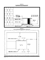
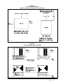
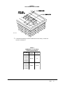
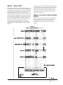
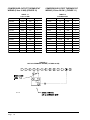
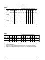
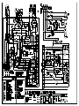
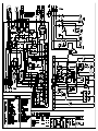
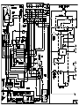
INSTALLATION INSTRUCTIONS
SINGLE PACKAGE
HEAT PUMPS
Models:
PH11242
PH12241
PH11301
PH1230
PH11361
PH1236
PH11422
PH1242
PH10481
PH11481
PH1060
Bard Manufacturing Company
Bryan, Ohio 43506
Since 1914 . . . Moving ahead, just as
planned.
Manual :
Supersedes:
File:
Date:
2100-354B
2100-354A
Volume II Tab 11
03-19-03
© Copyright 2003
CONTENTS
Getting Other Informations and Publications
General Instructions
Important ................................................................
Shipping Damage ....................................................
General ................................................................
Field-Installed Heater Packages (Optional) .............
2
2
2
2
Installation
Location ................................................................ 9
Typical Installations ................................................. 9
Condensate Drain Trap ......................................... 14
Air Filters .............................................................. 14
Wiring – Main Power ............................................. 15
Wiring – 24V Low Voltage Control Circuit ............. 15
Thermostats ........................................................... 16
Thermostat Indicator Lamps .................................. 17
Emergency Heat Position ...................................... 17
Transformer Taps ................................................... 17
Compressor Cutoff Thermostat and Outdoor
Thermostat Wiring ................................................. 17
Figures
Figure 1 Unit Dimensional Drawing ....................... 8
Figure 2 Slab Mounting at Ground Level ............ 10
Figure 3 Airflow and Service Access
Clearances ............................................ 10
Figure 4 Roof Top Application .............................. 11
Figure 5 Elevated Mounting Platforms ................. 11
Figure 6 Prefabricated Rood Curb
Specifications ........................................ 12
Figure 7 Field Fabricated Curbing ....................... 13
Figure 8 Condensate Drain Trap ......................... 14
Figure 9 Low Voltage Wiring ............................... 15
Figure 10 Unit 24V Terminal Board (5–10 KW) ..... 17
Figure 11 Unit 24V Terminal Board (15–20 KW) ... 18
Figure 12 Heat Pump Control Board ..................... 20
Figure 13 Fan Blade Setting ................................. 23
Figure 14 Brazing Diagram ................................... 24
Start Up and Operation
Three Phase Scroll Compressor Start Up
Information ............................................................. 19
Sequence of Operation .......................................... 19
Defrost Cycle ......................................................... 20
Troubleshooting
Solid State Heat Pump Control
Troubleshooting Procedure ...................................
Troubleshooting Guide ..........................................
Checking Temperature Sensor Check Out ............
Temperature vs. Resistance of
Temperature Sensor Chart ....................................
21
21
22
22
Service
Service Hints ......................................................... 23
Pressure Service Ports .......................................... 23
Refrigerant Charge ................................................ 23
Fan Blade Settings ................................................ 23
Suction and Discharge Tube Brazing .................... 24
Troubleshooting ECM Blower Motors ............ 25 & 26
Pressure Tables ................................................ 27-30
Tables
Table 1
Table 2
Table 2A
Table 2B
Table 3
Table 4
Table 5
Table 6
Table 7
Table 8
Table 9
Table 10
Table 11
Table 12
Table 13
Table 14
Table 15
Table 16
Table 17
Table 18
Table 19
Table 20
Table 21
Table 22
Table 23
Rated CFM and ESP .............................. 2
Electrical Data ......................................... 3
Electrical Data ......................................... 4
Electrical Data ......................................... 5
Optional Field Installed Heater
Packages ................................................ 6
Electric Heater Table ............................... 7
Dimensions of Unit .................................. 8
Roof Curb Dimensions .......................... 12
Thermostat Wire Size ........................... 13
Wall Thermostat and Subbase
Combinations .......................................... 9
Required Filters ..................................... 14
Thermostat Wire Size ........................... 16
Compressor Cutoff Thermostat
Wiring (5 - 10 KW) ............................... 18
Compressor Cutoff Thermostat
Wiring (15 - 20 KW) ............................. 18
Refrigerant Charge ............................... 23
Fan Blade Setting Dimensions .............. 23
Indoor Blower Performance .................. 24
Pressure Table - Cooling ....................... 27
Pressure Table - Heating ...................... 27
Pressure Table - Cooling ....................... 28
Pressure Table - Heating ...................... 28
Pressure Table - Cooling ....................... 29
Pressure Table - Heating ...................... 29
Pressure Table - Cooling ....................... 30
Pressure Table - Heating ...................... 30
Getting Other Information and Publications
These publications can help you install the air conditioner
or heat pump. You can usually find these at your local
library or purchase them directly from the publisher. Be
sure to consult current edition of each standard.
FOR MORE INFORMATION, CONTACT
THESE PUBLISHERS:
ACCA
Air Conditioning Contractors of America
1712 New Hampshire Ave. N.W.
Washington, DC 20009
Telephone: (202) 483-9370
Fax: (202) 234-4721
ANSI
American National Standards Institute
11 West Street, 13th Floor
New York, NY 10036
Telephone: (212) 642-4900
Fax: (212) 302-1286
National Electrical Code ........................... ANSI/NFPA 70
Standard for the Installation .................. ANSI/NFPA 90A
of Air Conditioning and
Ventilating Systems
Standard for Warm Air .......................... ANSI/NFPA 90B
Heating and Air
Conditioning Systems
Load Calculation for ............................... ACCA Manual J
Residential Winter and
Summer Air Conditioning
Duct Design for Residential ................... ACCA Manual D
Winter and Summer Air Conditioning
and Equipment Selection
ASHRAE American Society of Heating Refrigerating,
and Air Conditioning Engineers, Inc.
1791 Tullie Circle, N.E.
Atlanta, GA 30329-2305
Telephone: (404) 636-8400
Fax: (404) 321-5478
NFPA
National Fire Protection Association
Batterymarch Park
P.O. Box 9101
Quincy, MA 02269-9901
Telephone: (800) 344-3555
Fax: (617) 984-7057
Manual 2100-354
Page
1
GENERAL INSTRUCTIONS
IMPORTANT
The equipment covered in this manual is to be installed by
trained, experienced service and installation technicians.
Any heat pump is more critical of proper operating charge
and an adequate duct system than a straight air
conditioning unit. All duct work, supply and return ducts,
must be properly sized for the design air flow requirement
of the equipment. ACCA is an excellent guide to proper
sizing. All duct work or portions thereof not in the
conditioned space should be properly insulated in order to
both conserve energy and prevent condensation or
moisture damage.
SHIPPING DAMAGE
Upon receipt of equipment, the carton should be checked
for external signs of shipping damage. If damage is found,
the receiving party must contact the last carrier
immediately, preferably in writing, requesting inspection
by the carrier’s agent.
These instructions and any instructions packaged with any
separate equipment required to make up the entire heat
pump system should be carefully read before beginning the
installation. Note particularly “Starting Procedure” and
any tags and/or labels attached to the equipment.
While these instructions are intended as a general
recommended guide, they do not supersede any national
and/or local codes in any way. Authorities having
jurisdiction should be consulted before the installation is
made.
FIELD INSTALLED HEATER PACKAGES
(OPTIONAL)
These packaged heat pumps are manufactured without
supplementary electric heaters. Supplementary heaters are
available for simple, fast field installation.
A separate power circuit is required for the supplementary
heaters.
IMPORTANT: Refer to Table 1 when designing duct
work for maximum available static pressure with heater
installed.
GENERAL
The refrigerant system is completely assembled and
charged. All internal wiring is complete.
Refer to electrical data shown in Tables 3 and 4 for proper
application information on all available heater
combinations and what units they can be used with. It also
shows the applicable circuit ampacities, fuse size, and wire
size for each heater combination.
The unit is designed for use with or without duct work.
Flanges are provided for attaching the supply and return
ducts.
These instructions explain the recommended method to
install the air cooled self-contained unit and the electrical
wiring connections to the unit.
TABLE 1
RATED CFM AND EXTERNAL STATIC PRESSURE (ESP)
Model
Rated
C FM
Recommended
Airflow Range
Rated
ESP
Maximum
ESP
PH11242
800
680-880
0.20
0.50
PH12241
800
Note 1
0.10
0.50
PH11301
1000
775-1100
0.30
0.40
PH1230
1000
Note 1
0.15
0.50
PH11361
1000
775-1210
0.20
0.40
PH1236
1000
Note 1
0.15
0.50
PH11422
1400
1260-1540
0.20
0.35
PH1242
1400
Note 1
0.15
0.50
PH10481
1550
1400-1700
0.40
0.50
PH12481
1550
Note 1
0.20
0.50
PH1060
1700
1530-1870
0.20
0.50
NOTE: Motor will adjust to deliver rated airflow.
Manual 2100-354
Page
2
TABLE 2
ELECTRICAL DATA
Model
Electric Rating
60 H z - C kt A
PH11242
PH11301
PH11361
PH11361-B
230/208-60-1 230/208-60-1 230/208-60-1 230/208-60-3
Operating Votage Range
197-253
Minimum Circuit Ampacity
BC SC
PH11361-C
PH11422
460-60-3
230/208-60-1
197-253
197-253
197-253
187-253
414-506
17
21
25
18
12
29
11
13.5
18
11
6
18.5
Field Wire Size *
10
10
8
10
14
8
Ground Wire Size
10
10
10
10
14
10
Delay Fuse - Max. **
Total Unit Amps - 203-208
25
30
40
25
15
50
13.9/14.9
15.7/17.2
18.9/20.7
13.2/13.8
6.9
22.8/24.2
Scroll
Scroll
Scroll
Scroll
Scroll
Scroll
Compressor - Circuit A
Compressor Type
230/208
230/208
230/208
230/208
460
230/208
Rated Load Amps
Volts
10/11
11.5/13
14.7/16.5
9.0/9.6
4.7
17.1/18.5
Lock Roter Amps
54/54
72.5/72.5
88/88
77/77
39
104/104
1/5 - 1090
1/5 - 1075
1/5 - 1075
1/5 - 1075
1/5 - 1075
1/3 - 825
1.8
1.6
1.6
1.6
0.8
2.5
20"/1650
20"/2000
20"/2000
20"/2000
20"/2000
24"/2950
Fan Motor and Condenser
Fan Motor - HP/RPM
Fan Motor Amps
Fan Dia/CFM
Motor and Evaporator
1/3 - 1075
1/3 - 1075
1/3 - 1075
1/3 - 1075
1/3 - 1075
1/2 - 1075
Blower Motor - Amps
Blower Motor - HP/RPM
2.1
2.6
2.6
2.6
1.4
3.2
CFM Cooling & ESP
800 @ 0.20
1100 @ 0.30 1100 @ 0.20 1100 @ 0.20 1100 @ 0.20 1400 @ 0.20
Charge (R22 oz.)
88
93
86
86
86
121
Shipping Weight (pounds)
365
365
365
365
365
435
*
75 degree C copper wire
** Maximum time delay fuse of HACR type circuit breaker
Manual 2100-354
Page
3
TABLE 2A
ELECTRICAL DATA
Model
Electric Rating
60 H z - C kt A
P H 10481
PH10481-B
230/208-60-1 230/208-60-3
PH10481-C
460-60-3
P H 1060
PH1060-B
230/208-60-1 230/208-60-3
PH1060-C
460-60-3
Operating Votage Range
197-253
187-253
414-506
197-253
187-253
414-506
Minimum Circuit Ampacity
33
24
12
42
28
14
21.5
14.7
7.1
29
18
9
Field Wire Size *
BC SC
8
8
12
8
8
12
Ground Wire Size
10
10
10
10
10
12
Delay Fuse - Max. **
50
35
15
60
45
20
25.2/21.2
18.3/19.7
9
30.3/32.5
21.3/22.8
11
Scroll
Scroll
Scroll
Scroll
Scroll
Scroll
Volts
230/208
230/208
460
230/208
230/208
460
Rated Load Amps
19.5/21.5
12.6/14.0
6.2
24.6/26.8
15.6/17.1
8.2
Lock Roter Amps
137/137
91/91
50
148/148
137/137
62
1/3 - 850
1/3 - 850
1/3 - 850
1/3 - 850
1/3 - 850
1/3 - 850
Total Unit Amps - 203-208
Compressor - Circuit A
Compressor Type
Fan Motor and Condenser
Fan Motor - HP/RPM
Fan Motor Amps
2.5
2.5
1.2
2.5
2.5
1.2
24"/3000
24"/3000
24"/3000
24"/3000
24"/3000
24"/3000
1/2 - 1075
1/2 - 1075
1/2 - 1075
1/2 - 1075
1/2 - 1075
1/2 - 1075
Blower Motor - Amps
3.2
3.2
1.6
3.2
3.2
1.6
CFM Cooling & ESP
Fan Dia/CFM
Motor and Evaporator
Blower Motor - HP/RPM
1550 @ 0.40
1550 @ 0.40
1550 @ 0.40
1700 @ 0.20
1700 @ 0.20
1700 @ 0.20
Charge (R22 oz.)
125
125
125
157
157
157
Shipping Weight (pounds)
450
450
450
450
450
450
*
75 degree C copper wire
** Maximum time delay fuse of HACR type circuit breaker
Manual 2100-354
Page
4
TABLE 2B
ELECTRICAL DATA
Model
Electric Rating
60 H z - C kt A
P H 12241
P H 1230
P H 1236
PH1236-B
P H 1242
P H 12481
PH12481-B
230/208-60-1 230/208-60-1 230/208-60-1 230/208-60-3 230/208-60-1 230/208-60-1 230/208-60-3
Operating Votage Range
197-253
197-253
197-253
187-253
197-253
197-253
187-253
Minimum Circuit Ampacity
17
21
26
19
30
33
25.4
10.5
13.5
16.5
10.9
18
20.5
14.7
BC SC
Field Wire Size *
12
10
10
12
10
8
8
Ground Wire Size
10
10
10
10
10
10
10
Delay Fuse - Max. **
25
30
40
25
45
50
35
12.9/13.9
15.6/17.1
19.4/21.2
14.7/15.6
23.5/24.5
25.5/27.5
19.0/20.3
Scroll
Scroll
Scroll
Scroll
Scroll
Scroll
Scroll
Total Unit Amps - 203-208
Compressor - Circuit A
Compressor Type
Volts
230/208
230/208
230/208
230/208
230/208
230/208
230/208
Rated Load Amps
9.5/10.5
11.5/13.0
14.7/16.5
10/10.9
16.7/17.7
18.5/20.5
12.0/13.3
Lock Roter Amps
54/54
72.5/72.5
88/88
77/77
104/104
137/137
91/91
1/5 -1090
1/5 - 1075
1/5 - 1075
1/5 - 1075
1/3 - 825
1/3 - 825
1/3 - 825
1.2
1.4
1.4
1.4
2.5
2.5
2.5
20"/1650
20"/2000
20"/2000
20"/2000
24"/3000
24"/3000
24"/3000
1/3 Variable
1/2 Variabel
1/2 Variable
1/2 Variable
3/4 Variable
3/4 Variable
3/4 Variable
2.2
2.7
3.3
3.3
4.3
4.5
4.5
Fan Motor and Condenser
Fan Motor - HP/RPM
Fan Motor Amps
Fan Dia/CFM
Motor and Evaporator
Blower Motor - HP/RPM
Blower Motor - Amps
CFM Cooling & ESP
Charge (R22 oz.)
Shipping Weight (pounds)
*
800 @ 0.10 1000 @ 0.15 1000 @ 0.15 1000 @ 0.15 1400 @ 0.20 1550 @ 0.20 1550 @ 0.20
91
99
121
121
133
123
123
320
335
345
345
420
440
440
75 degree C copper wire
** Maximum time delay fuse of HACR type circuit breaker
Manual 2100-354
Page
5
Manual 2100-354
Page
6
TABLE 3
OPTIONAL FIELD INSTALLED HEATER PACKAGES
ONLY TO BE USED WITH THE HEAT PUMP MODELS INDICATED
Heater
P ackag e
Model
Volts and
P h ase
PH11242
P H 12241
PH11301
P H 1230
EH3PB-A05
240/208-1
S
NA
S
NA
EH3PB-A08
240/208-1
S
NA
S
NA
S
EH3PB-A10
240/208-1
NA
NA
S1
S
S1
EH3PB-A15
240/208-1
NA
NA
S
NA
S
EH3PC-A05
240/208-1
NA
S
NA
S
EH3PC-A10
240/208-1
NA
S
NA
EH3PC-A15
240/208-1
NA
NA
NA
PH11361 PH11361-B PH11361-C
P H 1236
PH1236-B
A
NA
NA
A
A
NA
NA
A1
A1
S
NA
A
A
NA
NA
NA
NA
NA
S
NA
NA
NA
NA
NA
NA
NA
S2
NA
NA
NA
S2
NA
S
A
EH3PB-B09
240/208-3
NA
NA
A1
NA
A1
S1
A1
NA
S
EH3PB-B15
240/208-3
NA
NA
A
NA
A
S
A
NA
S3
This column
has been left
blank
intentionally
EH3PB-C09
480-3
NA
NA
A1
NA
A1
A1
S1
NA
NA
EH3PB-C15
480-3
NA
NA
A
NA
A
A
S
NA
NA
Heater
P ackag e
Model
Volts and
P h ase
PH11422
P H 1242
P H 1060
PH1060-B
PH1060-C
EH5PB-A05
240/208-1
S
S
S
A
A
NA
S
A
A
PH10481 PH10481-B PH10481-C
PH12481 PH12481-B
S
EH5PB-A10
240/208-1
S1
S
S1
A1
A1
S
NA
S1
A1
A1
EH5PB-A15
240/208-1
S
S2
S
A
A
S2
NA
S
A
A
EH5PB-A20
240/208-1
NA
NA
S
A
A
NA
NA
S
A
A
EH5PB-B09
240/208-3
NA
NA
A1
S1
A1
NA
S
A1
S1
A1
EH5PB-B15
240/208-3
NA
NA
A
S
A
NA
S3
A
S
A
EH5PB-B18
240/208-3
NA
NA
A
S
A
NA
NA
A
S
A
EH5PC-C09
480-3
NA
NA
A1
A1
S1
NA
NA
A1
A1
S1
EH5PC-C18
480-3
NA
NA
A
A
S
NA
NA
A
A
S
S=Standard application – heater voltage and phase same as basic unit.
A=Alternate application – heater voltage and phase different from basic unit.
NA=Not approved.
j Max. KW that can operate with Heat Pump on.
k Max. KW that can operator with Heat Pump on is 10 KW. 15 KW will operate during
emergency heat.
l Max. KW that can operate with Heat Pump on is 9KW. 15 KW will operate during
emergency heat
TABLE 4
OPTIONAL FIELD INSTALLED ELECTRIC HEATER TABLE
Heater KW &
Capacity @
240 Volts
Heater Pkg. Unit Volts
Model No. & Phases
Heater KW &
Capacity @
208 Volts
Circuit B
KW
B TU H
KW
B TU H
240/208V
Heater
Amps
EH3PB-A05
EH3PB-A08
EH3PB-A10
EH3PB-A15
EH3PC-A08
EH3PC-A10
EH3PC-A15
240/208-1
240/208-1
240/208-1
240/208-1
240/208-1
240/208-1
240/208-1
5
8
10
15
5
10
15
17,100
27,300
34,100
51,200
17,100
34,100
51,200
3.75
6.00
7.50
11.25
3.75
7.50
11.25
12,800
20,500
26,000
38,400
12,800
26,000
38,400
20.8/18.1
33.3/28.8
41.6/36.2
62.5/54.1
20.8/18.1
41.6/36.2
62.5/54.1
EH5PB-A05
EH5PB-A10
EH5PB-A15
EH5PB-A20
240/208-1
240/208-1
240/208-1
240/208-1
5
10
15
20
17,100
34,100
51,200
68,200
3.75
7.50
11.25
15.00
12,800
26,000
38,400
51,200
20.8/18.1
41.6/36.2
62.5/54.1
83.2/72.1
EH3PB-B09
EH3PB-B15
240/208-3
240/208-3
9
15
30,700
51,200
6.75
11.25
23,000
38,400
EH5PB-B09
EH5PB-B15
EH5PB-B18
240/208-3
240/208-3
240/208-3
9
15
18
30,700
51,200
61,400
3.75
11.25
13.50
EH3PB-C09
EH3PB-C15
480-3
480-3
9
15
30,700
51,200
EH5PB-C09
EH5PB-C15
EH5PB-C18
480-3
480-3
480-3
9
15
18
30,700
51,200
61,400
Heater
Internal
F u se
1
N o.
Min.
Max. Over
Field
Circuit
Current
Circuits Ampacity Protection
2
Field
P o w er
Wiring
Ground
Wire Siz e
3
30/60
1
1
1
1
1
1
1
26/23
42/36
53/46
79/68
26/23
53/48
79/68
30/25
45/40
60/50
80/70
30/25
60/50
80/70
10/10
10/10
6/8
4/4
10/10
6/8
4/4
10
10
10
8
10
10
8
30/60
60/60
1
1
1
1
26/23
53/46
79/68
104/91
30/25
60/50
80/70
110/100
10/10
6/8
4/4
2/3
10
10
8
6
21.7/18.7
36.2/31.2
1
1
28/24
46/39
30/25
50/40
10/10
8/8
10
10
23,000
38,400
46,100
21.7/18.7
36.2/31.2
43.4/37.5
1
1
1
28/24
46/39
55/47
30/25
50/40
60/50
10/10
8/8
6/8
10
10
10
8.26
13.77
28,200
47,000
10.8
18.0
1
1
15
23
15
25
14
10
14
10
8.26
13.77
16.53
28,200
47,000
56,400
10.8
18.0
21.7
1
1
1
15
23
28
15
25
30
14
10
10
14
10
10
30/60
j Time delay fuses of HACR type circuit breakers must be used for 60 and smaller sizes. Standard fuses or circuit breakers are suitable for sizes 70 and
Manual 2100-354
Page
7
larger. 480V circuit breakers are not HACR type.
k Based on wire suitable for 75 degree C. Other wiring materials must be rated for marked Minimum Circuit Ampacity or greater.
l Based upon Table 250-95 of N.E.C. 1993. See electric data for basic heat pump for Circuit A wiring specification requirements.
NOTE:
While this electrical data is presented as a guide, it is important to electrically connect properly sized
fuses and conductor wires in accordance with the national Electrical Code and all existing local codes.
FIGURE 1
UNIT DIMENSIONAL DRAWING
MIS-1305
TABLE 5
DIMENSIONS OF UNIT
Duct Opening (Inches)
Model
N o.
Nominal Cabinet Dimensions (Inches)
A
B
C
J
PH1124
PH1224
PH1130
PH1230
PH1136
PH1236
24-1/4 48-3/16 38-1/8 26-1/8
PH1142
PH1242
PH1148
PH1248
PH1060
31-1/4
Manual 2100-354
Page
8
50
42
26
Discharge
Return Air
K
L
M
D
E
F
G
H
2-1/8
9/16
9/16
33
6
33
14
7/8
3
2-3/4
7-9/16
38
10
38
16
1-3/8
INSTALLATION
LOCATION
TYPICAL INSTALLATIONS
GENERAL
1. ROOF MOUNTED – The unit is mounted on a
sturdy base on the roof of the building. Return air to
the unit is brought through a single return grille (grilles
with built-in filters are best since they enable easy
access for filter changing). Return air ducts are
attached to the lower section of the front panel.
Supply air is brought from the unit to attic duct work
or to a furred down hall. Supply air duct is attached to
the top of the front panel.
The unit must be located outside, or in a well ventilated
area. It must not be in the space being heated or cooled. A
sound absorbing material should be considered if the unit
is to be installed in such a position or location that might
cause transmission of sound or vibration to the living area
or adjacent buildings.
SLAB MOUNTING
In areas where winter temperatures DO NOT go below
32° F for periods over twelve hours, the unit may be slab
mounted at grade level. When installing unit at grade
level, install on a concrete slab at least four inches above
finished grade level. Slab should have a slope tolerance
away from the building structure of at lease 1/4 inch per
foot, while being level from side to side. This will prevent
ice buildup under the unit during defrost cycles. Place slab
in a location where runoff water from higher ground will
not collect around unit. See Figure 2.
A minimum of 18 inches should be provided between the
coil inlet and any building surfaces. Provide at least four
feet between coil outlet and any building wall, fences or
other vertical structures. Provide a minimum of three feet
clearance on the service access side of the unit. See
Figure 3
ROOF MOUNTING
When a unit is installed in areas where low ambient
temperatures or strong winter winds exist, it should be
placed so prevailing winter winds are not in direct line
with the heat pump coil. If this is not possible, a wind
barrier should be constructed. Place barrier 24 inches
from the coil inlet side of the unit and in the direction of
prevailing winds. Size barrier at least the same height and
width as the unit. This may be necessary on ground level
installations, also. See Figure 4.
WINTER INSTALLATION BELOW 32°F
In areas where winter conditions go below 32°F for
extended periods, the unit must be elevated above the
mounting surface to prevent snowfall or defrost ice
accumulation from interfering with the operation of the
unit. A minimum of twelve inch elevation is
recommended, while greater elevation may be required for
areas of high snow accumulation. Poured concrete, steel
framework, brick, cement block, etc., can be utilized to
construct a suitable raised mounting platform. See
Figure 5.
CAUTION: All outdoor duct work must be
thoroughly insulated and weatherproofed. All
attic duct work must be thoroughly insulated.
Two inch thick insulation with suitable vapor
barrier is recommended for both outdoor and
attic runs.
In roof top installation, as in all installations, the heat
pump must be level from side to side. However, the
unit should have a pitch along the length to assure
complete external drainage of precipitation and of
defrost condensate. See Figures 6 and 7, and Tables 6
and 7.
2. CRAWL SPACE – Duct work installed in crawl
space must be well insulated and provided with a
vapor barrier. In addition, the crawl space must be
thoroughly ventilated and provided with a good vapor
barrier as a ground cover. It is most desirable to install
the unit outdoors rather than inside the crawl space, so
that it will be readily accessible for service. In
addition, it is necessary to dispose of the condensate
from the outdoor coil on the heating cycle, and this is
virtually impossible with the unit installed inside the
crawl space.
3. SLAB MOUNTED AT GROUND LEVEL – This
type installation is ideal for homes with a slab floor
construction where a roof mounted unit is not desired.
The supply and return duct work can be run through a
furred closet space.
4. THROUGH THE WALL – This type installation
requires a suitable framework to be fabricated capable
of withstanding the unit weight. Normally the unit will
be insulated so as to minimize supply and return duct
work.
Manual 2100-354
Page
9
FIGURE 2
SLAB MOUNTING AT GROUND LEVEL
(Above 32°F Outside Temperature)
FIGURE 3
AIRFLOW AND SERVICE ACCESS CLEARANCES
MIS-1185
Manual 2100-354
Page
10
FIGURE 4
ROOF TOP APPLICATION
(May also be required for ground level installations)
MIS-1176
FIGURE 5
ELEVATED MOUNTING PLATFORMS
MIS-1183
Manual 2100-354
Page
11
Manual 2100-354
Page
12
FIGURE 6
PREFABRICATED ROOF CURB SPECIFICATIONS
HEAVY GAUGE GALVANIZED WITH WOOD NAILING STRIP, WELDED/LEAKPROOF
ONE PIECE CONSTRUCTION – READY TO INSTALL
MIS-1177C
TABLE 6
ROOF CURB DIMENSIONS
R oof
H ood
Unit Model Model
R oof
Curb
Model
Roof Curb Details
A
F
G
38.375 35.375
42
24.25
RHE-60 9042-004 82.375 44.125 41.125 38.375 35.375
44
31.25
PH1124*
PH1224*
PH1130*
PH1230*
PH1136*
PH1236*
RHE-36 9042-003 80.375
PH1142*
PH1242*
PH1048*
PH1248*
PH1060*
*
Revision Level
B
C
40.25
37.25
D
E
H
I
J
K
L
19.125 48.188
14.75
38.125
38.25
19.125
14.75
42
38.25
50
FIGURE 7
FIELD FABRICATED CURBING
MIS-1178A
j
A separate metal flashing should be installed around wood curbing. Caulk & seal
all joints & weatherproof.
TABLE 7
DIMENSION “X” FOR FIELD
FABRICATED CURBING
Unit Model
Roof Hood Dimension
Model
X
PH1124
PH1224
PH1130
PH1230
PH1136
PH1236
RHE-36
41
PH1142
PH1242
PH1048
PH1248
PH1060
RHE60
44-7/8
Manual 2100-354
Page
13
5. OTHER INSTALLATIONS – Many other
installations are possible with the packaged heat pump.
No matter what the installation, always consider the
following facts:
A. Insure that the discharge air is not obstructed inany
way so as to cause operation difficulties.
B. The indoor coil drain pan is equipped with a
coupling that must be piped through a condensate
drain trap to a suitable drain.
C. Always mount the unit is such a position that it
may be easily reached for servicing and
maintenance.
D. Insure that the unit is clear so that proper air flow
over the outdoor coil will be maintained.
If this unit is operated in cooling below a 65° outdoor
ambient temperature, the installation of low ambient
controls (CMA-6) to unit is required.
AIR FILTERS
Air filters for the return air side of the system are not
provided as part of the various types of applications for
these models, and must be field supplied and installed as
part of the final installation.
Prior thought should be given to return air location and
placement of the air filter(s). The air filter(s) must be of
adequate size and readily accessible to the operator of the
equipment. Filters must be adequate in size and properly
maintained for proper operation. If this is not done,
excessive energy use, poor performance, and multiple
service problems will result. It is impossible to oversize
air filters. Generous sizing will result in cleaner air and
coils as well as lower operating costs and extend the time
between required changes. Table 8 shows minimum filter
areas and recommended filter sizes. Actual filter sizes can
vary with the installation due to single or multiple returns
utilizing a filter/grille arrangement or being placed
immediately ahead of the indoor coil face in the return air
duct.
CONDENSATE DRAIN TRAP
It is very important to provide a trap in the condensate
drain line to allow a positive liquid seal in the line and
assure correct drainage from the coil condensate pan.
Install condensate drain trap shown in Figure 8. Use drain
connection size or larger. Do not operate unit without
trap. Unit must be level or slightly inclined toward drain.
With a trap installed on a unit located in an unconditioned
area, water in the trap may freeze. It is recommended that
the trap material be of a type that will allow for expansion
of water when it freezes.
TABLE 8
FILTERS REQUIRED AND SIZE
Model No.
Minimum Filter Area
Recommended
Siz e
PH1124
PH1224
PH1130
PH1230
PH1136
PH1236
462 Square Inches
(3.21 Square Feet)
15 x 30-5/8 x 1
PH1142
PH1242
PH1048
PH1248
PH1060
608 Square Inches
(4.62 Square Feet)
(2) 16 x 20 x 1
NOTE: If roof hood accessory is to be used, information
on air filters may be found under that heading
in this manual. Air filters are supplied as part
of that package.
FIGURE 8
CONDENSATE DRAIN TRAP
MIS-136
Manual 2100-354
Page
14
WIRING – MAIN POWER
Refer to the unit rating plate for wire sizing information
and maximum fuse size. Each outdoor unit is marked with
a “Minimum Circuit Ampacity”. This means that the field
wiring used must be sized to carry that amount of current.
If field installed heaters are added to the basic unit, a
second separate power supply circuit will be required. The
heater rating plate located adjacent to the basic unit rating
plate will show the appropriate circuit ampacity fuse size,
etc. (Also see “Electrical Data” on pages 3, 4 and 5.) All
models are suitable for connection with copper wire only.
These instructions must be adhered to. Refer to the
National Electrical Code for complete current carrying
capacity data on the various insulation grades of wiring
material.
The unit rating plate lists a “Maximum Time Delay Fuse”
or “HACR” type circuit breaker that is to be used with the
equipment. The correct size must be used for proper
circuit protection and also to assure that there will be no
nuisance tripping due to the momentary high starting
current of the compressor.
WIRING – 24V LOW VOLTAGE CONTROL
CIRCUIT
Ten (10 ) wires should be run from thermostat subbase to
the 24V terminal board in the unit. A nine conductor,
18 gauge copper, color-coded thermostat cable is
recommended. The connection points are shown in
Figure 9.
FIGURE 9
LOW VOLTAGE WIRING
MIS-1187A
Manual 2100-354
Page
15
THERMOSTATS
See specific wiring information for the different models, heater KWs, and voltages.
TABLE 9
HEAT PUMP THERMOSTATS
THERMOSTAT
SUBBASE
8403-045
(T841A1761)
Part of
Thermostat
1 stage cool, 2 stage heat; Mecury bulb; Manual changeover
Fan Switch: Auto-On; System Switch: Em Heat-Heat-Off-Cool
Indicating Lamps: Check-Em Heat-Aux Heat
8403-017
(T874R1129)
8404-009
Q674L1181
1 stage cool, 2 stage heat; Mercury bulb; Manual changeover
Fan Switch: Auto-On; System Switch: Em Heat-Heat-Off-Cool
Indicating Lamps: Check-Em Heat
1
8403-018
(T874N1024)
8404-010
Q674F1261
1 stage cool, 2 stage heat; Mercury bulb; Auto changeover
Fan Switch: Auto-On; System Switch: Off-Em Heat-Heat-Auto-Cool
Indicating Lamps: Check-Em Heat
2
8403-042
(T8511G1070)
Part of
Thermostat
1 stage cool, 2 stage heat; Digital non-programmable (no battery required)
Automatic or manual changeover
Fan Switch: Auto-On; System Switch: Off-Em Heat-Auto or Cool/Heat
Indicating Lamps: Check
Display Indication: Em Heat-Aux Heat
Part of
Thermostat
2 stage cool, 2 stage heat; Digital programmable (7 day);
Automatic or manual changeover; 1 set-up/set-back period per 24 hours
Programmable ventilation terminal for economizer or energy recovery
Fan Switch: Auto-On; System Switch: Off-Em Heat-Auto or Cool/Heat
Indicating Lamps: Emer-Pump-Malf-Aux
8403-049
(1F93-380)
DESCRIPTION
Q No automatic changeover position – must be manually placed in heat or cool.
Reversing valve remains
energized at all times system switch is in heat position (except during defrost cycle). No pressure equalization
noise when thermostat is satisfied on either heating or cooling.
R Allows thermostat to control both heating and cooling operation when set in “AUTO” position.
Reversing valve
de-energizes at end of each “ON” heating cycle.
IMPORTANT NOTE: Only the thermostat and subbase combinations as shown above will work with this
equipment. The thermostat and subbase MUST be matched, and correct operation can be assured only
by proper selection and application of these parts. The above combinations incorporate the following
features: Man-Auto fan switch, Off-Heat-Cool-Em. Heat Switch, and two (2) indicator lamps - one for
emergency heat and one for compressor malfunction.
TABLE 10
THERMOSTAT WIRE SIZE
Transformer VA
55
Manual 2100-354
Page
16
FLA Wire Gauge
2.3
20
18
16
14
12
Maximum
Distance
in Feet
45
60
100
160
250
THERMOSTAT INDICATOR LAMPS
The red lamp marked “EM. HT.” comes on and stays on
whenever the system switch is placed in Em. Ht. position.
The green lamp marked “Check” will come on if there is
any problem that prevents the compressor from running
when it is supposed to be.
EMERGENCY HEAT POSITION
The operator of the equipment must manually place the
system switch in this position. This is done when there is a
known problem with the outdoor section, or when the green
“Check” lamp comes on indicating a problem.
TRANSFORMER TAPS
230/208V, 1 phase and 3 phase equipment employ dual
primary voltage transformers. All equipment leaves the
factory wired on 240V tap. For 208V operation, reconnect
from 240V to 208V tap. The acceptable operating voltage
range for the 240 and 208V taps are:
TAP
RANGE
240
253 – 216
208
220 – 187
COMPRESSOR CUTOFF THERMOSTAT
and OUTDOOR THERMOSTAT WIRING
Heat pump compressor operation at outdoor temperatures
below 0° F are neither desirable not advantageous in terms
of efficiency. Since most equipment at time of
manufacture is not designated for any specific destination
of the country and most of the equipment is installed in
areas not approaching the lower outdoor temperature
range, the compressor cutoffs are not factory installed.
Outdoor thermostats are available to hold off various
banks of electric heat until needed as determined by
outdoor temperature. The set point of either type of
thermostat is variable with geographic region and sizing of
the heating equipment to the structure. Utilization of the
Heating Application Data and the heat loss calculation of
the building are useful in determining the correct set
points. Refer to Installation Instructions of CMH-14
Outdoor Thermostat Kit for more information.
NOTE: The voltage should be measured at the field
power connection point in the unit and while the
unit is operating at full load (maximum
amperage operating condition).
FIGURE 10
UNIT 24V TERMINAL BOARD ( 5 THRU 10 KW)
MIS-1188
Manual 2100-354
Page
17
COMPRESSOR CUTOFF THERMOSTAT
WIRING (5 thru 10 KW) (FIGURE 10)
COMPRESSOR CUTOFF THERMOSTAT
WIRING (15 thru 20 KW ) (FIGURE 11)
TABLE 12
15 THRU 20 KW
TABLE 11
5 thru 10 KW
Model
KW
Volts
P h ase
PH11242
0,5,8
230
1
Model
KW
Volts
P h ase
PH11242
15
230
1
PH12241
0,5,10
230
1
PH12241
15
230
1
PH11301
0,5,8
230
1
PH11301
15
230
1
PH1230
0,5,10
230
1
PH1230
15
230
1
PH11361
0,5,8
230
1
PH11361
15
230
1
PH1236
0,5,10
230
1
PH1236
15
230
1
PH11422
0,5,10
230
1
PH11422
15,20
230
1
PH1242
0,5,10
230
1
PH1242
15
230
1
PH10481
0,5,10
230
1
PH10481
15,20
230
1
Ph10481-B, -C
PH12481
PH12481-B
PH1060
PH1060-B, -C
0,9
230 / 460
3
PH10481-B, -C
15,18
230 / 460
3
0,5,10
230
1
PH12481
15
230
1
0,9
230
3
PH12481-B
15
230
1
0,5,10
230
1
PH1060
15,20
230
1
0,9
230 / 460
3
PH1060-B, -C
15,18
230 / 460
3
FIGURE 11
UNIT 24V TERMINAL BOARD ( 15 THRU 20 KW)
MIS-1189
Manual 2100-354
Page
18
START UP AND OPERATION
THREE PHASE SCROLL COMPRESSOR
START UP INFORMATION
SEQUENCE OF OPERATION
Scroll compressors, like several other types of
compressors, will only compress in one rotational
direction. Direction of rotation is not an issue with single
phase compressors since they will always start and run in
the proper direction.
compressor contactor starting the compressor and outdoor
motor. The G (indoor motor) circuit is automatically
completed on any call for cooling operation, or can be
energized by manual fan switch on subbase for constant air
circulation.
However, three phase compressors will rotate in either
direction depending upon phasing of the power. Since
there is a 50-50 chance of connecting power in such a way
as to cause rotation in the reverse direction, verification of
proper rotation must be made. Verification of proper
rotation direction is made by observing that suction
pressure drops and discharge pressure rises when the
compressor is energized. Reverse rotation also results in
an elevated sound level over that with correct rotation, as
well as, substantially reduced current draw compared to
tabulated values.
HEATING – A 24V solenoid coil on reversing valve
controls heating cycle operation. Two thermostat options,
one allowing “AUTO” changeover from cycle to cycle and
the other constantly energizing solenoid coil during heating
season and thus eliminating pressure equalization noise
except during defrost, are to be used. On “AUTO” option,
a circuit is completed from R-W1 and R-Y on each heating
“On” cycle energizing reversing valve solenoid and pulling
in compressor contactor starting compressor and outdoor
motor. R-G also make starting indoor blower motor. Heat
pump heating cycle now in operation. The second
energizes the reversing valve solenoid constantly whenever
the system switch on subbase is placed in “Heat” position,
the “B” terminal being constantly energized from R. A
thermostat demand for heat completes R-Y circuit, pulling
in compressor contactor starting compressor and outdoor
motor. R-G also make starting indoor blower motor.
Verification of proper rotation must be made at the time
the equipment is put into service. If improper rotation is
corrected at this time there will be no negative impact on
the durability of the compressor. However, reverse
operation for over one hour may have a negative impact on
the bearing due to oil pump out.
COOLING – Circuit R-Y makes at thermostat pulling in
NOTE: If compressor is allowed to run in reverse
rotation for several minutes the compressor’s
internal protector will trip.
All three phase ZR*3 compressors are wired identically
internally. As a result, once the correct phasing is
determined for a specific system or installation, connecting
properly phased power leads to the same Fusite terminals
should maintain proper rotation direction.
The direction of rotation of the motor may be changed by
reversing any two line connections to the unit.
Manual 2100-354
Page
19
DEFROST CYCLE
The defrost cycle is controlled by temperature and time on
the solid state heat pump control. See Figure 12.
When the outdoor temperature is in the lower 40° F
temperature range or colder, the outdoor coil temperature
is 32° F or below. This coil temperature is sensed by the
coil sensor mounted near the bottom of the outdoor coil.
Once coil temperature reaches 30° F or below, the coil
sends a signal to the control logic of the heat pump control
and the defrost timer will start.
After 30 minutes at 30° F or below, the heat pump control
will place the system in the defrost mode.
During the defrost mode, the refrigerant cycle switches
back to the cooling cycle, the outdoor motor stops, electric
heaters are energized, and hot gas passing through the
outdoor coil melts any accumulated frost. When the
temperature rises to approximately 57° F the coil sensor
will send a signal to the heat pump control which will
return the system to heating operations automatically.
If some abnormal or temporary condition such as a high
wind causes the heat pump to have a prolonged defrost
cycle, the heat pump control will restore the system to
heating operation automatically after 10 minutes.
There are three settings on the heat pump control – 30
minute, 60 minute and 90 minute. Models are shipped
wired on the 60 minute setting for greatest operating
economy. If special circumstances require a change to
another time, remove wire connected to terminal 60 and
reconnect to desired terminal. Refer to Figure 12. The
manufacturer’s recommendation is for 60 minute defrost
cycles.
FIGURE 12
HEAT PUMP CONTROL BOARD
There is a cycle speed up jumper on the control. This can
be used to reduce the time between defrost cycle operation
without waiting for time to elapse.
Use a small screwdriver or other metallic object, or another
1/4 inch QC to short between the SPEEDUP terminals to
accelerate the HPC timer and initiate defrost.
Be careful not to touch any other terminals with instrument
used to short the SPEEDUP terminals. It may take up to
10 seconds with the SPEEDUP terminals shorted for the
speedup to be completed and the defrost cycle to start.
As soon as the defrost cycle kicks in remove the
shorting instrument from the SPEEDUP terminals.
Otherwise the timing will remain accelerated and run
through the 1 minute maximum defrost length sequence in
a matter of seconds and will automatically terminate the
defrost sequence.
There is an initiate defront jumper (sen jump) on the
control that can be used at any outdoor ambient during the
heating cycle to simulate a 0° coil temperature. This can
be used to check defrost operation of the unit without
waiting for the outdoor ambient to fall into the defrost
region.
By placing a jumper across the SEN JMP terminals (a 1/4
inch QC terminal works best) the defrost sensor mounted
on the outdoor coils is shunted out and will activate the
timing circuit. This permits the defrost cycle to be checked
out in warmer weather conditions without the outdoor
temperature having to fall into the defrost region.
In order to terminate the defrost test in the SEN JMP
jumper must be removed. If left in place too long the
compressor could stop due to the high pressure control
opening because of the high pressure condition created by
operating in the cooling mode with outdoor fan off.
Pressure will rise fairly fast as there is likely no actual frost
on the outdoor coil in this artificial test condition
There is also a 5 minute compressor
time delay function built into the
HPC, This is to protect the
compressor from instances it is
helpful to the service technician to
override or speed up this timing
period, and shorting out the speedup
terminals for a few seconds can do
this.
MIS-1191
Manual 2100-354
Page
20
TROUBLESHOOTING
SOLID STATE HEAT PUMP CONTROL
TROUBLESHOOTING PROCEDURE
1. Turn on AC power supply to indoor and outdoor
units.
2. Turn thermostat blower switch to fan on. The indoor
blower should start. (If it doesn’t, troubleshoot
indoor unit and correct problem.)
4. Set system switch to heat or cool. Adjust thermostat
to call for heat or cool. The indoor blower,
compressor, and outdoor fan should start.
NOTE: If there is no power to 24 volt transformer, the
compressor and outdoor fan motor will not start
for 5 minutes. This is because of the
compressor short cycle protection.
3. Turn thermostat blower switch to Auto position.
Indoor blower should stop.
TROUBLESHOOTING
SYMPTOM
POSSIBLE CAUSES
Compressor contactor Control circuit wiring
does not energize
(cooling or heating)
Compressor lock out
WHAT TO CHECK
Check for R connection at unit, Run R connection to outdoor unit to power
and 24V between R-C
heat pump control
1. Check for 24V between
L1-C on heat pump control
2. Check across high
pressure switch.
Fan outdoor motor
does not run
(cooling or heating
except during defrost)
HOW TO CHECK OR REPAIR
1. If no voltage between L-C turn thermostat
off and on again to reset high pressure
switch.
2. If high pressure switch is open and will not
reset, replace high pressre switch.
Compressor short
cycle protection
Check for 24V between CC-C
and Y-C on heat pump control
If no voltage between CC-C, jumper speed up
terminal and within 10 seconds power should
appear between CC-C. Remove speed up
jumper after 10 seconds
Heat pump control
defective
Check all other possible
causes. Manual 2100-065
Replace heat pump control
Contactor defective
Check for open or shorted coil
winding
Replace contactor
Motor defective
Check for open or shorted
motor winding
Replace motor
Motor capacitor
defective
Check capacitor rating. Check Replace capacitor
for open or shorted capacitor.
Heat pump control
defective
Check across fan relay on heat Replace heat pump control
pump control (Com-NC)
Reversing valve does
not energize
(heating only)
Reversing valve
Check for open or shorted coil
solenoid coil defective
Replace solenoid coil
Heat pump control
defective
Check for 24V between RV-C
and B-C
1. Check control circuit wiring
2. Replace heat pump control
Unit will not go into
defrost
(heating only)
Temperature sensor
or heat pump control
defective
Disconnect temperature sensor 1. If unit goes through defrost cycle, replace
from board and jumper across
temperature sensor
speed up terminals and sen
jump terminals. This should
2. If unit does not go through defrost cycle,
cause the unit to go through a
replace heat pump control.
defrost cycle within one minute.
Unit will not come out
of defrost
(heating only)
Temperature sensor
or heat pump control
defective
Jumper across speed up
terminals. This should cause
the unit to come out of defrost
within one minute.
1. If unit comes out of defrost cycle, replace
termperature sensor.
2. If unit does not come out of defrost cycle,
replace heat pump control.
Manual 2100-354
Page
21
CHECKING TEMPERATURE SENSOR
CHECK OUT
1. Disconnect temperature sensor from board and from
outdoor coil.
2. Use an ohmmeter and measure the resistance of the
sensor. Also use ohmmeter to check for short or open.
3. Check resistance reading to chart of resistance; use
sensor ambient temperature. (Tolerance of part is
± 10%.)
4. If sensor resistance reads very low, then sensor is
shorted and will not allow proper operation of the heat
pump control.
5. If sensor is out of tolerance, shorted, open, or reads
very low ohms then it should be replaced.
TEMPERATURE F VS RESISTANCE R OF TEMPERATURE SENSOR
F
-25.0
-24.0
-23.0
-22.0
-21.0
-20.0
-19.0
-18.0
-17.0
-16.0
-15.0
-14.0
-13.0
-12.0
-11.0
-10.0
-9.0
-8.0
-7.0
-6.0
-5.0
-4.0
-3.0
-2.0
-1.0
0.0
1.0
2.0
3.0
4.0
5.0
6.0
7.0
8.0
9.0
10.0
11.0
12.0
R
196871
190099
183585
177318
171289
165487
159904
154529
149355
144374
139576
134956
130506
126219
122089
118108
114272
110575
107010
103574
100260
97064
93981
91008
88139
85371
82699
80121
77632
75230
72910
70670
68507
66418
64399
62449
60565
58745
Manual 2100-354
Page
22
F
13.0
14.0
15.0
16.0
17.0
18.0
19.0
20.0
21.0
22.0
23.0
24.0
25.0
26.0
27.0
28.0
29.0
30.0
31.0
32.0
33.0
34.0
35.0
36.0
37.0
38.0
39.0
40.0
41.0
42.0
43.0
44.0
45.0
46.0
47.0
48.0
49.0
50.0
R
56985
55284
53640
52051
50514
49028
47590
46200
44855
43554
42295
41077
39898
38757
37652
36583
35548
34545
33574
32634
31723
30840
29986
29157
28355
27577
26823
26092
25383
24696
24030
23384
22758
22150
21561
20989
20435
19896
F
53.0
52.0
53.0
54.0
55.0
56.0
57.0
58.0
59.0
60.0
61.0
62.0
63.0
64.0
65.0
66.0
67.0
68.0
69.0
70.0
71.0
72.0
73.0
74.0
75.0
76.0
77.0
78.0
79.0
80.0
81.0
82.0
83.0
84.0
85.0
86.0
87.0
88.0
R
19374
18867
18375
17989
17434
16984
16547
16122
15710
15310
14921
14544
14177
13820
13474
13137
12810
12492
12183
11883
11591
11307
11031
10762
10501
10247
10000
9760
9526
9299
9077
8862
8653
8449
8250
8057
7869
7686
F
89.0
90.0
91.0
92.0
93.0
94.0
95.0
96.0
97.0
98.0
99.0
100.0
101.0
102.0
103.0
104.0
105.0
106.0
107.0
108.0
109.0
110.0
111.0
112.0
113.0
114.0
115.0
116.0
117.0
118.0
119.0
120.0
121.0
122.0
123.0
124.0
R
7507
7334
7165
7000
6840
6683
6531
6383
6239
6098
5961
5827
5697
5570
5446
5326
5208
5094
4982
4873
4767
4663
4562
4464
4367
4274
4182
4093
4006
3921
3838
3757
3678
3601
3526
3452
SERVICE
TABLE 13
SERVICE HINTS
1. Caution homeowner to maintain clean air filters at all
times. Also, not to needlessly close off supply and
return air registers. This reduces air flow through the
system which shortens equipment service life as well
as increasing operating costs.
2. Switching to heating cycle at 75°F or higher outside
temperature may cause a nuisance trip of the manual
reset high pressure switch.
3. The heat pump wall thermostats perform multiple
functions. Be sure that all function switches are
correctly set for the desired operating mode before
trying to diagnose any reported service problems.
4. Check all power fuses or circuit breakers to be sure
that they are the correct rating.
5. Periodic cleaning of the outdoor coil to permit full and
unrestricted airflow circulation is essential.
Rated
Airflow
95° OD
Temperature
82° OD
Temperature
PH11242
800
56 - 57
65 - 67
PH12241
800
64 - 66
67 - 69
PH1130
1000
56 -58
58 - 60
PH1230
1000
56 - 58
58 - 60
PH1136
1100
50 - 52
52 - 54
PH1236
1100
50 - 52
52 - 54
PH1142
1400
54 - 56
57 - 59
PH1242
1400
54 - 56
57 - 59
PH1048
1550
55 - 57
58 - 60
PH1248
1550
55 - 57
57 - 59
PH1060
1700
52 - 54
57 - 59
Model
The above suction line temperatures are based upon
80°F dry bulb/67°F wet bulb (50% RH) temperature and
rated airflow across the evaporator during cooling cycle.
PRESSURE SERVICE PORTS
High and low pressure service ports are installed on all
units so that the system operating pressures can be
observed. Pressure tables can be found in Tables 16
through 23 in this manual covering all models on both
cooling and heating cycles. It is imperative to match the
correct pressure table to the unit by model number.
REFRIGERANT CHARGE
The correct system R-22 charge is shown on the unit rating
plate. Optimum unit performance will occur with a
refrigerant charge resulting in a suction line temperature
(6” from compressor) as shown in Table 13.
FAN BLADE SETTINGS
Shown in Figure 13 are the correct fan blade setting
dimensions for proper air delivery across the outdoor coil.
Any service work requiring removal or adjustment in the
fan and/or motor area will require that the dimensions in
Table 14 be checked and blade adjusted in or out on the
motor shaft accordingly.
FIGURE 13
FAN BLADE SETTING
TABLE 14
FAN BLADE SETTING
DIMENSIONS
Dimension
"A"
Model
PH1124
PH1224
1.00"
PH1130
PH1230
PH1136
PH1236
.75"
PH11422
PH1242
PH1048
PH1248
PH1060
1.75"
MIS-1190
Manual 2100-354
Page
23
SUCTION AND DISCHARGE TUBE
BRAZING
Compliant Scroll compressors have copper plated steel
suction and discharge tubes. These tubes are far more
rugged and less prone to leaks than copper tubes used on
other compressors. Due to different thermal properties of
steel and copper, brazing procedures may have to be
changed from those commonly used.
•
•
To disconnect: heat joint Areas 2 and 3 slowly and
uniformly until braze material softens and the tube can
be pulled out of suction fitting. (See Figure 14.)
–
Reinsert tube into fitting.
–
Heat tube uniformly in Area 1 moving slowly to
Area 2. When joint reaches brazing temperature,
apply brazing material. (See Figure 14.)
–
Heat joint uniformly around the circumference to
flow braze material completely around the joint.
–
Slowly move torch into Area 3 to draw braze
material into joint. (See Figure 14.)
–
Do not overheat joint.
To connect:
–
Recommended brazing materials: silfos with
minimum 5% silver or silver braze material with
flux.
FIGURE 14
BRAZING DIAGRAM
MIS-1179
TABLE 15
INDOOR BLOWER PERFOMANCE
/ /ESP in
H 20
PH1124
Dry/Wet Coil
PH1130
Dry/Wet Coil
PH1136
Dry/Wet Coil
PH1142
Dry/Wet Coil
P H 1048
Dry/Wet Coil
P H 1060
Dry/Wet Coil
0.0
915 / 900
1320 / 1250
1320 / 1250
1650 / 1625
1950 / 1920
1850 / 1850
0.1
860 / 835
1280 / 1175
1280 / 1175
1500 / 1525
1860 / 1830
1800 / 1780
0.2
815 / 800
1230 / 1100
1230 / 1100
1435 / 1400
1780 / 1750
1725 / 1700
0.3
785 / 750
1180 / 1000
1180 / 1000
1340 / 1310
1680 / 1660
1660 / 1625
0.4
750 / 710
1130 / 950
1130 / 950
1230 / 1210
1580 / 1550
1580 / 1540
0.5
740 / 700
1070 / 890
1070 / 890
1120 / 1000
1500 / 1480
Manual 2100-354
Page
24
NA
TROUBLESHOOTING ECM BLOWER MOTORS
CAUTION
Disconnect power from unit before removing or replacing connectors, or servicing motor. Wait at
least 5 minutes after disconnection power before opening motor.
SYM PTOM
Motor rocks slightly w hen starting.
CAUSE / PROCEDURE
$ This is normal start-up for ICM
Motor w on't start
$ No movement
$ Check power at motor
$ Check low voltage (24 VAC R to C) at motor
$ Check low voltage connections (G, Y, W, R, C) at motor
$ Check for unseated pins in connectors on motor harness
$ Test with a temporary jumper between R - G
$ Check motor for tight shaft
$ Run Mositure Check
$ Motor rocks, but won't start
$ Check for loose or compliant motor mount
$ Make sure blower wheel is tight on shaft
Motor oscillates up and dow n w hile being
tested off of blow er
$ Noisy blower of cabinet
$ It is normal for motor to oscillate with no load on shaft.
$ Check for loose blower housing, panels, etc.
$ High static creating high blower speed?
– Check for air whistling through seams in ducts,
cabinets or panels.
– Check for cabinet / duct deformation
$ "Hunts" or "puffs" at high CFM (speed)
$ Does removing panel or filter reduce "puffing"?
– Reduce restiction
– Reduce maximum airflow
Evidence of Moisture
$ Motor failure of malfunction has occured and
moisture is present
$ Evidence of moisture present inside air mover
DO
$ Check out motor, controls, wiring and connections
thoroughly before replacing motor
$ Orient connectors down so water can't get in;
install "drip loops"
$ Use authorized motor and control model numbers
for replacement
$ Keep static pressure to a minimum:
– Recommend high efficiency, low static filters
$ Replace motor and perform Moisture Check
$ Perform Moisture Check
DON'T
$ Automatically assume the motor is bad
$ Locate connectors above 7 and 4 o'closk postions
$ Replace one motor of control model number with another
(unless an authorized replacement)
$ Use high pressure drop filters. Some have 1/2" H O drop!
2
$ Use restricted returns
– Recommend keeping filters clean
– Design duct work for minimum static,
maximum comfort
– Look for and recommend duct work
improvement,where necessary, in replacement.
Manual 2100-354
Page
25
SYM PTOM
Motor starts but runs erratically
CAUSE / PROCEDURE
$ Varies up and down or intermittent
$ Check line voltage for variation or "sag"
$ Check low voltage connections (G, Y, W, R, C) at motor;
unseated pins in motor harness connectors
$ Check "Bk" for erratic CFM command (in variable speed
applications
$ Check out system controls - thermostat?
$ Perform Moisture Check
$ "Hunts" or puffs" at high CRM (speed)
$ Does removing panel or filter reduce "puffing"?
– Reduce restriction
– Reduce maximum airflow
$ Stays at low CFM despite sysstem call for cool or
heat CFM
$ Check low voltage (thermostat) wires and connections
$ Verify fan is not in dalay mode - wait until delay is
complete
$ "R" missing / not connected at motor
Perform motor / control replacement check
$ Stays at high CFM
$ "R" missing / not connected at motor
$ Is fan in dalay mode? - wait until delay time complete
$ Blower won't shut off
SYM PTON
Excessive noise
$ Air Noise
$ Current leakage from controls into G, Y or W?
– Check for Triac switched thermostat or solid state
relay
CAUSE / PROCEDURE
$ Determine if it is air noise, cabinet, duct or motor noise .
Interview customer if necessry.
$ High static creating high blower speed?
– Is airflow set properly?
– Does removing filter cause blower to slow down?
Check / replace filter
– Use low pressure drop filter
– Check / correct duct restirctions
DO
$ Size the equpment wisely
$ Check orientation before inserting motor
connectors
DON'T
$ Oversize system then compensate with low airflow
$ Plug in power connector backwards
$ Force plugs
M OI STURE CHECK PROCEDURE
COM FORT CHECK PROCEDURE
$ Connectors are oriented "down"
$ Check proper airflow settings
$ Arrange harnesses with "drip loop" under motor
$ Low static pressure for lowest noise
$ Condenste drain plugged?
$ Set low continuous fan CFM
$ Check for low airflow (too much latent capacity)
$ Use humidistat and 2-speed cooling units
$ Check for undercharged condition
$ Use zoning controls designed for ICM that regulate CFM
$ Check and plug leaks in reutrn ducts and cabinet
$ Thermostat in bad location?
Manual 2100-354
Page
26
PRESSURE TABLES
TABLE 16
COOLING
Air Temperature Entering Outdoor Coil Degrees F
Model
PH1124
PH1130
PH1136
Return Air
Temperature Pressure
75
80
85
90
95
100
105
110
115
75 deg. D B
62 deg. WB
Low S i de
High Side
73
191
75
209
76
227
77
245
78
263
79
281
80
299
81
317
83
355
80 deg. D B
67 deg. WB
Low S i de
High Side
79
196
81
215
82
233
83
252
84
270
85
288
86
307
87
325
89
344
85 deg. D B
72 deg. WB
Low S i de
High Side
85
203
87
222
88
242
89
261
90
280
91
299
92
318
93
338
95
357
75 deg. D B
62 deg. WB
Low S i de
High Side
73
208
74
226
76
245
77
264
79
283
81
302
82
321
84
340
85
358
80 deg. D B
67 deg. WB
Low S i de
High Side
77
231
79
232
81
252
83
271
85
290
87
309
89
328
91
348
93
367
85 deg. D B
72 deg. WB
Low S i de
High Side
83
220
85
240
87
260
89
280
91
300
93
320
95
340
97
360
99
380
75 deg. D B
62 deg. WB
Low S i de
High Side
70
209
72
227
73
245
74
262
75
280
76
298
77
315
78
333
80
351
80 deg. D B
67 deg. WB
Low S i de
High Side
75
215
77
233
78
251
79
270
80
287
81
305
82
323
83
341
85
359
85 deg. D B
72 deg. WB
Low S i de
High Side
80
222
81
240
83
259
84
278
86
297
88
316
89
335
91
354
92
372
TABLE 17
HEATING
Model
Air Temperature Entering Outdoor Coil Degrees F
Return
Air
Temp. Pressure
0
5
10
15
17
20
25
30
35
40
45
47
50
55
60
PH1124
70 deg
Low S i de
High Side
12
293
16
193
21
200
26
207
28
210
31
214
36
221
41
229
45
236
50
243
55
250
57
253
60
257
65
264
70
272
PH1130
70 deg
Low S i de
High Side
31
179
28
177
27
176
27
177
27
178
28
180
30
184
34
189
39
196
45
205
53
215
56
219
61
226
71
239
83
254
PH1136
70 deg
Low S i de
High Side
41
215
33
199
28
188
25
180
24
178
24
176
24
176
27
179
32
186
39
197
48
211
52
218
59
229
72
251
87
277
Low side pressure ± 2 PSIG
High side pressure ± 5 PSIG
Tables are bused upon rated CFM (airflow across the evaporator coil and should be found under section titled “Refrigerant Charge”
elsewhere in manual. If there is any doubt as to correct operating charge being in the system, the charge should be removed, system
evacuated, and recharged to serial plate instructions.
Manual 2100-354
Page
27
PRESSURE TABLES
TABLE 18
COOLING
Air Temperature Entering Outdoor Coil Degrees F
Model
PH1142
PH1048
PH1060
Return Air
Temperature Pressure
75
80
85
90
95
100
105
110
115
75 deg. D B
62 deg. WB
Low S i de
High Side
74
192
75
210
77
227
78
244
79
261
80
279
81
296
82
314
83
332
80 deg. D B
67 deg. WB
Low S i de
High Side
79
197
80
215
82
233
83
250
84
268
85
286
87
304
88
322
89
340
85 deg. D B
72 deg. WB
Low S i de
High Side
85
204
86
223
88
241
89
259
90
277
91
296
94
315
95
333
96
352
75 deg. D B
62 deg. WB
Low S i de
High Side
71
211
73
226
75
243
76
258
77
276
78
293
79
310
80
329
81
347
80 deg. D B
67 deg. WB
Low S i de
High Side
76
216
78
232
80
249
81
265
83
283
84
300
85
318
86
337
87
356
85 deg. D B
72 deg. WB
Low S i de
High Side
81
224
83
240
86
258
87
274
89
292
90
311
91
329
92
349
94
368
75 deg. D B
62 deg. WB
Low S i de
High Side
65
199
66
216
68
235
69
254
70
272
71
291
72
309
73
328
74
345
80 deg. D B
67 deg. WB
Low S i de
High Side
70
204
71
222
72
241
73
260
75
279
76
298
77
317
78
336
79
354
85 deg. D B
72 deg. WB
Low S i de
High Side
75
211
76
230
77
249
78
269
80
289
82
308
83
328
84
348
85
366
TABLE 19
HEATING
Model
Air Temperature Entering Outdoor Coil Degrees F
Return
Air
Temp. Pressure
0
5
10
15
17
20
25
30
35
40
45
47
50
55
60
PH1142
70 deg
Low S i de
High Side
17
156
19
161
21
165
26
169
29
171
33
173
38
177
45
181
49
186
52
193
55
199
56
203
58
207
61
214
64
221
PH1048
70 deg
Low S i de
High Side
25
160
27
164
29
168
31
172
32
174
34
176
36
180
38
184
40
188
47
194
54
201
56
204
60
208
67
214
73
221
PH1060
70 deg
Low S i de
High Side
17
156
19
164
21
172
24
180
26
183
29
187
33
195
37
203
41
211
46
219
50
226
52
230
55
234
59
243
64
250
Low side pressure ± 2 PSIG
High side pressure ± 5 PSIG
Tables are bused upon rated CFM (airflow across the evaporator coil and should be found under section titled “Refrigerant Charge”
elsewhere in manual. If there is any doubt as to correct operating charge being in the system, the charge should be removed,
system evacuated, and recharged to serial plate instructions.
Manual 2100-354
Page
28
PRESSURE TABLES
TABLE 20
COOLING
Air Temperature Entering Outdoor Coil Degrees F
Model
PH1224
PH1230
PH1236
Return Air
Temperature Pressure
75
80
85
90
95
100
105
110
115
75 deg. D B
62 deg. WB
Low S i de
High Side
73
191
75
205
76
219
78
234
79
251
80
267
81
285
82
303
83
323
80 deg. D B
67 deg. WB
Low S i de
High Side
78
196
80
210
81
225
83
240
84
257
88
274
87
292
88
311
89
331
85 deg. D B
72 deg. WB
Low S i de
High Side
81
203
83
217
84
233
86
248
87
266
89
284
90
302
91
322
92
343
75 deg. D B
62 deg. WB
Low S i de
High Side
73
208
75
222
76
237
78
254
79
270
79
288
81
307
82
326
84
346
80 deg. D B
67 deg. WB
Low S i de
High Side
78
213
80
228
81
243
83
260
84
277
85
295
87
315
88
334
90
355
85 deg. D B
72 deg. WB
Low S i de
High Side
81
220
83
236
84
252
86
269
87
287
88
305
90
326
91
346
93
367
75 deg. D B
62 deg. WB
Low S i de
High Side
72
211
74
225
75
242
77
258
78
276
79
294
80
314
81
333
82
355
80 deg. D B
67 deg. WB
Low S i de
High Side
77
216
79
231
80
248
82
265
83
283
84
302
86
322
87
342
88
364
85 deg. D B
72 deg. WB
Low S i de
High Side
80
224
82
239
83
257
85
274
86
293
87
313
89
333
90
354
91
377
TABLE 21
HEATING
Air Temperature Entering Outdoor Coil Degrees F
Model
Return
Air
Temp. Pressure
0
5
10
15
17
20
25
30
35
40
45
47
50
55
PH1224
70 deg
Low S i de
High Side
22
174
24
182
27
190
30
198
31
201
33
205
37
213
41
221
45
229
50
237
56
245
58
248
62
253
68
261
PH1230
70 deg
Low S i de
High Side
21
167
23
170
25
174
28
178
29
179
31
182
34
187
38
192
43
197
48
203
53
210
55
213
59
217
65
224
PH1236
70 deg
Low S i de
High Side
24
194
25
195
26
197
28
201
28
202
30
205
33
211
37
218
42
226
47
235
53
246
56
250
60
257
68
270
Low side pressure ± 2 PSIG
High side pressure ± 5 PSIG
Tables are bused upon rated CFM (airflow across the evaporator coil and should be found under section titled “Refrigerant Charge” elsewhere in manual. If there is any doubt as to correct operating charge being in the system, the charge
should be removed, system evacuated, and recharged to serial plate instructions.
Manual 2100-354
Page
29
PRESSURE TABLES
TABLE 22
COOLING
Air Temperature Entering Outdoor Coil Degrees F
Model
PH1242
PH1248
Return Air
Temperature Pressure
75
80
85
90
95
100
105
110
115
75 deg. D B
62 deg. WB
Low S i de
High Side
74
196
76
211
77
225
78
241
79
257
79
274
81
291
81
308
82
326
80 deg. D B
67 deg. WB
Low S i de
High Side
79
201
81
216
82
231
83
247
84
264
85
281
87
298
87
316
88
334
85 deg. D B
72 deg. WB
Low S i de
High Side
82
208
84
224
85
239
86
256
87
273
88
291
90
308
90
327
91
346
75 deg. D B
62 deg. WB
Low S i de
High Side
72
203
74
251
76
230
77
245
79
261
80
280
81
298
83
319
84
340
80 deg. D B
67 deg. WB
Low S i de
High Side
77
208
79
221
81
236
82
251
84
268
86
287
87
306
89
327
90
349
85 deg. D B
72 deg. WB
Low S i de
High Side
80
215
82
229
84
244
85
260
87
277
89
297
90
317
92
338
93
361
TABLE 23
HEATING
Air Temperature Entering Outdoor Coil Degrees F
Model
Return
Air
Temp. Pressure
0
5
10
15
17
20
30
35
40
45
47
50
55
49
198
55
204
58
206
62
210
69 77
216 223
52
54
201 204
58
209
65
217
PH1242
70 deg
Low S i de
High Side
26
160
26
164
28
168
30
173
31 32
174 177
36
182
40
187
44
192
PH1248
70 deg
Low S i de
High Side
26
165
26
166
27
168
28
170
29
30
171 173
33
177
37
182
41 46
187 194
Low side pressure ± 2 PSIG
High side pressure ± 5 PSIG
Tables are bused upon rated CFM (airflow across the evaporator coil and should be found under section titled
“Refrigerant Charge” elsewhere in manual. If there is any doubt as to correct operating charge being in the system,
the charge should be removed, system evacuated, and recharged to serial plate instructions.
Manual 2100-354
Page
30
60
25
73
227