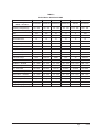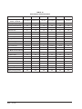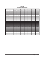
1
INSTALLATION INSTRUCTIONS
SINGLE PACKAGE
AIR CONDITIONERS
MODELS
P1124A3
P1130A2
P1136A2
P1142A3
P1148A2
P1060A1
P1224A2
P1230A1
P1236A1
P1242A1
P1248A2
Bard Manufacturing Company, Inc.
Bryan, Ohio 43506
Since 1914 . . . Moving ahead just as planned
© Copyright 2004
Manual :
Supersedes:
File:
Date:
2100-353F
2100-353E
Volume II Tab 10
12-20-06
Manual
Page
2100-353F
1 of 26
CONTENTS
Getting Other Informations and Publications ........ 3
General Instructions
Important ................................................................
Shipping Damage ....................................................
General ................................................................
Field Installed Heater Packages (Optional) .............
4
4
4
4
Installation
Location ............................................................... 11
Typical Installations ....................................... 11 & 16
Condensate Drain Trap ......................................... 16
Air Filters .............................................................. 16
Wiring – Main Power ............................................. 17
Wiring – 24V Low Voltage Control Circuit ............. 17
Transformer Taps ................................................... 17
Thermostats ........................................................... 17
Start Up and Operation
Three Phase Scroll Compressor Start Up
Information ............................................................. 19
Sequence of Operation .......................................... 19
Start Up Notes ....................................................... 19
Indoor Blower Motor .............................................. 19
Compressor Control Module .......................... 19 & 20
Adjustments ........................................................... 20
Service and Troubleshooting
Service Hints ......................................................... 21
Pressure Service Ports .......................................... 21
Refrigerant Charge ................................................ 21
Fan Blade Settings ................................................ 21
Suction and Discharge Tube Brazing .................... 22
Pressure Tables ............................................. 23 & 24
Wiring Diagram ...................................................... 18
Troubleshooting GE ECM™ Blower Motors ... 25-26
Tables
Figures
Figure 1
Figure 2
Figure 3
Figure 4
Figure 5
Figure 6
Figure 7
Figure 8
Figure 9
Figure 10
Figure 11
Figure 12
Figure 13
Figure 14
Unit Dimensions ....................................
Slab Mounting at Ground Level ............
Airflow & Service Access Clearances ...
Roof Top Application .............................
Elevated Mounting Platforms ................
Prefabricated Rood Curb
Specifications ........................................
Field Fabricated Curbing .......................
Condensate Drain Trap .........................
Low Voltage Wiring ...............................
Fan Blade Setting .................................
Brazing Diagram ...................................
Control Disassembly .............................
Winding Test .........................................
Drip Loop ..............................................
Manual 2100-353F
Page
2 of 26
10
12
12
13
13
14
15
16
18
21
22
26
26
26
Table 1 Rated CFM & ESP .................................. 4
Table 2 Electrical Specifications .......................... 5
Table 2A Electrical Specifications .......................... 6
Table 2B Electrical Specifications .......................... 7
Table 3 Option Field Installed Heater Packages .. 8
Table 4 Electric Heater Table ............................... 9
Table 5 Unit Dimensions .................................... 10
Table 6 Roof Curb Details .................................. 15
Table 7 Dimension for Figure 7 .......................... 15
Table 8 Filter Requirements & Sizes ................. 16
Table 9 Thermostat Wire Size ........................... 17
Table 10 Wall Thermostat .................................... 17
Table 11 Suction Line Temperatures ................... 21
Table 12 Fan Blade Setting Dimensions .............. 21
Table 13 Indoor Blower Performance .................. 22
Table 14 Pressure Table ...................................... 23
Table 14A Pressure Table ...................................... 24
Getting Other Information and Publications
These publications can help you install the air
conditioner or heat pump. You can usually find these at
your local library or purchase them directly from the
publisher. Be sure to consult current edition of each
standard.
FOR MORE INFORMATION, CONTACT
THESE PUBLISHERS:
ACCA
Air Conditioning Contractors of America
1712 New Hampshire Ave. N.W.
Washington, DC 20009
Telephone: (202) 483-9370
Fax: (202) 234-4721
ANSI
American National Standards Institute
11 West Street, 13th Floor
New York, NY 10036
Telephone: (212) 642-4900
Fax: (212) 302-1286
National Electrical Code ...................... ANSI/NFPA 70
Standard for the Installation .............. ANSI/NFPA 90A
of Air Conditioning and Ventilating Systems
Standard for Warm Air ...................... ANSI/NFPA 90B
Heating and Air Conditioning Systems
Load Calculation for ............................ ACCA Manual J
Residential Winter and Summer Air Conditioning
Duct Design for Residential .............. ACCA Manual D
Winter and Summer Air Conditioning and Equipment
Selection
ASHRAE American Society of Heating, Refrigerating,
and Air Conditioning Engineers, Inc.
1791 Tullie Circle, N.E.
Atlanta, GA 30329-2305
Telephone: (404) 636-8400
Fax: (404) 321-5478
NFPA
National Fire Protection Association
Batterymarch Park
P.O. Box 9101
Quincy, MA 02269-9901
Telephone: (800) 344-3555
Fax: (617) 984-7057
Manual 2100-353F
Page
3 of 26
GENERAL INSTRUCTIONS
IMPORTANT
The equipment covered in this manual is to be installed
by trained, experienced service and installation
technicians. All duct work, supply and return ducts,
must be properly sized for the design airflow
requirement of the equipment. ACCA is an excellent
guide to proper sizing. All duct work or portions thereof
not in the conditioned space should be properly
insulated in order to both conserve energy and prevent
condensation or moisture damage.
SHIPPING DAMAGE
Upon receipt of equipment, the carton should be
checked for external signs of shipping damage. If
damage is found, the receiving party must contact the
last carrier immediately, preferably in writing,
requesting inspection by the carrier’s agent.
GENERAL
The refrigerant system is completely assembled and
charged. All internal wiring is complete.
The unit is designed for use with or without duct work.
Flanges are provided for attaching the supply and return
ducts.
These instructions explain the recommended method to
install the air cooled self-contained unit and the
electrical wiring connections to the unit.
These instructions and any instructions packaged with
any separate equipment required to make up the entire
heat pump system should be carefully read before
beginning the installation. Note particularly “Starting
Procedure” and any tags and/or labels attached to the
equipment.
While these instructions are intended as a general
recommended guide, they do not supersede any national
and/or local codes in any way. Authorities having
jurisdiction should be consulted before the installation is
made.
Manual 2100-353F
Page
4 of 26
FIELD INSTALLED HEATER PACKAGES
(OPTIONAL)
These packaged air conditions are manufactured without
supplementary electric heaters. Supplementary heaters
are available for simple, fast field installation.
A separate power circuit is required for the
supplementary heaters.
IMPORTANT: Refer to Table 1 when designing duct
work for maximum available static pressure with heater
installed.
Refer to data shown in Tables 3 and 4 for proper
application information on all available heater
combinations and what units they can be used with. It
also shows the applicable circuit ampacities, fuse size,
and wire size for each heater combination.
TABLE 1
RATED CFM AND EXTERNAL STATIC
PRESSURE (ESP)
Model
N o.
Rated
C FM
Recommended
Airflow Range
Rated
ESP
Max.
ESP
P1124A3
800
720 - 880
0.20
0.50
P 1224A 2
800
Note 1
0.10
0.50
P1130A2
1125
1020 - 1275
0.20
0.50
P 1230A 1
1000
Note 1
0.15
0.50
P1136A2
1250
1150 - 1400
0.30
0.50
P 1236A 1
1100
Note 1
0.15
0.50
P1142A3
1400
1260 - 1540
0.20
0.40
P 1242A 1
1400
Note 1
0.20
0.50
P1148A2
1550
1400 - 1700
0.40
0.50
P 1248A 2
1550
Note 1
0.20
0.50
P 1060A 1
1700
1530 - 1870
0.20
0.50
NOTE: ECM motors provide rated CFM up to 0.50 ESP
TABLE 2
ELECTRICAL SPECIFICATIONS
Model
Electric Rating –
60 Hz – Circuit A
P1124A3
P1130A2
P1136A2
P1136A1-B
230/208-60-1 230/208-60-1 230/208-60-1 230/208-60-3
P1136A1-C
P1142A3
460-60-3
230/208-60-1
Operating Voltage Range
197 - 253
197 - 253
197 - 253
187 - 253
414 - 506
197 - 253
Minimum Circuit Ampacity
16
21
25
18
12
29
10.3
13.6
16
11
6
18.5
Field Wire Size *
12
10
8
10
14
8
Ground Wire Size
12
10
10
10
14
10
Delay Fuse – Max. **
25
30
40
25
15
45
11.8/12.3
15.4/16.9
17.1/18.7
12.3/12.9
7.3
23.1/24.2
Scroll
Scroll
Scroll
Scroll
Scroll
Scroll
230/208
230/208
230/208
230/208
460
230/208
Rated Load Amps
8.5/9.0
12.1/13.6
13.8/15.4
9.0/9.6
4.9
17.0/18.5
Lock Roter Amps
54/54
72.5/72.5
88/88
77/77
39
104/104
1/5 - 1090
1/5 - 1075
1/5 - 1075
1/5 - 1075
1/5 - 1075
1/2 - 1075
Fan Motor Amps
1.2
1.6
1.6
1.6
1.0
2.5
Fan – Dia./CFM
20"/1942
20"/2400
20"/2100
20"/2000
20"/2000
24"/2850
1/3 - 1075
1/5 - 1075
1/5 - 1075
1/5 - 1075
1/5 - 1075
1/2 - 1075
Blower Motor – Amps
2.1
2.6
2.6
2.6
1.4
3.7
CFM Cooling & ESP
800 @ 0.20
1125 @ 0.20
1250 @ 0.30
1275 @ 0.30
Charge (R-22 oz.)
52
64
93
93
93
89
Shipping Weight (pounds)
300
310
330
330
330
390
BC SC
Total unit Amps – 230/208
Compressor – Circuit A
Compressor Type
Volts
Fan Motor and Condenser
Fan Motor – HP/RPM
Motor and Evaporator
Blower Motor – HP/RPM
1275 @ 0.30 1400 @ 0.20
Manual 2100-353F
Page
5 of 26
TABLE 2A
ELECTRICAL SPECIFICATIONS
Model
Electric Rating –
60 Hz – Circuit A
P1148A2
P1148A2-B
230/208-60-1 230/208-60-3
P1148A2-C
460-60-3
P1060A1
P1060A1-B
230/208-60-1 230/208-60-3
P1060A1-C
460-60-3
Operating Voltage Range
197 - 253
187 - 253
414 - 506
197 - 253
187 - 253
414 - 506
Minimum Circuit Ampacity
32
25
12
43
29
14
20.5
14.7
7
29
12
9
Field Wire Size *
8
10
12
8
8
12
Ground Wire Size
10
10
12
10
10
12
Delay Fuse – Max. **
50
35
15
60
45
20
24.2/26.2
17.9/19.1
8.8
30.9/33.7
21.7/23.7
11.2
Scroll
Scroll
Scroll
Scroll
Scroll
Scroll
Volts
230/208
230/208
460
230/208
230/208
460
Rated Load Amps
18.5/20.5
12.2/13.4
6
25.2/28.2
16/18
8.4
Lock Roter Amps
137/137
91/91
50
169/169
123/123
62
1/3 - 850
1/3 - 850
1/3 - 850
1/3 - 850
1/3 - 850
1/3 - 850
Fan Motor Amps
2.5
2.5
1.2
2.5
2.5
1.2
Fan – Dia./CFM
24"/3100
24"/3100
24"/3100
24"/3100
24"/3100
24"/3100
1/2 - 1075
1/2 - 1075
1/2 - 1075
1/2 - 1075
1/2 - 1075
1/2 - 1075
Blower Motor – Amps
3.7
3.7
1.8
3.7
3.7
1.8
CFM Cooling & ESP
1550 @ 0.40
1550 @ 0.40
1550 @ 0.40
1700 @ 0.20
1700 @ 0.20
1700 @ 0.20
120
120
120
425
425
425
BC SC
Tota unit Amps – 230/208
Compressor – Circuit A
Compressor Type
Fan Motor and Condenser
Fan Motor – HP/RPM
Motor and Evaporator
Blower Motor – HP/RPM
Charge (R-22 oz.)
Shipping Weight (pounds)
Manual 2100-353F
Page
6 of 26
430
430
430
TABLE 2B
ELECTRICAL SPECIFICATIONS
Model
Electric R ating –
60 H z – C ircuit A
P1224A2
P1230A1
P1236A1
P1236A1-B
P1242A1
P1248A2
P1248A2-B
230/208-60-1 230/208-60-1 230/208-60-1 230/208-60-3 230/208-60-1 230/208-60-1 230/208-60-3
Operati ng Voltage Range
197 - 253
197 - 253
197 - 253
187 - 253
197 - 253
197 - 253
187 - 253
Mi ni mum C i rcui t Ampaci ty
15
21
25
19
30
34
23
10.3
13.5
16.2
10.9
18
21
12.8
Fi eld Wi re Si ze *
BC SC
12
10
8
10
8
6
8
Ground Wi re Si ze
12
10
10
10
10
10
10
D elay Fuse – Max. **
20
30
40
25
45
50
35
11.7/12.4
15.7/17.1
19.2/21.1
14.9/15.8
23.2/24.1
25.5/27
19.4/19.7
Scroll
Scroll
Scroll
Scroll
Scroll
Scroll
Scroll
230/208
230/208
230/208
230/208
230/208
230/208
230/208
Rated Load Amps
8.5/9.0
11.4/12.8
14.3/16.2
10/10.9
16.4/17.3
18.5/20
12.4/12.7
Lock Roter Amps
54/54
76/76
90.5/90.5
77/77
104/104
137/137
91/91
1/5 - 1090
1/5 - 1075
1/5 - 1075
1/5 - 1075
1/3 - 825
1/3 - 825
1/3 - 825
Fan Motor Amps
1.2
1.6
1.6
1.6
2.5
2.5
2.5
Fan – D i a./C FM
20"/1975
20"/2400
20"/2100
20"/2100
24"/2900
24"/2350
24"/2350
Tota uni t Amps – 230/208
C ompressor – C ircuit A
C ompressor Type
Volts
Fan Motor and C ondenser
Fan Motor – HP/RPM
Motor and Evaporator
1/3 Vari able
1/2 Vari able
1/2 Vari able
1/2 Vari able
1/2 Vari able
1/2 Vari able
1/2 Vari able
Blower Motor – Amps
Blower Motor – HP/RPM
2.2
2.7
3.3
3.3
4.3
4.5
4.5
C FM C ooli ng & ESP
800 @ 0.10
1000 @ 0.15 1100 @ 0.15 1100 @ 0.15 1400 @ 0.20 1550 @ 0.20 1550 @ 0.20
C harge (R-22 oz.)
53
88
102
102
118
151
151
Shi ppi ng Wei ght (pounds)
300
330
340
340
410
430
430
Manual 2100-353F
Page
7 of 26
Manual 2100-353F
Page
8 of 26
240/208-1
240/208-1
240/208-1
240/208-1
240/208-1
240/208-1
240/208-1
240/208-3
240/208-3
480-3
480-3
Volts &
P h ase
240/208-1
240/208-1
240/208-1
240/208-1
240/208-3
240/208-3
240/208-3
480-3
480-3
480-3
EH3PB-A05
EH3PB-A08
EH3PB-A10
EH3PB-A15
EH3PC-A05
EH3PC-A10
EH3PC-A15
EH3PB-B09
EH3PB-B15
EHPB-C09
EHPB-C15
Heater Package
Model
EH5PB-A05
EH5PB-A10
EH5PB-A15
EH5PB-A20
EH5PB-B09
EH5PB-B15
EH5PB-B18
EH5PC-C09
EH5PC-C15
EH5PC-C18
A
A
A
A
A
A
S
S
S
S
P1142A3
NA
NA
NA
A
NA
NA
NA
NA
S
S
S
P1124A3
A
A
A
A
NA
NA
NA
S
S
S
S
P1130A2
NA
A
A
A
NA
NA
A
NA
NA
NA
S
NA
NA
S
NA
S
S
S
S
P1236A2
S
NA
NA
P1230A1
NA
NA
NA
NA
A
A
A
A
A
A
A
S
NA
A
S
S
S
S
S
S
NA
NA
NA
NA
A
A
NA
S
S
S
P1248A2
A
A
S
S
NA
NA
NA
A
A
A
A
NA
NA
NA
NA
S
NA
S
NA
S
NA
NA
NA
NA
S
S
NA
NA
NA
NA
NA
NA
NA
This column
is left blank
intentionally.
NA
NA
NA
NA
S
S
NA
A
A
A
A
A
A
A
A
A
S
S
S
S
A
A
A
S
S
S
A
A
A
A
S
S
S
A
A
A
A
A
A
A
P1248A2-B P1060A1 P1060A1-B P1060A1-C
S
S
A
A
NA
NA
NA
A
A
A
A
P1136A1-C P1136A1-C P1236A1 P1236A1-B
A = Alternate Application – Heater volts and phase different from basic unit.
S
S
A
A
S
A
A
A
A
A
A
A
A
S
S
S
A
A
A
A
P1242A1 P1148A2 P1148A2-B P1148A2-C
NA
NA
NA
NA
NA
S
S
NA
NA
NA
NA
P1124A2
S = Standard Application – Heater volts and phase same as basic unit
N = Not Approved
Volts &
P h ase
Heater Package
Model
TABLE 3
OPTIONAL FIELD INSTALLED HEATER PACKAGES
ONLY TO BE USED WITH THE MODELS INDICATED
Manual 2100-353F
Page
9 of 26
240/208-1
240/208-1
240/208-3
240/208-3
480-3
480-3
EH3PB-A05
EH3PB-A08
EH3PB-A10
EH3PB-A15
EH3PC-A05
EH3PC-A10
EH3PC-A15
EH5PB-A05
EH5PB-A10
EH5PB-A15
EH5PB-A20
EH3PB-B09
EH3PB-B15
EH5PB-B09
EH5PB-B15
EH5PB-B18
EH3PB-C09
EH3PB-C15
EH5PB-C09
EH5PB-C15
EH5PB-C18
10
10
10
10
10
10/10
8/8
10/10
8/8
6/8
14
10
14
10
10
30/25
50/40
30/25
50/40
60/50
15
25
15
25
30
28/24
46/39
28/24
46/39
55/47
15
23
15
23
28
1
1
1
1
1
1
1
1
1
1
21.7/18.7
36.2/31.2
21.7/18.7
36.2/31.2
43.4/37.5
10.8
18.0
10.8
18.0
21.7
9 30,700 6.75 23,000
15 51,200 11.25 38,400
9 30,700 6.75 23,000
15 51,200 11.25 38,400
18 61,400 13.50 46,100
9 30,700 8.26 28,200
15 51,200 13.77 47,000
9 30,700 8.26 28,200
15 51,200 13.77 47,000
18 61,400 16.53 56,400
14
10
10
14
10
10
10
8
6
30/60
60/60
10/10
6/8
4/4
2/3
30/25
60/50
80/70
110/100
26/23
53/46
79/68
104/91
1
1
1
1
20.8/18.1
41.6/36.2
62.5/54.1
83.2/72.1
17,100 3.75
34,100 7.50
51,200 11.25
68,200 15.00
30/60
12,800
26,000
38,400
51,200
10
10
10
8
10
10
8
10/10
10/10
6/8
4/4
10/10
6/8
4/4
30/25
45/40
60/50
80/70
30/25
60/50
80/70
26/23
42/36
53/46
79/68
26/23
53/46
79/68
1
1
1
1
1
1
1
5
10
15
20
KW
30/60
B TU H
20.8/18.1
33.3/28.8
41.6/36.2
62.5/54.1
20.8/18.1
41.6/36.2
62.5/54.1
KW
17,100 3.75 12,800
27,300 6.00 20,500
34,100 7.50 26,000
51,200 11.25 38,400
17,100 3.75 12,800
34,100 7.50 26,000
51,200 11.25 38,400
3
Ground
Wire
Siz e
2
Field
P o w er
Wiring
5
8
10
15
5
10
15
1
Max. Over
Min.
Current
No. Field Circuit
Circuits Ampacity Protection
240/208V
Htr. Amps
Heater
Internal
F u ses
Circuit B
B TU H
Htr. KW &
Capacity
@ 208 Volts
IMPORTANT: While this electrical data is presented as a guide, it is important to electrically connect properly sized fuses and
conductor wires in accordance with the National Electrical Code and all existing local codes.
3 Based upon Table 250-95 of N.E.C. 1993. See electric data for basic heat pump for Circuit A wiring specification requirements.
2 Based on wire suitable for 75 degree C. Other wiring materials must be rated for marked “Minimum Circuit Ampacity” or greater.
1 Time Delay fuses of “HACR” type circuit breakers must be used for 60 and smaller sizes. Standard fuses or circuit breakers are suitable for sizes 70 and
larger. 480V circuit breakers are not “HACR” type.
Unit Volts
P h ases
Heater Pkg.
Model No.
Htr. KW &
Capacity
@ 240 Volts
TABLE 4
OPTIONAL FIELD INSTALLED ELECTRIC HEATER TABLE
FIGURE 1
DIMENSIONS OF UNITS
TABLE 5
DIMENSIONS OF UNITS
Duct Opening (Inches)
Model
N o.
Nominal Cabinet Dimensions (Inches)
A
B
C
J
P1124A3
P 1224A 2
P1130A2
24-1/4 48-3/16 38-1/8 26-1/8
P 1230A 1
P1136A2
P 1236A 1
P1142A3
P 1242A 1
P1148A2 31-1/4
P 1248A 2
P 1060A 1
Manual 2100-353F
Page
10 of 26
50
42
26
Discharge
Return Air
K
L
M
D
E
F
G
H
2-1/8
9/16
9/16
33
6
33
14
7/8
3
2-3/4
7-9/16
38
10
38
16
1-3/8
INSTALLATION
LOCATION
TYPICAL INSTALLATIONS
GENERAL
1. ROOF MOUNTED – The unit is mounted on a
sturdy base on the roof of the building. Return air to
the unit is brought through a single return grille
(grilles with built-in filters are best since they enable
easy access for filter changing). Return air ducts are
attached to the lower section of the front panel.
Supply air is brought from the unit to attic duct work
or to a furred down hall. Supply air duct is attached
to the top of the front panel.
The unit must be located outside, or in a well ventilated
area. It must not be in the space being heated or cooled.
A sound absorbing material should be considered if the
unit is to be installed in such a position or location that
might cause transmission of sound or vibration to the
living area or adjacent buildings.
SLAB MOUNTING
In areas where winter temperatures DO NOT go below
32° F for periods over twelve hours, the unit may be
slab mounted at grade level. When installing unit at
grade level, install on a concrete slab at least four inches
above finished grade level. Slab should have a slope
tolerance away from the building structure of at least ¼
inch per foot, while being level from side to side. Place
slab in a location where runoff water from higher
ground will not collect around unit. See Figure 2.
A minimum of 18 inches should be provided between
the coil inlet and any building surfaces. Provide at least
four feet between coil outlet and any building wall,
fences or other vertical structures. Provide a minimum
of three feet clearance on the service access side of the
unit. See Figure 3.
ROOF MOUNTING
When a unit is installed in areas where low ambient
temperatures or strong winter winds exist, it should be
placed for prevailing winter winds are not in direct line
with the outdoor coil. If this is not possible, a wind
barrier should be constructed. Place barrier 24 inches
from the coil inlet side of the unit and in the direction of
prevailing winds. Size barrier at least the same height
and width as the unit. This may be necessary on ground
level installations also. See Figure 4.
WINTER INSTALLATION BELOW 32°F
In areas where winter conditions go below 32°F for
extended periods, the unit must be elevated above the
mounting surface to prevent snowfall or ice
accumulation from interfering with the operation of the
unit. A minimum of twelve inch elevation is
recommended, while greater elevation may be required
for areas of high snow accumulation. Poured concrete,
steel framework, brick, cement block, etc., can be
utilized to construct a suitable raised mounting platform.
See Figure 5.
CAUTION: All outdoor duct work must be
thoroughly insulated and
weatherproofed. All attic duct work
must be thoroughly insulated. 2-inch
thick insulation with suitable vapor
barrier is recommended for both outdoor
and attic runs.
In roof top installation, as in all installations, the air
conditioner must be level from side to side.
However, the unit should have a pitch along the
length to assure complete external drainage of
precipitation and of defrost condensate. See Figures
6 and 7, and Tables 6 and 7.
2. CRAWL SPACE – Duct work installed in crawl
space must be well insulated and provided with a
vapor barrier. In addition, the crawl space must be
thoroughly ventilated and provided with a good
vapor barrier as a ground cover. It is most desirable
to install the unit will be outdoors rather than inside
the crawl space, so that it will be readily accessible
for service.
3. SLAB MOUNTED AT GROUND LEVEL – This
type installation is ideal for homes with a slab floor
construction where a roof mounted unit is not
desired. The supply and return duct work can be run
through a furred closet space.
4. THROUGH THE WALL – This type installation
requires a suitable framework to be fabricated
capable of withstanding the unit weight. Normally
the unit will be insulated so as to minimize supply
and return duct work.
Manual 2100-353F
Page
11 of 26
FIGURE 2
SLAB MOUNTING AT GROUND LEVEL
(Above 32°F Outside Temperature)
FIGURE 3
AIRFLOW AND SERVICE ACCESS CLEARANCES
Manual 2100-353F
Page
12 of 26
FIGURE 4
ROOF TOP APPLICATION
(May also be required for ground level installations)
FIGURE 5
ELEVATED MOUNTING PLATFORMS
Manual 2100-353F
Page
13 of 26
Manual 2100-353F
Page
14 of 26
FIGURE 6
PREFABRICATED ROOF CURB SPECIFICATIONS
HEAVY GAUGE GALVANIZED WITH WOOD NAILING STRIP, WELDED/LEAKPROOF
ONCE PIECE CONSTRUCTION – READY TO INSTALL
TABLE 6
ROOF CURB DETAILS
(Refer to Figure 7)
R oof
H ood
Unit Model Model
R oof
Curb
Model
Roof Curb Details
A
B
C
D
E
F
P1124A3
P 1224A 2
P1130A2
P 1230A 1
P1136A2
P 1236A 1
RHE-36 9042-003 80.375 40.25
P1142A3
P 1242A 1
P1148A2
P 1248A 2
P 1060A 1
RHE-60 9042-004 82.375 44.125 41.125 38.375 35.375 44
37.25 38.375 35.375 42
G
H
I
J
K
L
24.25 19.125 48.188 14.75 38.125 38.25
31.25 19.125
50
14.75
42
38.25
FIGURE 7
FIELD FABRICATED CURBING
TABLE 7
DIMENSION FOR X IN FIG. 7
Unit Model
Roof Hood Dimension
Model
X
P1124A3
P 1224A 2
P1130A2
P 1230A 1
P1136A2
P 1236A 1
RHE-36
41
P1142A3
P 1242A 1
P1148A2
P 1248A 2
P 1060A 1
RHE60
44-7/8
Manual 2100-353F
Page
15 of 26
5. OTHER INSTALLATIONS – Many other
installations are possible with the packaged air
conditioner. No matter what the installation, always
consider the following facts:
A. Insure that the discharge air is not obstructed in
any way so as to cause operation difficulties.
B. The indoor coil drain pan is equipped with a
coupling that must be piped through a
condensate drain trap to a suitable drain.
C. Always mount the unit in such a position that it
may be easily reached for servicing and
maintenance.
D. Insure that the unit is clear so that proper airflow
over the outdoor coil will be maintained.
If this unit is operated in cooling below a 65° outdoor
ambient temperature, the installation of low ambient
controls (CMA-6) to unit is required.
CONDENSATE DRAIN TRAP
It is very important to provide a trap in the condensate
drain line to allow a positive liquid seal in the line and
assure correct drainage from the coil condensate pan.
Install condensate drain trap shown in Figure 8. Use
drain connection size or larger. Do not operate unit
without trap. Unit must be level or slightly inclined
toward drain. With a trap installed on a unit located in
an unconditioned area, water in the trap may freeze. It
is recommended that the trap material be of a type that
will allow for expansion of water when it freezes.
AIR FILTERS
Air filters for the return air side of the system are not
provided as part of these models, and must be field
supplied and installed as part of the final installation.
Prior thought should be given to return air location and
placement of the air filter(s). The air filter(s) must be of
adequate size and readily accessible to the operator of
the equipment. Filters must be adequate in size and
properly maintained for proper operation. If this is not
done, excessive energy use, poor performance, and
multiple service problems will result. It is impossible to
oversize air filters. Generous sizing will result in
cleaner air and coils as well as lower operating costs and
extend the time between required changes. Table 8
shows minimum filter areas and recommended filter
sizes. Actual filter sizes can vary with the installation
due to single or multiple returns utilizing a filter/grille
arrangement or being placed immediately ahead of the
indoor coil face in the return air duct.
TABLE 8
FILTER REQUIREMENTS & SIZES
Model No.
Minimum Filter Area
Recommended
Siz e
P1124A3
P 1224A 2
P1130A2
P 1230A 1
P1136A2
P 1236A 1
462 Square Inches
(3.21 Square Feet)
15x30-5/8x1
P1142A3
P 1242A 1
P1148A2
P 1248A 2
P 1060A 1
608 Square Inches
(4.62 Square Feet)
(2) 16x20x1
NOTE: If roof hood accessory is to be used, information
on air filters may be found under that heading in
this manual. Air filters are supplied as part of
that package.
FIGURE 8
CONDENSATE DRAIN TRAP
Manual 2100-353F
Page
16 of 26
WIRING – MAIN POWER
Refer to the unit rating plate for wire sizing information
and maximum fuse size. Each outdoor unit is marked
with a “Minimum Circuit Ampacity”. This means that
the field wiring used must be sized to carry that amount
of current. If field installed heaters are added to the
basic unit, a second separate power supply circuit will
be required. The heater rating plate located adjacent to
the basic unit rating plate will show the appropriate
circuit ampacity fuse size, etc. (Also see “Electrical
Specifications” on pages 5, 6 and 7.) All models are
suitable for connection with copper wire only. These
instructions must be adhered to. Refer to the National
Electrical Code for complete current carrying capacity
data on the various insulation grades of wiring material.
The electrical specifications list fuse and wire sizes
(75°F copper) for all models including the most
commonly used heater sizes.
The unit rating plate lists a “Maximum Time Delay
Fuse” or “HACR” type circuit breaker that is to be used
with the equipment. The correct size must be used for
proper circuit protection and also to assure that there
will be no nuisance tripping due to the momentary high
starting current of the compressor.
WIRING – 24V LOW VOLTAGE
CONTROL CIRCUIT
TABLE 9
THERMOSTAT WIRE SIZE
Transformer VA
55
FLA Wire Gauge
2.3
Maximum
Distance
In Feet
20
18
16
14
12
45
60
100
160
250
TRANSFORMER TAPS
230/208V, 1 phase and 3 phase equipment employ dual
primary voltage transformers. All equipment leaves the
factory wired on 240V tap. For 208V operation,
reconnect from 240V to 208V tap. The acceptable
operating voltage range for the 240 and 208V taps are:
TAP
RANGE
240
253 – 216
208
220 – 187
NOTE: The voltage should be measured at the field
power connection point in the unit and while
the unit is operating at full load (maximum
amperage operating condition).
Five (5) wires should be run from thermostat subbase to
the 24V terminal board in the unit. A five conductor, 18
gauge copper, color-coded thermostat cable is
recommended. The connection points are shown in
Figure 9.
THERMOSTATS
See specific wiring information for the different models, heater KWs, and voltages on unit and heating wiring
diagrams.
TABLE 10
WALL THERMOSTAT
Thermostat
Predominant Features
8403-049
(1F93-380)
2 stage Cool; 2 stage Heat
Programmable Electronic
Auto or Manual changeover
1 stage Cool; 1 stage Heat
8403-057
Electronic Non-Programmable
(TH3110D1040)
Manual changeover
IMPORTANT NOTE:
Only the thermostats shown above are recommended for use with this equipment.
Manual 2100-353F
Page
17 of 26
FIGURE 9
LOW VOLTAGE WIRING
Low Voltage Wiring
Thermostat Subbase
C
G
R
Y1
Y2
B
W1
W2
TH3110D1040
C
G
R
Y
Rc
B
W1
W2
Unit 24V
Terminal
Block
C
G
R
Y
Y1
B
W1
W2
IF93-380
W3
A1
E2
P
L
E
L
E
L
E
D
OR
W3
DH
D1
REMOVE JUMPER FOR 2 STAGE ELECTRIC
HEAT ON UNITS WITH 15 OR MORE KW
Unit Control Panel
MIS-2270
Manual 2100-353F
Page
18 of 26
START UP AND OPERATION
THREE PHASE SCROLL COMPRESSOR
START UP INFORMATION
Scroll compressors, like several other types of
compressors, will only compress in one rotational
direction. Direction of rotation is not an issue with
single phase compressors since they will always start
and run in the proper direction.
However, three phase compressors will rotate in either
direction depending upon phasing of the power. Since
there is a 50-50 chance of connecting power in such a
way as to cause rotation in the reverse direction,
verification of proper rotation must be made.
Verification of proper rotation direction is made by
observing that suction pressure drops and discharge
pressure rises when the compressor is energized.
Reverse rotation also results in an elevated sound level
over that with correct rotation, as well as, substantially
reduced current draw compared to tabulated values.
START UP NOTES
For improved start up performance, wash the indoor coil
with dishwasher detergent.
INDOOR BLOWER MOTOR
Some models feature a variable speed (ECM) motor
providing high efficiency, low sound levels and soft
start capabilities. The motor is self-adjusting to provide
the proper airflow rate at duct static pressures up to
0.50" WC without user adjustment or wiring changes.
On command from the wall thermostat, the motor will
start slowly and ramp up to full speed over a period of
10-15 seconds.
When the thermostat is satisfied, the blower will operate
for approximately 1 minute, and then slow down and
stop.
Verification of proper rotation must be made at the
time the equipment is put into service. If improper
rotation is corrected at this time there will be no
negative impact on the durability of the compressor.
However, reverse operation for over one hour may have
a negative impact on the bearing due to oil pump out.
COMPRESSOR CONTROL MODULE
NOTE: If compressor is allowed to run in reverse
rotation for several minutes the compressor’s
internal protector will trip.
ADJUSTABLE DELAY-ON-MAKE AND BREAK
TIMER
All three phase ZR*3 compressors are wired identically
internally. As a result, once the correct phasing is
determined for a specific system or installation,
connecting properly phased power leads to the same
Fusite terminals should maintain proper rotation
direction.
The direction of rotation of the motor may be changed
by reversing any two line connections to the unit.
SEQUENCE OF OPERATION
COOLING – Circuit R-Y makes at thermostat pulling
in compressor contactor starting the compressor and
outdoor motor. The G (indoor motor) circuit is
automatically completed on any call for cooling
operation, or can be energized by manual fan switch on
subbase for constant air circulation.
HEATING – A circuit R-W1 is completed on each
heating cycle energizing electric heat if so equipped.
The compressor control is an anti-short cycle/lockout
timer with high and low pressure switch monitoring and
alarm output.
On a call for compressor operation, the delay-on-make
period begins which will be 10% of the delay-on-break
setting. When the delay-on-make is complete and the
high pressure switch (and low pressure switch if
employed) is closed, the compressor contactor is
energized. Upon shutdown, the delay-on-break timer
starts and prevents restart until the delay-on-break and
delay-on-make periods have expired.
HIGH PRESSURE SWITCH AND LOCKOUT
SEQUENCE (Standard Feature)
If the high pressure switch opens, the compressor
contactor will de-energize immediately. The lockout
timer will go into a soft lockout and stay in soft lockout
until the high pressure switch closes and the delay-onmake time has expired. If the high pressure switch
opens again in this same operating cycle the unit will go
into manual lockout condition and the alarm circuit will
energize. Recycling the wall thermostat resets the
manual lockout.
Manual 2100-353F
Page
19 of 26
LOW PRESSURE SWITCH, BYPASS, AND
LOCKOUT SEQUENCE
ADJUSTMENTS
NOTE: The low pressure switch is an optional control
and the bypass and lockout sequence are part
of the standard compressor control module.
ADJUSTABLE DELAY-ON-MAKE AND
DELAY-ON-BREAK TIMER
If the low pressure switch opens for more that 120
seconds, the compressor contactor will de-energize and
go into a soft lockout. Regardless the state of the low
pressure switch, the contactor will reenergize after the
delay-on-make time delay has expired. If the low
pressure switch remains open or opens again for longer
than 120 seconds the unit will go into manual lockout
condition and the alarm circuit will energize. Recycling
the wall thermostat resets the manual lockout.
ALARM OUTPUT
Alarm terminal is output connection for applications
where alarm signal is desired. This terminal is powered
whenever compressor is locked out due to HPC or LPC
sequences as described.
NOTE: Both high and low pressure switch controls are
inherently automatic reset devices. The high
pressure switch and low pressure switch cut out
and cut in settings are fixed by specific air
conditioner or heat pump unit model. The
lockout features, both soft and manual, are a
function of the Compressor Control Module.
Manual 2100-353F
Page
20 of 26
The potentiometer is used to select Delay-on-Break time
from 30 seconds to 5 minutes. Delay-on-Make (DOM)
timing on power-up and after power interruptions is
equal to 2 minutes plus 10% of Delay-on-Break (DOB)
setting:
0.5 minute
1.0 minute
2.0 minute
3.0 minute
4.0 minute
5.0 minute
(30 seconds)
(60 seconds)
(120 seconds)
(160 seconds)
(240 seconds)
(300 seconds)
DOB
DOB
DOB
DOB
DOB
DOB
=
=
=
=
=
=
123 second DOM
126 second DOM
132 second DOM
138 second DOM
144 second DOM
150 second DOM
SERVICE AND TROUBLESHOOTING
SERVICE HINTS
FAN BLADE SETTINGS
1. Caution homeowner to maintain clean air filters at
all times. Also, not to needlessly close off supply
and return air registers. This reduces airflow
through the system, which shortens equipment
service life as well as increasing operating costs.
Shown in Figure 10 are the correct fan blade setting
dimensions for proper air delivery across the outdoor
coil.
2. Check all power fuses or circuit breakers to be sure
that they are the correct rating.
Any service work requiring removal or adjustment in
the fan and/or motor area will require that the
dimensions below be checked and blade adjusted in or
out on the motor shaft accordingly.
3. Periodic cleaning of the outdoor coil to permit full
and unrestricted airflow circulation is essential.
FIGURE 10
FAN BLADE SETTING
PRESSURE SERVICE PORTS
High and low pressure service ports are installed on all
units so that the system operating pressures can be
observed. Pressure tables can be found later in this
manual covering all models on cooling cycle. It is
imperative to match the correct pressure table to the
unit by model number.
AIRFLOW
REFRIGERANT CHARGE
The correct system R-22 charge is shown on the unit
rating plate. Optimum unit performance will occur
with a refrigerant charge resulting in a suction line
temperature (6" from compressor) as shown in
Table 11.
"A"
MIS-1724
TABLE 11
SUCTION LINE TEMPERATURES
TABLE 12
FAN BLADE SETTING DIMENSIONS
Model
Rated
Airflow
95° OD
Temperature
82° OD
Temperature
P1124A3
800
54 - 56
60 - 62
Model
Dimension "A"
P 1224A 2
800
55 - 58
61 - 63
P1124A3
1.00"
P1130A2
1125
56 - 58
63 - 65
P 1224A 2
1.00"
P 1230A 1
1000
56 - 58
63 - 65
P1130A2
.75"
P1136A2
1250
57 - 59
58 - 60
P 1230A 1
1.00"
P 1236A 1
1100
57 - 59
58 - 60
P1136A2
1.00"
P1142A3
1400
57 - 59
58 - 60
P 1236A 1
1.00"
P 1242A 1
1400
57 - 59
58 - 60
P1142A3
1.75"
P1148A2
1550
54 - 57
58 - 60
P 1242A 1
1.75"
P 1248A 2
1550
53 - 55
56 - 58
P1148A2
1.75"
P 1060A 1
1700
47 - 49
54 - 56
P 1248A 2
1.75"
P 1060A 1
1.75"
The above suction line temperatures are based upon 80°F dry
bulb/67°F wet bulb (50% RH) temperature and rated airflow
across the evaporator during cooling cycle.
Manual 2100-353F
Page
21 of 26
• To connect:
SUCTION AND DISCHARGE TUBE
BRAZING
Compliant Scroll compressors have copper plated steel
suction and discharge tubes. These tubes are far more
rugged and less prone to leaks than copper tubes used on
other compressors. Due to different thermal properties
of steel and copper, brazing procedures may have to be
changed from those commonly used.
• To disconnect: heat joint Areas 2 and 3 slowly and
uniformly until braze material softens and the tube
can be pulled out of suction fitting. (See Figure 11.)
– Recommended brazing materials: silfos with
minimum 5% silver or silver braze material with
flux.
– Reinsert tube into fitting.
– Heat tube uniformly in Area 1 moving slowly to
Area 2. When joint reaches brazing
temperature, apply brazing material. (See
Figure 11)
– Heat joint uniformly around the circumference
to flow braze material completely around the
joint.
– Slowly move torch into Area 3 to draw braze
material into joint. (See Figure 11.)
– Do not overheat joint.
FIGURE 11
BRAZING DIAGRAM
TABLE 13
INDOOR BLOWER PERFORMANCE
P1124A3
P1130A2
P1136A2
P1142A3
P1148A2
P1060A1
Dry / Wet
Dry / Wet
Dry / Wet
Dry / Wet
Dry / Wet
Dry / Wet
0.0
1025 / 960
1350 / 1210
1465 / 1375
1650 / 1625
1950 / 1920
1850 / 1850
0.1
935 / 870
1300 / 1160
1430 / 1340
1550 / 1525
1860 / 1830
1800 / 1780
0.2
865 / 800
1240 / 1100
1385 / 1295
1435 / 1400
1780 / 1750
1725 / 1700
0.3
835 / 770
1175 / 1035
1340 / 1250
1340 / 1310
1680 / 1660
1660 / 1625
0.4
800 / 735
1120 / 980
1275 / 1185
1230 / 1210
1580 / 1550
1580 / 1540
0.5
750 / 685
1050 / 910
1190 / 1100
1120 / 1100
1500 / 1480
1500 / 1475
ESP In
H 2O
Manual 2100-353F
Page
22 of 26
TABLE 14
PRESSURE TABLE
COOLING
Model
P1124A3
P 1224A 2
P1130A2
P 1230A 1
P1136A2
P 1236A 1
Air Temperature Entering Outdoor Coil Degrees F
Return Air
Temperature
Pressure
75 deg. D B
62 deg. WB
Low S i de
High Side
70
219
74
220
77
224
79
234
80
248
82
258
83
276
84
293
85
316
80 deg. D B
67 deg. WB
Low S i de
High Side
75
224
79
225
82
230
84
240
86
254
88
265
89
283
90
300
91
324
85 deg. D B
72 deg. WB
Low S i de
High Side
81
232
85
233
88
238
90
248
92
263
94
274
96
293
97
311
98
335
75 deg. D B
62 deg. WB
Low S i de
High Side
74
188
75
203
77
217
79
233
79
249
80
265
81
282
82
299
83
317
80 deg. D B
67 deg. WB
Low S i de
High Side
79
193
80
208
82
223
84
239
85
255
86
272
87
289
88
307
89
325
85 deg. D B
72 deg. WB
Low S i de
High Side
82
200
83
215
85
231
87
247
88
264
89
282
90
299
91
318
92
336
75 deg. D B
62 deg. WB
Low S i de
High Side
73
200
75
219
76
234
77
254
79
271
80
288
81
307
82
327
83
342
80 deg. D B
67 deg. WB
Low S i de
High Side
75
205
80
225
81
240
82
260
84
278
85
295
86
315
87
335
88
351
85 deg. D B
72 deg. WB
Low S i de
High Side
84
212
86
233
87
248
88
269
90
287
91
305
92
326
94
347
95
363
75 deg. D B
62 deg. WB
Low S i de
High Side
72
199
73
213
74
227
75
243
77
258
78
275
79
293
79
310
80
330
80 deg. D B
67 deg. WB
Low S i de
High Side
77
204
78
218
79
233
80
249
82
265
8/3
282
84
300
85
318
86
338
85 deg. D B
72 deg. WB
Low S i de
High Side
80
211
81
226
82
241
83
258
85
274
86
292
87
311
88
329
89
350
75 deg. D B
62 deg. WB
Low S i de
High Side
67
195
71
215
73
229
75
249
77
263
78
282
79
302
80
317
81
336
80 deg. D B
67 deg. WB
Low S i de
High Side
72
200
76
220
78
235
80
255
82
270
84
290
85
310
86
325
87
345
85 deg. D B
72 deg. WB
Low S i de
High Side
77
207
82
228
84
243
86
264
88
279
90
300
91
321
92
336
94
357
75 deg. D B
62 deg. WB
Low S i de
High Side
71
209
73
225
75
242
76
258
78
275
79
293
79
310
80
329
81
346
80 deg. D B
67 deg. WB
Low S i de
High Side
76
214
78
231
80
248
81
265
83
282
84
300
85
318
86
337
87
355
85 deg. D B
72 deg. WB
Low S i de
High Side
79
221
81
239
83
257
84
274
86
292
87
311
88
329
89
349
90
367
75
80
85
90
95
100
105
110
115
(Continued on Page 24 in Table 14A)
Manual 2100-353F
Page
23 of 26
TABLE 14A
PRESSURE TABLE
COOLING
Air Temperature Entering Outdoor Coil Degrees F
Model
P1142A3
P 1242A 1
P1148A2
P 1248A 2
P 1060A 1
Return Air
Temperature
Pressure
75 deg. D B
62 deg. WB
Low S i de
High Side
70
208
72
223
75
239
77
254
78
271
79
288
80
305
81
324
82
342
80 deg. D B
67 deg. WB
Low S i de
High Side
75
213
77
229
80
245
82
261
84
278
85
295
96
313
87
332
88
351
85 deg. D B
72 deg. WB
Low S i de
High Side
81
220
83
237
86
254
88
270
0
288
91
305
92
324
94
344
95
363
75 deg. D B
62 deg. WB
Low S i de
High Side
70
192
72
206
74
220
76
236
78
252
79
268
80
286
81
304
82
323
80 deg. D B
67 deg. WB
Low S i de
High Side
75
197
77
211
79
226
81
242
83
258
85
275
86
293
87
312
88
331
85 deg. D B
72 deg. WB
Low S i de
High Side
78
204
80
218
82
234
84
250
86
267
88
285
89
303
90
323
91
343
75 deg. D B
62 deg. WB
Low S i de
High Side
73
203
74
218
75
231
76
246
78
264
79
278
80
294
81
312
82
330
80 deg. D B
67 deg. WB
Low S i de
High Side
78
208
79
222
81
237
82
252
83
268
84
285
86
302
87
320
88
338
85 deg. D B
72 deg. WB
Low S i de
High Side
83
215
85
230
87
245
88
261
87
273
91
295
92
313
93
331
94
350
75 deg. D B
62 deg. WB
Low S i de
High Side
70
200
72
215
73
230
75
247
77
263
79
281
79
298
81
317
83
336
80 deg. D B
67 deg. WB
Low S i de
High Side
75
205
77
220
78
236
80
253
82
270
84
288
85
306
87
325
89
345
85 deg. D B
72 deg. WB
Low S i de
High Side
78
212
80
228
81
244
83
262
85
279
87
298
88
317
90
336
92
357
75 deg. D B
62 deg. WB
Low S i de
High Side
65
214
66
230
68
247
69
264
70
284
72
299
74
318
75
336
76
355
80 deg. D B
67 deg. WB
Low S i de
High Side
69
219
71
236
72
253
74
271
76
289
77
307
79
326
80
345
82
364
85 deg. D B
72 deg. WB
Low S i de
High Side
74
227
76
244
78
262
79
280
81
296
83
318
85
337
86
357
88
377
Manual 2100-353F
Page
24 of 26
75
80
85
90
95
100
105
110
115
TROUBLESHOOTING GE ECM BLOWER MOTORS
CAUTION:
Disconnect power from unit before removing or replacing
connectors, or servicing motor. To avoid electric shock from
the motor’s capacitors, disconnect power and wait at least 5
minutes before opening motor.
Symptom
Cause/Procedure
• Noisy blower or cabinet
• Check for loose blower housing, panels, etc.
• High static creating high blower speed?
- Check for air whistling through seams in
ducts, cabinets or panels
- Check for cabinet/duct deformation
Symptom
Cause/Procedure
Motor rocks slightly
when starting
• This is normal start-up for ECM
• “Hunts” or “puffs” at
high CFM (speed)
• Does removing panel or filter reduce
“puffing”?
- Reduce restriction
- Reduce max. airflow
Motor won’t start
• No movement
• Check blower turns by hand
• Check power at motor
• Check low voltage (24 Vac R to C) at motor
• Check low voltage connections
(G, Y, W, R, C) at motor
• Check for unseated pins in connectors on
motor harness
• Test with a temporary jumper between R - G
• Check motor for tight shaft
• Perform motor/control replacement check
• Perform Moisture Check
• Motor rocks,
but won’t start
• Check for loose or compliant motor mount
• Make sure blower wheel is tight on shaft
• Perform motor/control replacement check
Motor oscillates up
& down while being
tested off of blower
• It is normal for motor to oscillate with no load
on shaft
Motor starts, but
runs erratically
• Varies up and down
or intermittent
• Check line voltage for variation or “sag”
• Check low voltage connections
(G, Y, W, R, C) at motor, unseated pins in
motor harness connectors
• Check “Bk” for erratic CFM command (in
variable-speed applications)
• Check out system controls, Thermostat
• Perform Moisture Check
Evidence of Moisture
• Motor failure or
malfunction has occurred
and moisture is present
• Replace motor and Perform Moisture Check
• Evidence of moisture
present inside air mover
• Perform Moisture Check
Do
Don’t
• Check out motor, controls,
wiring and connections
thoroughly before replacing
motor
• Orient connectors down so
water can’t get in
- Install “drip loops”
• Use authorized motor and
model #’s for replacement
• Keep static pressure to a
minimum:
- Recommend high
efficiency, low static filters
- Recommend keeping filters
clean.
- Design ductwork for min.
static, max. comfort
- Look for and recommend
ductwork improvement,
where necessary
• Automatically assume the motor is bad.
• Locate connectors above 7 and 4 o’clock
positions
• Replace one motor or control model # with
another (unless an authorized replacement)
• Use high pressure drop filters some have ½"
H20 drop!
• Use restricted returns
• Size the equipment wisely
• “Hunts” or “puffs” at
high CFM (speed)
• Does removing panel or filter reduce
“puffing”?
- Reduce restriction
- Reduce max airflow
• Stays at low CFM
despite system call
for cool or heat CFM
• Check low voltage (Thermostat) wires and
connections
• Verify fan is not in delay mode; wait until
delay complete
• “R” missing/not connected at motor
• Perform motor/control replacement check
• Stays at high CFM
• “R” missing/not connected at motor
• Is fan in delay mode? - wait until delay time
complete
• Perform motor/control replacement check
• Oversize system, then compensate with low
airflow
• Check orientation before
• Plug in power connector backwards
inserting motor connectors • Force plugs
Moisture Check
• Blower won’t shut off
• Current leakage from controls into G, Y or W?
Check for Triac switched thermostat or solidstate relay
Excessive noise
• Determine if it’s air noise, cabinet, duct or
motor noise; interview customer, if necessary
• High static creating high blower speed?
- Is airflow set properly?
- Does removing filter cause blower to slow
down? Check filter
- Use low-pressure drop filter
- Check/correct duct restrictions
• Air noise
• Connectors are oriented “down” (or as recommended by equipment
manufacturer)
• Arrange harness with “drip loop” under motor
• Is condensate drain plugged?
• Check for low airflow (too much latent capacity)
• Check for undercharged condition
• Check and plug leaks in return ducts, cabinet
Comfort Check
• Check proper airflow settings
• Low static pressure for lowest noise
• Set low continuous-fan CFM
• Use humidistat and 2-speed cooling units
• Use zoning controls designed for ECM that regulate CFM
• Thermostat in bad location?
Manual 2100-353F
Page
25 of 26
TROUBLESHOOTING GE ECM™ MOTORS CONT’D.
Replacing ECM Control Module
To replace the control module for the GE variable-speed indoor blower motor
you need to take the following steps:
1. You MUST have the correct replacement module. The controls are
factory programmed for specific operating modes. Even though they look
alike, different modules may have completely different functionality.
USING THE WRONG CONTROL MODULE VOIDS ALL PRODUCT
WARRANTIES AND MAY PRODUCE UNEXPECTED RESULTS.
2. Begin by removing AC power from the furnace or air handler being
serviced. DO NOT WORK ON THE MOTOR WITH AC POWER
APPLIED. To avoid electric shock from the motor’s capacitors, disconnect
power and wait at least 5 minutes before opening motor.
3. It is usually not necessary to remove the motor from the blower
assembly. However, it is recommended that the whole blower assembly,
with the motor, be removed from the furnace/air handler. (Follow the
manufacturer’s procedures). Unplug the two cable connectors to the motor.
There are latches on each connector. DO NOT PULL ON THE WIRES.
The plugs remove easily when properly released.
4. Locate the two standard ¼" hex head bolts at the rear of the control
housing (at the back end of the control opposite the shaft end). Refer to
Figure 12. Remove these two bolts from the motor and control
assembly while holding the motor in a way that will prevent the motor
or control from falling when the bolts are removed. If an ECM2.0
control is being replaced (recognized by an aluminum casting rather
that a deep-drawn black steel can housing the electronics), remove only
the hex-head bolts. DO NOT REMOVE THE TORX-HEAD SCREWS.
5. The control module is now free of mechanical attachment to the
motor endshield but is still connected by a plug and three wires inside
the control. Carefully rotate the control to gain access to the plug at the
control end of the wires. With thumb and forefinger, reach the latch
holding the plug to the control and release it by squeezing the latch tab
and the opposite side of the connector plug and gently pulling the plug
out of the connector socket in the control. DO NOT PULL ON THE
WIRES. GRIP THE PLUG ONLY.
6. The control module is now completely detached from the motor.
Verify with a standard ohmmeter that the resistance from each motor
lead (in the motor plug just removed) to the motor shell is >100K ohms.
Refer to Figure 13. (Measure to unpainted motor end plate.) If any
motor lead fails this test, do not proceed to install the control module.
THE MOTOR IS DEFECTIVE AND MUST BE REPLACED.
Installing the new control module will cause it to fail also.
7. Verify that the replacement control is correct for your application.
Refer to the manufacturer's authorized replacement list. USING THE
WRONG CONTROL WILL RESULT IN IMPROPER OR NO
BLOWER OPERATION. Orient the control module so that the 3wire motor plug can be inserted into the socket in the control.
Carefully insert the plug and press it into the socket until it latches. A
SLIGHT CLICK WILL BE HEARD WHEN PROPERLY
INSERTED. Finish installing the replacement control per one of the three
following paragraphs, 8a, 8b or 8c.
8a. IF REPLACING AN ECM 2.0 CONTROL (control in cast
aluminum can with air vents on the back of the can) WITH AN ECM
2.3 CONTROL (control containing black potting for water protection
in black deep-drawn steel case with no vents in the bottom of the can),
locate the two through-bolts and plastic tab that are packed with the
replacement control. Insert the plastic tab into the slot at the perimeter
of the open end of the can so that the pin is located on the inside of the
perimeter of the can. Rotate the can so that the tab inserts into the tab
locater hole in the endshield of the motor. Using the two through-bolts
provided with the replacement control, reattach the can to the motor.
THE TWO THROUGH-BOLTS PROVIDED WITH THE
REPLACEMENT ECM 2.3 CONTROL ARE SHORTER THAN
THE BOLTS ORIGINALLY REMOVED FROM THE ECM 2.0
CONTROL AND MUST BE USED IF SECURE ATTACHMENT
OF THE CONTROL TO THE MOTOR IS TO BE ACHIEVED.
DO NOT OVERTIGHTEN THE BOLTS.
Manual 2100-353F
Page
26 of 26
8b. IF REPLACING AN ECM 2.3 CONTROL WITH AN ECM 2.3
CONTROL, the plastic tab and shorter through-bolts are not needed.
The control can be oriented in two positions 180° apart. MAKE SURE
THE ORIENTATION YOU SELECT FOR REPLACING THE
CONTROL ASSURES THE CONTROL'S CABLE CONNECTORS
WILL BE LOCATED DOWNWARD IN THE APPLICATION SO
THAT WATER CANNOT RUN DOWN THE CABLES AND INTO
THE CONTROL. Simply orient the new control to the motor's
endshield, insert bolts, and tighten. DO NOT OVERTIGHTEN THE
BOLTS.
8c. IF REPLACING AN ECM 2.0 CONTROL WITH AN ECM 2.0
CONTROL (It is recommended that ECM 2.3 controls be used for all
replacements), the new control must be attached to the motor using
through bolts identical to those removed with the original control. DO
NOT OVERTIGHTEN THE BOLTS.
9. Reinstall the blower/motor assembly into the HVAC equipment.
Follow the manufacturer's suggested procedures.
10. Plug the 16-pin control plug into the motor. The plug is keyed.
Make sure the connector is properly seated and latched.
11. Plug the 5-pin power connector into the motor. Even though the
plug is keyed, OBSERVE THE PROPER ORIENTATION. DO NOT
FORCE THE CONNECTOR. It plugs in very easily when properly
oriented. REVERSING THIS PLUG WILL CAUSE IMMEDIATE
FAILURE OF THE CONTROL MODULE.
12. Final installation check. Make sure the motor is installed as follows:
a. Unit is as far INTO the blower housing as possible.
b.Belly bands are not on the control module or covering vent holes.
c. Motor connectors should be oriented between the 4 o’clock and 8
o’clock positions when the blower is positioned in its final
location and orientation.
d.Add a drip loop to the cables so that water cannot enter the motor
by draining down the cables. Refer to Figure 14.
The installation is now complete. Reapply the AC power to the HVAC
equipment and verify that the new motor control module is working
properly. Follow the manufacturer's procedures for disposition of the old
control module.
Figure 312
Control Disassembly
Figure 413
Winding Test
Motor Connector
(3-pin)
Only remove
From Motor
Hex Head Bolts Push until
Latch Seats
Over Ramp
Circuit
Board
Motor
ECM 2.0
Motor OK when
R > 100k ohm
Note:
Use the shorter
bolts and
alignment pin
supplied when
replacing an
ECM 2.0
control.
Figure 514
Drip Loop
ECM
2.3/2.5
Motor Connector
(3-pin)
Back of
Control
Connector Orientation
Between 4 and 8 o'clock
Control Connector
(16-pin)
Power Connector
(5-pin)
Hex-head Screws
Drip Loop