1
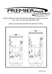
Matrix 424/832/832+
ICON & LCD User Manual
Software Version 5
EN50131-1
RINS915-2
Security Grade 2
Environmental Class 2
Matrix User Guide
CONTENTS
CHAPTER 1: INTRODUCTION............................................................................................... 1
CHAPTER 2: REPLACING THE BATTERIES........................................................................ 2
CHAPTER 3: DISPLAYS ........................................................................................................ 3
3.1 LAYOUT & KEY OPERATION ............................................................................................................3
3.2 ICON SYMBOL MEANINGS ................................................................................................................4
3.3 LCD SYMBOL MEANINGS ................................................................................................................5
3.4 PROXIMITY READER LED MEANINGS ...............................................................................................5
3.5 KEY FOB SYMBOLS AND MEANINGS (KF4DW).................................................................................6
3.5.1 The KF4DW Actions ...............................................................................................................6
3.5.2 STATUS LEDS .......................................................................................................................6
3.6 HIDDEN DISPLAY MODE ..................................................................................................................7
3.7 LATCHING ALARMS – DENMARK, NORWAY, FINLAND & SWEDEN ONLY ............................................7
3.8 ARM MODES – SINGLE PARTITION ...................................................................................................8
3.9 PARTITION INDICATIONS ..................................................................................................................9
3.9.1 LCD Keypad – Multiple Partitions ...........................................................................................9
3.9.2 Icon Keypad..........................................................................................................................10
3.10 DISPLAYING SYSTEM FAULTS ......................................................................................................12
3.10.1 Icon Keypad........................................................................................................................12
3.10.2 LCD Keypad .......................................................................................................................12
3.11 DISPLAYING OPEN ZONES ...........................................................................................................13
3.12 LATCHING SYSTEM FAULTS – NORWAY, DENMARK, FINLAND & SWEDEN .....................................13
3.13 LATCHING BATTERY FAULT .........................................................................................................13
3.14 ANTI-CODE / ENGINEER RESET ....................................................................................................13
CHAPTER 4: ARMING / DISARMING THE SYSTEM .......................................................... 14
4.1 ICON KEYPAD ...............................................................................................................................14
4.1.1 Arming – Single Partition User..............................................................................................14
4.1.2 Displaying the Armed Status ................................................................................................14
4.1.3 Disarming the System – Single Partition User ......................................................................14
4.1.4 Latched Alarm Condition – Denmark, Finland, Norway & Sweden Only ..............................15
4.1.5 Anti-Code Reset ...................................................................................................................15
4.1.6 Arming – Multiple Partition User ...........................................................................................16
4.1.7 Displaying the Armed Status – Multiple Partition User .........................................................16
4.1.8 Disarming the System – Multiple Partition User....................................................................16
4.1.9 Latched Alarm Condition – Denmark, Finland, Norway & Sweden Only – Multiple Partition17
4.1.10 Anti-Code Reset – Multiple Partition User ..........................................................................17
4.2 LCD KEYPAD ...............................................................................................................................18
4.2.1 Arming – Single Partition User..............................................................................................18
4.2.2 Displaying the Armed Status – Single Partition User............................................................18
4.2.3 Disarming – Single Partition User.........................................................................................18
4.2.4 Latched Alarm Indication – Denmark, Norway, Finland & Sweden only – Single Partition...19
4.2.5 Anti-Code Reset – Single Partition User...............................................................................19
4.2.6 Arming – Multiple Partition User ...........................................................................................19
4.2.7 Displaying the Armed Status – Multiple Partition User .........................................................20
4.2.8 Disarming – Multiple Partition User ......................................................................................20
4.2.9 Latched Alarm Indication – Denmark, Norway, Finland & Sweden only – Multiple Partition 21
4.2.10 Anti-Code Reset – Multiple Partition User ..........................................................................21
4.3 PARTITIONS ..................................................................................................................................22
4.3.1 Part Sets Explained ..............................................................................................................22
4.3.2 Partitions Explained ..............................................................................................................22
4.3.3 Partition Dependency ...........................................................................................................22
4.4 DURESS ARMING / DISARMING ......................................................................................................23
4.4.1 Entering a Duress Code .......................................................................................................23
RINS915-2
Page i
Matrix User Guide
4.5 FAULT TONES ...............................................................................................................................23
4.6 EMERGENCY SERVICES .................................................................................................................23
4.6.1 Activating a Fire Alarm..........................................................................................................23
4.6.2 Activating a Personal Attack (P.A) Alarm .............................................................................23
4.6.3 Activating a Medical Alarm ...................................................................................................23
CHAPTER 5: USER FUNCTIONS ........................................................................................ 24
5.1 AVAILABLE USER FUNCTIONS .......................................................................................................24
5.2 ENTERING USER MODE .................................................................................................................25
5.3 EXITING USER MODE ....................................................................................................................25
5.4 ARM WITH OMITS ..........................................................................................................................26
5.5 DISPLAY LOG ...............................................................................................................................27
5.6 SET VOLUME ................................................................................................................................28
5.7 SET BACKLIGHT ...........................................................................................................................29
5.8 VIEW TIME AND DATE ...................................................................................................................30
5.9 CHANGE TIME ...............................................................................................................................31
5.10 CHANGE DATE ............................................................................................................................32
5.11 CHANGING/DELETING USER CODES AND ATTRIBUTES – ICON KEYPAD ........................................33
5.11.1 Changing/Deleting a Code..................................................................................................33
5.11.2 Add/Delete/Change Users ..................................................................................................33
5.12 CHANGING USER CODES AND ATTRIBUTES – LCD KEYPAD .........................................................35
5.12.1 Changing a User Code .......................................................................................................35
5.12.2 Editing User Codes and Attributes......................................................................................36
5.13 EDITING USER NAME – LCD KEYPAD ONLY ................................................................................39
5.14 ADJUSTING THE PROXIMITY VOLUME ...........................................................................................41
5.15 ADDING/REMOVING PROXIMITY CARDS & TAGS ...........................................................................42
5.16 ADDING / REMOVING KEY FOBS ...................................................................................................43
5.17 PERFORMING AN NVM RESET ON A KEYFOB................................................................................44
5.18 SYSTEM TEST .............................................................................................................................45
5.19 ACTIVATING PGM FROM THE KEYPAD .........................................................................................45
5.20 UPLOAD/DOWNLOAD 1 HOUR WINDOW .......................................................................................46
5.21 ZONE TYPE DESCRIPTIONS .........................................................................................................47
CHAPTER 6: ZONE & PARTITION INDICATION TABLE ................................................... 48
CHAPTER 7: PROXIMITY READER .................................................................................... 49
7.1 INTRODUCTION.........................................................................................................................49
7.2 SINGLE PARTITION OPERATION .....................................................................................................49
7.2.1 Arming the Panel ..................................................................................................................49
7.2.2 Disarming the Panel .............................................................................................................50
7.3 MULTI-PARTITION OPERATION ......................................................................................................50
7.3.1 Arming the Panel ..................................................................................................................50
CHAPTER 8: THE KEYFOB................................................................................................. 51
8.1 INTRODUCTION .............................................................................................................................51
8.2 HOW TO USE THE KEYFOB .............................................................................................................51
8.3 STATUS LED ................................................................................................................................51
8.4 LOCKING A KEY FOB ....................................................................................................................51
CHAPTER 9: EVENT LOG TABLES.................................................................................... 52
9.1 ICON KEYPAD LOG TABLE ............................................................................................................52
9.2 LCD KEYPAD LOG TABLE .............................................................................................................54
9.3 VIEWING LOG AFTER A ZONE ALARM.............................................................................................56
Page ii
RINS915-2
Matrix User Guide
CHAPTER 1: INTRODUCTION
Thank you for buying the Matrix control panel, which uses the latest technology in design and manufacture. As
the end user of the Matrix security system, this manual has been written to help you use the many functions
available enabling you to get the best out of the Matrix alarm panel. Once you are familiar with the panel and its
functions, it is advisable to change the default Master User code.
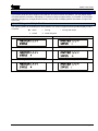
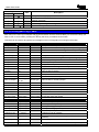
The system can be operated in the following modes from which different options are available to the end user:
Master and Limited User Functions
Master
Limited
User Function
Description
9
9
Arm with Omits
Allows zones to be omitted whilst arming the panel
9
9
Display Log
Allows you to view the event log
9
9
Set Volume
Allows you to alter the volume setting for your keypad
9
9
Set Backlight
Allows you to set the backlight intensity
9
9
View Time & Date
Allows you to view the panel’s time and date settings
9
8
Change Time
Allows you to change the alarm panel time
9
8
Change Date
Allows you to change the alarm panel date
9
8
Edit User
Allows you to edit user types/attributes
9
8
Change Codes
Allows you to change a users code only
9
8
Edit User Name
Allows you to edit user names
9
8
Proximity Volume
Allows you to change the volume of a proximity reader
9
8
Proximity Cards
Allows you to add/delete proximity cards
9
8
Add keyfob
Allows you to add/delete key fobs
9
8
Pulse PGM 1
Allows you to activate a PGM output
9
8
1 Hr Active
Allows you to open a 1hour up/download time window
9
8
System Test
Allows you to perform a minimal keypad/panel test
NOTE: There are no user serviceable parts inside.
Quick Start
To Arm / Disarm via ICON go to page 14
To Arm / Disarm via LCD go to page 18
To Arm / Disarm via Prox go to page 49
To Arm / Disarm via keyfob go to page 51
RINS915-2
Page 1
Matrix User Guide
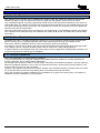
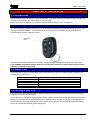
CHAPTER 2: REPLACING THE BATTERIES
The KX12DW, UT3DW and KF4DW will require there batteries to be changed at some point. As the batteries
are lithium ones extra care needs to be taken when removing/inserting batteries into the devices.
The batteries supplied have been chosen to provide long service life whilst, for safety reasons,
having limited output current.
Replace only with approved batteries.
To prevent possible damage to components, any static electrical charge on your body needs to be
eliminated before touching the inside of the unit. This can be accomplished by touching some
grounded/earthed metallic conductor such as a radiator/pipework immediately before replacing the
batteries.
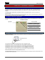
The KX12DW and UT3DW
8
8
9
Alarm
+
9
3.6 AA LITHIUM BATTERY
-
+
3.6 AA LITHIUM BATTERY
-
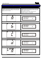
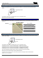
The KF4DW
CAUTION
Disposing Used Batteries
a) Ensure that you act in accordance with all applicable environmental regulations.
b) Do not open the battery or dispose of in a fire.
c) Small batteries can be attractive to small children and may be swallowed; take precautions.
d) Consult the information sheet supplied with the replacement battery
Page 2
RINS915-2
Matrix User Guide
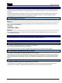
CHAPTER 3: DISPLAYS
3.1 Layout & Key Operation
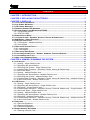
Icon Keypad
LCD Keypad
LL
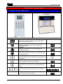
Button Meanings
Seven Segment Display
Shows zone numbers, partitions armed, system faults,
and event memory log number.
Personal Attack Alarm
Holding this button down for 2 seconds triggers an
immediate PA alarm.
Fire Alarm
Holding this button down for 2 seconds triggers an
immediate Fire alarm.
Medical button
Holding the medical button down for 2 seconds will trigger
an emergency alarm.
Numerical buttons
Functional buttons used for imputing user codes and user
programming.
Arm button
Used to change arm mode during exit delay
C
Function button
Used to enter / exit user mode and, save programming
options.
>@
Direction buttons
Direction keys are used to select options and view the
log.
Menu Button
Used to enter and exit menu mode.
RINS915-2
Page: 3
Matrix User Guide
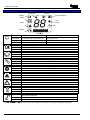
3.2 Icon Symbol Meanings
Disarmed
Armed
Supply
Personal Attack
Ready
Fire
Alarm
Fault
((
))
Tamper
Illuminated
Blinking
Extinguished
Illuminated
Blinking
Extinguished
Illuminated
Blinking
Extinguished
Illuminated
Blinking
Extinguished
Illuminated
Blinking
Extinguished
P1 P2 P3 P4
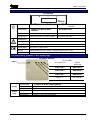
Partitions
Rest of World
Correct AC & DC power sources
DC source (battery) fault
No AC power supplied to the panel
Denmark, Norway, Finland & Sweden
AC power is OK
An AC fault
No power to panel
OK to Arm, no open zones
Select partitions to arm or disarm / Programming function is active
One or more open zones or all assigned partitions are already armed
Used in the Display Log function to qualify log information
Active alarm in FTA mode. Digit display shows active zone
No alarm active
Indicates a tamper condition (used in log display)
Indicates a tamper condition
No tamper alarm active
Indicates a PA alarm condition (used in log display)
Indicates a PA alarm condition
No PA active
Extinguished
Indicates a Fire alarm condition (used in log display)
Indicates a Fire alarm condition
No Fire alarm active
Illuminated
Indicates a system Fault
Illuminated
Blinking
Blinking
Extinguished
No Fault active
Illuminated
Extinguished
The panel is armed
The panel is arming with omitted zones
The panel is not armed
Illuminated
The panel is disarmed
Blinking
Blinking
Extinguished
The panel is not disarmed
The P1, P2, P3 and P4 icons are used to show partition information as well as the partition segments.
Page 4
RINS915-2
Matrix User Guide
3.3 LCD Symbol Meanings
LCD KEYPAD
OK
REST OF THE WORLD
Illuminated
DENMARK, NORWAY, FINLAND &
SWEDEN
CORRECT AC & DC POWER
AC POWER IS OK
SOURCES
Blinking
Indicates DC source (battery) fault
Indicates an AC fault
Extinguished
Indicates AC fault / no power to panel
No power to the panel
Illuminated
Indicates a system Fault
Blinking
Engineers mode active
Extinguished
No Fault active
Illuminated
OK to Arm, no open zones
Blinking
Select partitions to arm or disarm / Programming function is active
Extinguished
One or more open zones or all assigned partitions are already armed
3.4 Proximity Reader LED meanings
PROXIMITY READER
STATUS LEDS
Supply
MULTIPARTITION
SINGLE
PARTITION
PARTITION 4
ARM MODE D
PARTITION 3
ARM MODE C
PARTITION 2
ARM MODE B
Partition 1
Illuminated
Supply
Status
LEDs
RINS915-2
Blinking
Extinguished
Illuminated
Blinking
Extinguished
Arm mode A
CORRECT AC & DC POWER SOURCES
Indicates DC source (battery) fault
Indicates AC fault / no power to panel
PARTITION OR ARM MODE IS ARMED
Partition or Arm mode is in Alarm
Partition or Arm mode is Disarmed
Page: 5
Matrix User Guide
3.5 Key fob Symbols and Meanings (KF4DW)
Status LED
LOCK Button
(Button 1)
I Button
(Button 3)
UNLOCK Button
(Button 2)
II Button
(Button 4)
3.5.1 The KF4DW Actions
Action
Arm Mode A
Arm Mode B
Arm Mode C
Arm Mode D
Disarm
RKP Controlled Output
Keyfob Controlled Output
Fire Alarm
Medical Alarm
Personal Attack
Not Used
Quick Arm Mode A
Quick Arm Mode B
Quick Arm Mode C
Quick Arm Mode D
Description
Arm the panel in Arm Mode A
Arm the panel in Arm Mode B
Arm the panel in Arm Mode C
Arm the panel in Arm Mode D
Disarm the panel (if currently armed or in First to Alarm)
RKP controlled output*
Keyfob controlled output*
Creates a Fire Alarm
Creates a Medical Alarm
Creates a Personal Attack
No Action
Quick arm part set A**
Quick arm part set B**
Quick arm part set C**
Quick arm part set D**
*Note 1: Key fob Controlled is a new programmable output type that can be only be assigned to key fob button
presses.
*Note 2: Quick arm is a new arming method. It does not display open zones whilst arming.
All programmed button actions are on a per partition basis. This means that Partitions 1, 2, 3 & 4 can have
totally different sets of button actions from each other. This also means that key fobs assigned to users will only
be active in one partition (the first partition if assigned to multiple partitions).
3.5.2 STATUS LEDS
The status LED on the key fob shows the status of the panel when any arm or disarm button is pressed. The
indications are shown below:
Panel Status
LED Indication
Green for 3 seconds
Disarmed
Toggles Green/Red in 3 second bursts until armed
Arming
Red for 3 seconds
Armed
Flashing Green for 3 seconds
In Alarm
Flashing Green for 3 seconds
In FTA (First To Alarm)
Page 6
RINS915-2
Matrix User Guide
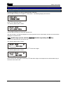
3.6 Hidden Display Mode
The Matrix alarm panel incorporates a hidden display (confidential mode) feature that can be enabled / disabled
by your installation engineer.
This feature hides all of the panel information from the keypad display if the keypad has not been used for the
last 20 seconds. In hidden display only the supply icon will be shown on the Icon keypad, and only the time &
date and supply LED will be displayed on the LCD keypad.
The keypad will remain in hidden display mode until a valid user code has been entered on the keypad.
Depending in which state the alarm panel is currently in, the first valid user code entry whilst in hidden display
mode will have the following effects on the panel.
When Disarmed
If there are no system faults then the panel will come out of hidden display mode and automatically start the
arming process.
If there are any system faults pending then the keypad will drop out of hidden display mode and allow the
system fault to display. The panel will not start the arming process until you re-enter your user code again.
When Armed
The panel will leave hidden display mode and start the disarm process.
For single partition keypad / user combinations this will result in a full panel disarm.
When In Alarm
The panel leave hidden display mode and drop into First To Alarm (FTA) mode.
When In First To Alarm (FTA) mode
If the keypad is allowed to drop back into hidden display mode whilst in FTA mode, then simply enter your user
code again to re-display the FTA information.
NOTE: When in User Menu mode the keypad will drop out of the user menu and then into
hidden display mode if no keys are pressed for 20 seconds. As long as a key is pressed at
least once every 20 seconds then user mode will remain active. Care must be taken not to
keep pressing invalid keystrokes as this may cause the alarm panel to interpret this as a
key tamper attempt and force the panel into a tamper alarm.
3.7
Latching Alarms – Denmark, Norway, Finland & Sweden only
After each and every alarm event the panel will display a latched alarm indicator, until you reset the latched
alarm yourself, by either viewing the event log or by re-arming the panel.
Latched alarms are only displayed in day mode and are indicated by a fast flashing bell on the Icon keypad and
by the message VIEW THE LOG on the LCD keypad.
To clear the latched alarm indicator, you can either view the event log using the View Log user function, or
alternatively by fully re-arming the panel again.
If hidden display mode is enabled the keypad will not hide until the latched alarm is cleared.
RINS915-2
Page: 7
Matrix User Guide
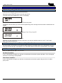
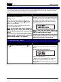
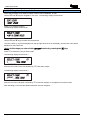
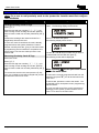
3.8 Arm Modes – Single Partition
Icon Keypad
LCD Keypad
If a keypad is allocated to only one of the four
available partitions then the arm mode in which this
partition is armed will be displayed, assuming hidden
display mode is not active.
If a keypad is allocated to only one of the four
available partitions then the arm mode in which this
partition is armed will be displayed, assuming hidden
display mode is not active.
Alternatively, the arm mode message may be
displayed if enable by your Engineer.
Partition is armed in Mode A
TIME/DATE
ARM MODE
A
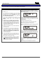
Partition is armed in Mode B
TIME/DATE
ARM MODE
B
Partition is armed in Mode C
TIME/DATE
ARM MODE
C
Partition is armed in Mode D
TIME/DATE
ARM MODE
D
Partition is arming with Omits
TIME/DATE
ARM MODE
Page 8
!A
RINS915-2
Matrix User Guide
3.9 Partition Indications
If your alarm panel has been configured at install time to have more than one partition, you may display single
or multiple partition information, depending on a variety of options programmed by your installer. If your keypad
has been configured for a single partition use only, then you will not display partition information, except in anti
code reset.
3.9.1 LCD Keypad – Multiple Partitions
The following status will be displayed for each partition of a common keypad, assuming hidden display mode is
not active:
! Arming With Omits
I Alarm
% Arming
&
Armed
#
Reset Required
All partitions are disarmed
Partition 1 is arming or selected to be armed
Partition 1 is armed
Partition 1 in alarm condition
Partition 1 Engineer / Anti-code reset required
Partition 1 arming with omits
RINS915-2
Page: 9
Matrix User Guide
3.9.2 Icon Keypad
As well as the P1 – P4 icons, partition information is shown on the 7-segment displays, as this is easily visible
from a distance. Each of the two corner segments are assigned to a partition as shown below.
Partition 1
Partition 2
Partition 3
Partition 4
P1 P2 P3 P4
Single Partition Indications
The following displays are shown on the Icon keypad when the keypad is used to arm or disarm the panel when
configured as a single-partition system.
Disarmed
In Alarm
The DISARMED and
OK icons are
displayed.
The panel is ready for
arming.
Arming
The last open zone
number is displayed.
(Zone 1)
First To Alarm (FTA)
The DISARMED and
OK icons are
displayed.
The panel is arming in
arm mode A
Armed
The BELL icon
flashes.
((
))
Zone 1 was the First
zone To Alarm (FTA)
Arming with Omits
The ARMED icon is
displayed.
The armed icon
flashes indicating
that the panel is
arming with omitted
zones.
The panel has armed
in mode A
Anti-Code Reset / Engineer Reset
((
((
))
))
Partition 1 segments flash
alternately as shown.
P1
Page 10
RINS915-2
Matrix User Guide
Multiple Partition Indications
The following displays are shown when the keypad is used to arm or disarm the panel when configured as a
multi-partition system.
Please note that if you have a multi-partition installation, your keypad and user code may have been configured
for single partition operation only. If this is the case then please refer to single partition operation throughout this
manual.
Icon Keypad
Disarmed
In Alarm
The DISARMED and
OK icons are displayed.
The panel is ready for
arming.
Choose Partitions
The last open zone
number is displayed.
(Zone 1)
Choose FTA
OK icon flashes to
prompt you to enter the
partition(s) you want to
arm.
Arming
The OK icon flashes.
Partition in alarm
flashes.
First To Alarm (FTA)
OK stops flashing.
Arming partitions 1, 2 &
3 flash.
(
)
P1 P2 P3
The BELL icon
flashes.
The first zone into
alarm in the partition
is displayed
Armed
The ARMED icon is
displayed.
Partitions 1, 2, & 3 are
armed.
P1 P2 P3
Anti-Code Reset / Engineer Reset
((
((
))
))
Partition segments flash
alternately as shown.
P1
RINS915-2
Page: 11
Matrix User Guide
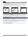
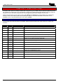
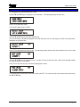
3.10 Displaying System Faults
3.10.1 Icon Keypad
When the Matrix detects a system fault, it displays the fault on the icon keypad (â). The fault takes the form of
a special symbol and a number. You can use this number to look up the actual fault by using the log table on
page 52. The system fault section of the log table has been repeated here for your convenience.
Example: System Fault 7
Fault number
System Fault symbol
Fault icon
When a system fault is displayed in day mode, the following table applies.
System Fault
Description
1
Bell fuse fail
2
Auxiliary fuse fail
3
Battery missing
4
Battery low voltage
5
Mains fail
6
Telephone line fail
7
Remote device has gone missing
8
Failed to report to central station
9
Battery fault on wireless expander
A
Battery fault on keyfob(s)
B
Jamming fault on wireless expander
C
Detector signal low
D
Detector signal has gone missing
Icon
â
â
â
â
â
â
â
â
â
â
â
â
â
While system faults are being displayed the keypad sounder periodically emits a low tone. This is to alert you to
the fault. Once you are aware of the fault you can silence the low tones by pressing the
key once while the
fault is being displayed. If the fault is not cleared for a period of time then the sounder will re-start.
In hidden display mode the fault sounder cannot be silenced.
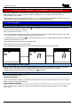
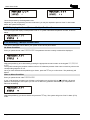
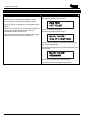
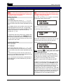
3.10.2 LCD Keypad
On an LCD keypad the system fault is automatically displayed on the display as shown below:
TIME/DATE
!BATTERY MISSING
While system faults are being displayed the keypad sounder periodically emits a low tone. This is to alert you to
the fault. Once you are aware of the fault you can silence the low tones by pressing the key once while the
fault is being displayed. If the fault is not cleared for a period of time then the sounder will re-start.
In hidden display mode the fault sounder cannot be silenced.
Note: If the keypad has entered hidden display mode, only the time and date will be
displayed.
Page 12
RINS915-2
Matrix User Guide
3.11 Displaying Open Zones
While the panel is disarmed, any open zones will be displayed on the keypad (zone number on 7-segment
display on Icon keypad, zone name preceded by the ‘!’ symbol on LCD keypad), as long as this feature has
been enabled by your installer. Since the keypad can only display one open zone at a time, use the > and ?
keys to display other open zones.
3.12 Latching System Faults – Norway, Denmark, Finland &
Sweden
All system faults are latched. This means that once a system fault has been triggered, the display will continue
to display the fault even if the fault is eventually removed from the system. To clear the latched fault, first
remove the fault then view the event log.
Once you have entered and then left the View Log function, and if the system fault is no longer active, the
system fault message and the VIEW THE LOG indication will be removed from the display.
3.13 Latching Battery Fault
Battery faults may be latched if enabled by your installation engineer. This means that once a battery fault has
occurred, the display will continue to display the fault even if the cause of the fault has been removed from the
system.
In this case you will need to contact your installation engineer to clear the battery fault from the display.
If your installation engineer has allowed you to reset battery faults, then the Latching System Faults procedure
above will allow you to clear the fault as discussed.
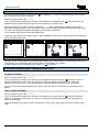
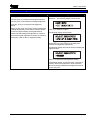
3.14 Anti-code / Engineer Reset
If your installer has enabled anti-code or Engineer reset, after an alarm condition you will be unable to re-arm
the panel until a reset code has been entered.
Icon Keypad
((
))
((
))
P1
LCD Keypad
Single Partition
Multiple Partitions
Press the C key to display the anti-code seed number. This should be passed on to your central monitoring
station, who will in turn provide you with a corresponding reset code.
Enter the code on your keypad.
The system will return to normal operation.
RINS915-2
Page: 13
Matrix User Guide
CHAPTER 4: ARMING / DISARMING THE SYSTEM
This section details how to arm and disarm a Matrix system using both the Icon and LCD keypads. As with most
Matrix features there are always possible variations depending on how the Matrix features have been
programmed by your installer.
These instructions assume the default user code ( TUV) is being used to arm/disarm the panel. If your user
code is different, then substitute your user code in place of the one described here.
4.1 Icon Keypad
4.1.1 Arming – Single Partition User
To arm the system all zones must be closed (y icon displayed). To arm the system with open zones, refer to
the Arm With Omits function on page 26.
Enter you personal user code
TUV.
If your code has been accepted, you will hear a confirmation tone and the system will start arming in arm mode
A. The exit tones will sound indicating that arming has commenced.
To change the arm mode press the C key followed by the arm mode you require (A, B, C or D). The system will
re-configure for the new arm mode.
You must leave the premises by the designated route.
At the end of the exit timer the system will arm.
Some installations require that a push button switch be pressed before the panel finally arms.
Disarmed
Arming
Armed
4.1.2 Displaying the Armed Status
Once the system has armed, the Icon keypad will either display the arm mode (A, B, C or D), or it will display
nothing at all. This depends on how the Matrix features have been programmed by your installer.
If hidden display mode is enabled only the supply icon ({) will operate.
4.1.3 Disarming the System – Single Partition User
Enter you personal user code
TUV.
No Alarm Condition
If your code has been accepted, you will hear a confirmation tone and the system will disarm. The Icon keypad
will revert to normal day mode operation.
After an Alarm Condition
If your code has been accepted, you will hear a confirmation tone and the system will go into First To Alarm
(FTA) mode.
Page 14
RINS915-2
Matrix User Guide
First To Alarm (FTA) Mode
The bell icon (z) flashes slowly indicating that you are in FTA mode. This mode allows you to view the first
zone that went into, and thus caused, the alarm. If the keypad enters hidden display mode whilst in FTA mode,
simply re-enter your user code to re-display the FTA information.
To fully disarm, enter you personal user code TUV. If your code has been accepted, you will hear a
confirmation tone and the system will disarm. The ICON keypad display will revert to normal day mode
operation.
Alarm (Zone 1)
FTA (Zone 1)
((
Disarmed
))
4.1.4 Latched Alarm Condition – Denmark, Finland, Norway & Sweden Only
A special indication will appear on the ICON display after any valid alarm has been successfully disarmed. The
ICON keypad will flash the bell icon (z) at twice the normal rate. Whilst this display is active, the keypad will not
enter hidden display mode (if hidden display mode is enabled).
This is to prompt you to check the event log. To stop the bell icon (z) flashing you must use the user function
View Log described on page 27. Alternatively, enter a valid user code to re-arm the panel. Once armed, the
previous latched alarm will be cleared.
4.1.5 Anti-Code Reset
If your system has anti code reset enabled, the top left partition segments will flash alternately. The P1 icon will
also flash, indicating that partition 1 is in anti-code reset.
You will be unable to re-arm your alarm panel until an anti-code number has been entered. Press the C key to
display the anti code seed number. The number is displayed one digit at a time. This number should be passed
onto your central monitoring station, who will in turn provide you with a corresponding anti code number.
Enter this anti code number on your keypad (after pressing the C key).
Your system will return to normal operation.
If the keypad drops into hidden display mode, re-enter your user code to unhide the display and press the C
key to re-display the anti-code seed number.
RINS915-2
Page: 15
Matrix User Guide
4.1.6 Arming – Multiple Partition User
To arm the system all zones must be closed, (y icon displayed). To arm the system with open zones, refer to
the Arm With Omits function on page 26.
Enter you personal user code
TUV.
If your code has been accepted you will hear a confirmation tone and the OK icon (y) will start to flash. This
indicates that you should enter the number(s) of the partition(s) you wish to arm.
Enter the partition(s) you wish to arm by pressing the
- V keys on the keypad. Partitions that you have
selected for arming will flash on the icon display. When you have made your final selection(s) press the
key
to confirm. The exit tones will sound indicating that arming has commenced.
You must leave the premises by the designated route.
At the end of the exit timer the system will arm. Some installations require that a push button switch be pressed
before the panel finally arms.
Disarmed
Select Partitions
Arming
Armed
P1 P2 P3
P1 P2 P3
4.1.7 Displaying the Armed Status – Multiple Partition User
Once the system is armed the icon keypad will either display the armed partitions or it will display nothing at all.
This depends on how the Matrix features have been programmed by your installer.
If hidden display mode is enabled only the supply icon ({) will operate.
4.1.8 Disarming the System – Multiple Partition User
This section describes how to disarm your system under various panel states.
No Alarm Condition
Enter you personal user code
TUV.
If your code has been accepted, you will hear a confirmation tone and the OK icon (y) will flash. All armed
partitions are displayed. At this point you can arm or disarm any partitions allocated to you. Select the
partition(s) you wish to disarm. The selected partition segments will be removed from the icon display.
Once you have selected all the partition(s) to disarm, press the
disarm.
key to confirm them. The partition(s) will
After an Alarm Condition
Enter you personal user code
TUV.
If your code has been accepted you will hear a confirmation tone and the OK icon (y) will flash. All armed
partitions are displayed. At this point you can arm or disarm any partitions allocated to you. All partitions in
alarm will be flashing.
Select the partition(s) you wish to disarm and press the
mode.
Page 16
key. The system will go into First To Alarm (FTA)
RINS915-2
Matrix User Guide
First To Alarm (FTA) Mode
The bell icon (z) flashes slowly indicating that you are in FTA mode.
This mode allows you to view the first zone that went into, and thus caused, the alarm. This will always be for
the last partition you selected. If the keypad enters hidden display mode whilst in FTA mode, simply re-enter
your code to re-display the FTA information.
To disarm the partition(s), enter your personal user code
disarm, followed by the
key to confirm.
TUV and select the partition(s) you want to
The selected partitions will disarm.
In Alarm (Zone 1)
Choose FTA
FTA (Zone 1)
((
Disarmed
))
4.1.9 Latched Alarm Condition – Denmark, Finland, Norway & Sweden Only – Multiple
Partition
A special indication will appear on the ICON display after any valid alarm has been successfully disarmed. The
ICON keypad will flash the bell icon (z) at twice the normal rate. Whilst this display is active, the keypad will not
enter hidden display mode (if hidden display mode is enabled).
This is to prompt you to check the event log. To stop the bell icon (z) flashing you must use the user function
View Log described on page 27. Alternatively, enter a valid user code to re-arm the panel. Once armed, the
previous latched alarm will be cleared.
4.1.10 Anti-Code Reset – Multiple Partition User
If your system has anti code reset enabled, the two segments of the corner partition segment for the partition in
question will flash alternately. The partition icon will also flash, indicating that the partition is in anti-code reset.
You will be unable to re-arm your alarm panel until an anti-code number has been entered. Press the C key to
display the anti code seed number. The number is displayed one digit at a time. This number should be passed
onto your central monitoring station, who will in turn provide you with a corresponding anti code number.
Enter this anti code number on your keypad (after pressing the C key).
Your system will return to normal operation.
If the keypad drops into hidden display mode, re-enter your user code to unhide the display and press the C
key to re-display the anti-code seed number.
RINS915-2
Page: 17
Matrix User Guide
4.2 LCD Keypad
4.2.1 Arming – Single Partition User
If all zones are closed the OK LED will be illuminated.
Otherwise use the & buttons to list the open zones.
The open zones will be displayed in order on the display:
Enter you personal user code to arm the panel.
The partition will start arming in mode A and a repeated high tone counting the exit time will be emitted from the
keypad.
If a different Arm Mode is desired press then or or or .
TIME/DATE
ARM MODE
B
Leave the premises by the designated route.
Depending on the programming and arm mode used, you may be required to press a ‘Push To Set’ button
before the system will fully arm.
4.2.2 Displaying the Armed Status – Single Partition User
Once the system is armed the LCD keypad will either display the time/date and the arm mode (A, B, C or D) or
it will just the time and date. This depends on how the Matrix features have been programmed by your installer.
4.2.3 Disarming – Single Partition User
Enter you personal user code .
No Alarm Condition
If your code has been accepted, you will hear a confirmation tone and the system will disarm. The LCD keypad
will revert to normal day mode operation.
After Alarm Condition
If your code has been accepted, you will hear a confirmation tone and the system will go into First To Alarm
(FTA) mode.
Page 18
RINS915-2
Matrix User Guide
First To Alarm (FTA) Mode
The first zone to activate an alarm will be shown on the display.
ALARM
ZONE 1
To clear the display and returned to disarmed mode enter the user code again.
If the keypad goes into Hidden Display mode whilst you are in FTA mode, enter your user code again to redisplay the FTA messages.
4.2.4 Latched Alarm Indication – Denmark, Norway, Finland & Sweden only – Single
Partition
A special indication will appear on the LCD display after any valid alarm has been successfully disarmed. The
LCD keypad will display VIEW THE LOG. Whilst this display is active, the keypad will not enter hidden display mode
(if hidden display mode is enabled).
This is to prompt you to check the event log. To remove the latched alarm you must use the user function View
Log described on page 27. Alternatively, enter a valid user code to re-arm the panel. Once armed, the previous
latched alarm will be cleared.
4.2.5 Anti-Code Reset – Single Partition User
If your system has anti code reset enabled, the LCD display will show ‘RESET REQUIRED’.
You will be unable to re-arm your alarm panel until an anti-code number has been entered. Press the C key to
display the anti code seed number. This number should be passed onto your central monitoring station, who will
in turn provide you with a corresponding anti code number.
Enter this anti code number on your keypad (after pressing the C key).
Your system will return to normal operation.
If the keypad drops into hidden display mode, re-enter your user code to unhide the display and press the C
key to re-display the anti-code seed number.
4.2.6 Arming – Multiple Partition User
If all zones are closed the OK LED will be illuminated.
Otherwise use the & buttons to list the open zones.
The open zones will be displayed in order on the display:
Enter you personal user code to arm the panel.
Select the partition(s) to be armed by entering the appropriate numeric button on the keypad: , , or
.
The LCD display will indicate the partitions to arm with an “%” symbol
Alternate presses of the same numeric key will turn the corresponding symbol on / off.
Select all partitions needed to arm and then press to confirm.
Arming will be confirmed by a repeated high tone emitted from the keypad.
Armed partitions are identified by a “&” symbol.
RINS915-2
Page: 19
Matrix User Guide
Arming Partition 1
Arming Partitions 1 & 2
Leave the premises by the designated route.
Depending on the programming and arm mode used, you may be required to press a ‘Push To Set’ button
before the system will fully arm.
4.2.7 Displaying the Armed Status – Multiple Partition User
The LCD keypad will display armed partitions with a “&” symbol underneath the partition number, as shown
below.
4.2.8 Disarming – Multiple Partition User
This section describes how to disarm your system under various panel states.
No Alarm Condition
Enter you personal user code . The partitions that are currently armed will be displayed:
Select the partition(s) to be disarmed by pressing the appropriate numeric button on the keypad: , , or .
The symbol indicating the partition to disarm will turn off. Alternate presses of the same numeric key will turn the
corresponding segment on / off.
Once you have selected all the partition(s) to disarm, press the key to confirm them. The partition(s) will
disarm.
After an Alarm Condition
Enter you personal user code .
If your code has been accepted you will hear a confirmation tone and the OK icon (y) will flash. All armed
partitions are displayed. At this point you can arm or disarm any partitions allocated to you. All partitions in
alarm will be flashing.
Select the partition(s) you wish to disarm and press the key. The system will go into First To Alarm (FTA)
mode.
Page 20
RINS915-2
Matrix User Guide
First To Alarm (FTA) Mode
The first zone to activate an alarm will be shown on the display.
To clear the display and returned to disarmed mode enter the user code again.
If the keypad goes into Hidden Display mode whilst you are in FTA mode, enter your user code again to redisplay the FTA messages.
4.2.9 Latched Alarm Indication – Denmark, Norway, Finland & Sweden only – Multiple
Partition
A special indication will appear on the LCD display after any valid alarm has been successfully disarmed. The
LCD keypad will display VIEW THE LOG. Whilst this display is active, the keypad will not enter hidden display mode
(if hidden display mode is enabled).
This is to prompt you to check the event log. To remove the latched alarm you must use the user function View
Log described on page 27. Alternatively, enter a valid user code to re-arm the panel. Once armed, the previous
latched alarm will be cleared.
4.2.10 Anti-Code Reset – Multiple Partition User
If your system has anti code reset enabled, the LCD display will show the partitions that require anti-code reset
as shown below.
You will be unable to re-arm your alarm panel until an anti-code number has been entered. Press the key
to display the anti code seed number. This number should be passed onto your central monitoring station, who
will in turn provide you with a corresponding anti code number.
Enter this anti code number on your keypad (after pressing the key).
Your system will return to normal operation.
If the keypad drops into hidden display mode, re-enter your user code to unhide the display and press the key to re-display the anti-code seed number.
RINS915-2
Page: 21
Matrix User Guide
4.3 Partitions
4.3.1 Part Sets Explained
Each partition can be armed in one of 4 different arm modes. These arm modes are called part sets and are
identified as A, B, C or D. The default arm mode for single and multi partition systems is arm mode A.
Your installation engineer may have programmed certain zones so that they behave differently in the other arm
modes (B, C & D). For example, the panel might be programmed so that arming in arm mode B causes the rear
entry door and side gate to be un-protected. You might want to do this if you are working in the rear garden but
want the rest of the house protected.
Part sets in effect allow zones to be re-configured to your requirements. Your installation engineer can program
up to 4 different zone settings through the 4 different arm modes, A, B, C & D. The default arm mode is always
arm mode A.
4.3.2 Partitions Explained
The Matrix 832 / 832+ / 424 alarm panels have support for up to four partitions. Partitions allow a single alarm
panel to monitor up to 4 completely separate areas, each area having its own set of monitored zones.
This can be useful in installations where access to some areas needs to be restricted.
For example, you may wish to disarm one area of the protected premises while leaving other areas fully armed.
Your installer is able to configure the Matrix alarm panel to achieve this, using multiple partitions.
If multiple partitions are not required then the matrix system can be configured for single partition operation. This
is the most popular and common type of installation.
4.3.3 Partition Dependency
This is only applicable to a multiple partition installation.
In some circumstances you may wish a partition to arm/disarm based on whether or not other partitions are
armed or disarmed. This is called partition dependency.
An example of this would be a lobby in a block of flats. If the lobby was installed as partition 3 and two adjoining
flats were installed as partitions 1 and 2, then we could want the lobby to be armed only if both partitions 1 and
2 were armed, but not if only one was armed.
Similarly, if all 3 partitions are armed in the above example, we would want partition 3 to disarm when we disarm
any of the other flats (so that someone walking about in the lobby doesn’t trip the alarm).
Due to the complexity of partition installations it is advisable that you gain some training from your installer on
installation and use of partitions for your premises.
Page 22
RINS915-2
Matrix User Guide
4.4 Duress Arming / Disarming
A duress code is a personal user code that the alarm panel recognises as being entered under duress. By this
we mean that the user has been forcibly made to enter their user code to disarm or arm the panel by another
person(s).
The alarm panel treats this code like a proper user code and behaves as normal. The duress code will arm or
disarm the system as normal. However, an emergency message is sent to your central monitoring station
indicating that the panel was armed / disarmed under duress.
4.4.1 Entering a Duress Code
There are two methods for entering a duress code, which can be individually enabled or disabled.
Method 1
If your user code has different 3rd and 4th digits then simply reversing these digits on code entry, will cause a
duress code to be recognised.
Example
USER CODE: 123456
DURESS CODE: 124356
Method 2
The second method employs a special duress user code. This code is allocated either by a master user or by
your installation engineer.
4.5 Fault Tones
To silence fault tones, which occur while a fault is present, press the B key once.
4.6 Emergency Services
4.6.1 Activating a Fire Alarm
To activate the Fire Alarm hold down the ù button for 2 seconds.
The Fire alarm activates internal and external sirens.
Three rising tones will be heard, and a message will be sent to the to the central monitoring station.
4.6.2 Activating a Personal Attack (P.A) Alarm
To activate a Personal Attack hold down the û button for 2 seconds.
The PA alarm can be silent or audible depending on how the system has been programmed by your engineer. If
audible the internal and external sirens will be activated after pressing the button, a PA alarm message will be
sent to the central monitoring station. If silent, only a PA alarm message will be sent to the central monitoring
station
4.6.3 Activating a Medical Alarm
To activate the medical key hold down the ü button for 2 seconds
The Medical alarm will activate the internal and external sirens, and a high frequency repeated tone will be
emitted from the keypads. A medical alarm message will be sent to the central monitoring station.
RINS915-2
Page: 23
Matrix User Guide
CHAPTER 5: USER FUNCTIONS
The Matrix alarm panel is normally installed and configured by your installer using a special programming mode
not available to normal users. You can however configure some basic features and program new user codes by
using user mode. This section describes all of the programming functions available in user mode.
Please note that there are two types of user codes: Master and limited user codes. Master user codes have
access to more user mode functions than limited user codes. If a function described in this section is not
available to you, it may be because your user code is limited.
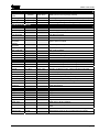
5.1 Available User Functions
The following user mode functions are available. Please note that limited user codes cannot run master only
functions.
Master
Limited
9
9
Arm with Omits
Allows zones to be omitted whilst arming the panel
9
9
Display Log
Allows you to view the event log
9
9
Set Volume
Allows you to alter the volume setting for your keypad
9
9
Set Backlight
Allows you to set the backlight intensity
9
9
View Time & Date
Allows you to view the panel’s time and date settings
9
8
Change Time
Allows you to change the alarm panel time
9
8
Change Date
Allows you to change the alarm panel date
9
8
Edit User
Allows you to edit user types/attributes
9
8
Change Codes
Allows you to change a users code only
9
8
Edit User Name
Allows you to edit user names
9
8
Proximity Volume
Allows you to change the volume of a proximity reader
9
8
Proximity Cards
Allows you to add/delete proximity cards
9
8
Add keyfob
Allows you to add/delete key fobs
9
8
Pulse PGM 1
Allows you to activate a PGM output
9
8
1 Hr Active
Allows you to open a 1hour up/download time window
9
8
System Test
Allows you to perform a minimal keypad/panel test
Page 24
User Function
Description
RINS915-2
Matrix User Guide
5.2 Entering User Mode
For functions such as viewing the log, changing user codes and changing the time etc. you must first enter user
mode. If hidden display mode is enabled, you must exit this before entering user mode. This ensures system
information cannot be changed or viewed by unauthorised users.
Icon Keypad
You can only enter user mode if one or more of your
assigned partitions are disarmed.
Enter
TUV
If your code has been accepted you will hear a
confirmation tone, the disarmed icon (ã) will flash
and the OK icon (y) will extinguish. This indicates
that you are in user mode.
LCD Keypad
To enter User mode press once and enter your
user code . If you do not wish to enter
the user menu, press the key again. Pressing this
key multiple times toggles entry to the user menu.
An acceptance tone will be heard and the following
display will be shown:
Once in user mode you can select the user mode
functions as described below.
Note: If you enter user mode and fail to
press any key for a while, user mode will Note: If you enter user mode and use no
expire and the keypad will return to day functions, the panel will automatically
mode.
time out and exit the user menu.
This timeout period is 20 seconds if hidden The time out period is 20 seconds if hidden
display mode is enabled and 2 minutes if display mode is enabled, and 2 minutes if
hidden display mode is not enabled.
hidden display mode is not enabled.
5.3 Exiting User Mode
Icon Keypad
To exit the User mode, press
. The disarmed
icon (ã) will stop flashing and the OK icon (y) will
re-appear.
LCD Keypad
There are two methods of exiting user mode:
1. Scroll to the end of the main user menu using the
key.
The following screen will be displayed:
Press to exit user menu
2. Whilst in user menu hold the key down for 2
seconds, which automatically exits user mode.
However this does not work whilst you are inside a
user function.
RINS915-2
Page: 25
Matrix User Guide
5.4 Arm with Omits
This function allows you to omit any zone(s) before arming the panel.
Icon Keypad
1. Enter user mode
2. Enter
T
LCD Keypad
Use the and keys to navigate to “ARM WITH
OMITS”, press to select the function. The following
display will be shown:
Two underscores will appear on the icon display
prompting you to enter a two digit zone number.
For single digit zone numbers ( 1-9 ), type the
zone number preceded by a ‘0’.
If you want to change the zone number you just
typed in, simply type a new two digit zone
number.
3. Press the
key to add this zone to the list of
zones to omit. If you have access to that zone
then an acceptance tone will sound. If you do
not have access to that zone a low error tone
will sound indicating that the zone was not
added to the zones to omit list.
Use the and keys to scroll through all the
available zones, or enter the two-digit zone number
on the keypad.
To omit the zone press key.
If you wish to leave the `Arm with omits’ option
without arming press the key twice.
To omit all selected zones and arm, press the key.
4. Repeat this operation for any more zones that
you want to omit.
5. If you decide not to arm with the omitted zones,
press the
key again. A low error tone will be
played. This indicates that all omitted zones
have been removed from the omit zone list. The
function will terminate.
Enter or to select the Arm mode.
A single partition keypad will start arming in the arm
mode chosen as in the example below (mode B).
6. If you are ready to arm the panel with the
omitted zones, press the C key followed by A,
B, C or D to choose an arm mode.
7. The panel will commence arming as normal
with all selected zones omitted. The armed icon
(í) will flash whilst arming to indicate that one
or more zones are omitted.
A multiple partition keypad will ask for a partition
number to arm. Select the partition and press to
confirm.
Upon arming, the omit indicator is removed.
Page 26
RINS915-2
Matrix User Guide
5.5 Display Log
Icon Keypad
Enter
LCD Keypad
Use the and keys to navigate to “DISPLAY LOG”.
The following display will be shown:
U
The last log entry will be displayed.
To view older events press the ? key on your
keypad.
To view newer events press the > key on your
keypad.
To exit the event log viewer press the
key.
When the start or end of the log has been reached,
two underscores are displayed on the icon keypad
display (vv)
The event log has a lot of information stored in it. To
fully convey that information special symbols and
display methods have been used. To understand the
log display you will need to refer to the log table
shown on page 52.
Please note that some log entries may be hidden
from you if your user code does not allow you to view
them.
Denmark, Norway, Finland & Sweden only
Viewing the event log clears the latched alarms
indication
Press to select this option.
To view older events, use the key or the key
for newer events.
If you wish to see additional data for an event press
the key.
Note: Some events don’t have additional
data
Pressing the key will return you to the event type
again.
Alternatively press the or key to scroll
through the next / proceeding events.
Press to leave the log.
Please refer to the log table to understand all the
information presented in this log option.
Viewing the event log clears the “VIEW THE LOG”
message prompt.
RINS915-2
Page: 27
Matrix User Guide
5.6 Set Volume
Icon Keypad
Enter
V
Use the > key to increase the speaker volume.
LCD Keypad
Use the and keys to navigate to “SET VOLUME”.
The following display will be shown:
Use the ? key to decrease the speaker volume.
Press the
setting.
key to accept your new keypad volume
Whilst you are using the > and ? keys to adjust the
volume, the keypad will emit a tone. This is to
indicate the current volume level.
Press to select this option.
The following display will be shown:
Please note that during alarm conditions the keypad
volume will be temporarily set to maximum.
Use the and keys to increase and decrease
the volume respectively.
The following display will now be shown indicating the
volume level:
Press to store the new volume setting.
The volume will be overridden during alarms.
Page 28
RINS915-2
Matrix User Guide
5.7 Set Backlight
Icon Keypad
Enter
W
Use the > key to increase the backlight brightness.
LCD Keypad
Use the and keys to navigate to “SET
BRIGHTNESS”. The following display will be shown:
Use the ? key to decrease the backlight brightness.
Press the
setting.
key to accept the new brightness
Whilst you are using the > and ? keys to adjust the
backlight brightness you are able to view the results
on the icon keypad display and keypad buttons.
Press to select this option.
The following display will be shown:
Please note that setting the brightness to maximum
causes the keypad brightness to remain at maximum
at all times. It will not dim on keypad inactivity.
Use the key or the key to increase and
decrease the brightness respectively.
The following display will now be shown indicating the
brightness level:
Press to store the new brightness setting.
The backlight will dim to minimum after 2 minutes of
inactivity unless the brightness is set to maximum.
Upon a key being pressed the backlight will revert to
the user set level.
RINS915-2
Page: 29
Matrix User Guide
5.8 View Time and Date
Icon Keypad
Enter
X
The current Hour will be shown.
LCD Keypad
Use the and keys to navigate to “VIEW
TIME+DATE”. The following display will be shown:
Use the ? button to display the Hours, Minutes,
Date, Month and Year, in that order
When the year is shown, the next time you press the
? button, you will be returned to the user menu.
The time is shown in 24hour format.
Press to select this option.
The following display will be shown:
Press to return to the menu.
Page 30
RINS915-2
Matrix User Guide
5.9 Change Time
Icon Keypad
Enter
T
Enter the time in 24 hour format. Two digits for the
hours followed by two digits for the minutes.
Press
LCD Keypad
Use the and keys to navigate to “CHANGE TIME”.
The following display will be shown:
to accept the new changes.
Press to select this option.
The following display will be shown:
Enter Hours as a two digit 24-hour value.
The next display will be shown:
Enter the minutes as a two-digit value.
If you need to re-enter the time simply repeat the last
two steps.
Press to store the new time.
The new time will now be displayed:
Press to return to the menu.
RINS915-2
Page: 31
Matrix User Guide
5.10 Change Date
Icon Keypad
Enter
LCD Keypad
Use the and keys to navigate to “CHANGE DATE”.
The following display will be shown:
TT
Enter 1 digit for the day:
Monday
T Tuesday
U Wednesday
V Thursday
W Friday
X Saturday
Y Sunday
Press to select this option.
The following display will be shown:
Enter 2 digits for the year:
- [[
Enter 2 digits for the month:
-
Enter 2 digits for the date:
- UT
T
For example, to set the date to Friday, 15th August,
2003, you would enter:
Use the and keys to select the correct day.
W
Press to select the chosen day.
U
Press
Z
W
to save the new date.
The following display will be shown:
Enter the Year as a two-digit value.
The following display will be shown:
Enter the Month as a two-digit value.
The following display will be shown:
Enter the Date as a two-digit value.
Press to store the new Date.
Page 32
RINS915-2
Matrix User Guide
5.11 Changing/Deleting User Codes and Attributes – Icon Keypad
5.11.1 Changing/Deleting a Code
Enter
TV
Select a User Number
Two flashing underscores will be displayed prompting you to enter a user number. Up to 32 user codes can be
used.
You may either enter a two-digit user number OR use the > and ? keys to view user numbers that are
allocated to your partition.
Press the
key to select that user number.
Note: Pressing the > key at this point will delete the user code and return you to user
mode.
Enter a New User Code
If the user number is valid you will hear a confirmation tone. Otherwise a low error tone will sound and you will
need to select another user number.
Enter a user code. This can be 4, 5 or 6 digits in length. If you are entering less than 6 digits then press the
key to accept the code.
Enter the user code again to confirm it. If you are entering less than 6 digits then press the
code.
key to accept the
Once complete you will hear an acceptance tone.
5.11.2 Add/Delete/Change Users
This function allows you to add new users to the system or to change existing users attributes.
This function has five stages that must be completed for the function to complete. These are:
1. Select a user number.
2. Enter a user code.
3. Select partition allocation.
4. Choose user attributes.
5. Assign maximum code uses.
Enter
TW
Select a User Number
Two flashing underscores will be displayed prompting you to enter a user number. Up to 32 user codes can be
used.
You may either enter a two-digit user number OR use the > and ? keys to view user numbers that are
allocated to your partition.
Note: Pressing the > key at this point will delete the user code and return you to user
mode.
Enter a User Code
If the user number is valid you will hear a confirmation tone. Otherwise a low error tone will sound and you will
need to select another user number.
Enter a user code. This can be 4, 5 or 6 digits in length. If you are entering less than 6 digits then press the
key to accept the code.
Enter the user code again to confirm it. If you are entering less than 6 digits then press the
code.
key to accept the
Once complete you will hear an acceptance tone.
RINS915-2
Page: 33
Matrix User Guide
Select Partition Allocation
Use the > and ? keys to change the partition number on the icon keypad display.
Note: Although the number can go up to 8, there are only up to 4 partitions actually
available.
To assign the partition to your user code press the C key until the bell symbol (z) can be seen on the icon
display.
To remove the partition from your user code press the C key until the bell symbol (z) is removed from the icon
display.
When you have selected all of the partitions that you want to assign to this user code press the
accept.
key to
If the user code already exists in the partition(s) you have selected, a new user code must be chosen.
This procedure will automatically restart from the beginning and all changes will be lost. This will happen
if the user code is already taken or a combination of user code numbers has already been used.
Choose User Attributes
Each user can be allocated certain attributes. These attributes may limit the user codes ability to change or
affect the alarm panel. These attributes are allocated here.
Use the > and ? keys to select the attribute number (1-8), from the following table.
1
Bell Icon OFF (z)
Omit Zones Not Allowed
Bell Icon ON (z)
Omit Zones Allowed
ON
Factory Default
2
Normal User Code
Duress Only Code
OFF
3
Duress Disabled On User Code
Duress Enabled On User Code
ON
4
Arm Disallowed
Arm Allowed
ON
5
Disarm Allowed
Disarm Allowed
ON
6
Forced Re-arm Disabled
Forced Re-arm Enabled
OFF
7
Spare
Spare
OFF
8
Limited User Code
Master User Code
1 = ON
2-32 = OFF
Use the C key to alter the attribute option. Each press toggles the bell icon (z).
When you have selected all of the attributes that you want to assign to this user code press the
accept.
key to
Be careful not to remove the master user attribute from your main master user code. It can only be re-instated
by your installer.
Assign Maximum Code Uses
The current maximum uses for this user code will be displayed on the icon keypad display.
Display
00
Description
Unlimited uses. Each time this code is used all limited uses code counters are reset.
01
One use only. This code is deleted after one use of arm or disarm. Generally used for say a
delivery person who will only use the code once.
02 - 99
The amount of times the code can be used between uses of an unlimited user code.
Enter the maximum uses number based on the information provided above.
Press
to accept the setting.
Page 34
RINS915-2
Matrix User Guide
5.12 Changing User Codes and Attributes – LCD Keypad
5.12.1 Changing a User Code
Follow this procedure if you want to change a user’s code only:
Use the and keys to navigate to “CHANGE CODES”. The following display will be shown:
Press to select this option.
The following display will be shown:
Use the and keys to select the required user.
The user number (1-32) will be displayed on the top right hand corner of the display, and the user name will be
displayed on the bottom line.
Note: At this stage you can exit the CHANGE CODE function by pressing the key.
Press to select the user you wish to edit.
The following display will be shown:
Enter the new code for this user followed by if less than 6 digits
The following display will be shown:
Enter the new user code again, followed by if less than 6 digits, an acceptance tone will be heard and you
will return to the main menu.
RINS915-2
Page: 35
Matrix User Guide
5.12.2 Editing User Codes and Attributes
Follow this procedure if you want to change a user’s code or attributes, or both:
Use the and keys to navigate to “EDIT USER”. The following display will be shown:
Press to select this option.
The following display will be shown:
Use the and keys to select the required user.
The user number (1-32) will be displayed on the top right hand corner of the display, and the user name will be
displayed on the bottom line.
Note: At this stage you can exit the EDIT USER function by pressing the key.
Press to select the user you wish to edit.
The following display will be shown –
Enter the new code for this user followed by if less than 6 digits
The following display will be shown –
Enter the new user code again, followed by if less than 6 digits, an acceptance tone will be heard.
After allocating a user code the partition allocation must be assigned.
Page 36
RINS915-2
Matrix User Guide
Partition Allocation
The following table shows partition assignment:
Option
1
2
3
4
OFF
Code not assigned to Partition 1
Code not assigned to Partition 2
Code not assigned to Partition 3
Code not assigned to Partition 4
ON
Code assigned to Partition 1
Code assigned to Partition 2
Code assigned to Partition 3
Code assigned to Partition 4
Factory Default
On
On
On
On
Use the keys to select the partition required.
To enable access to this partition press the key until ON is displayed.
To disable access to this partition press the key until OFF is displayed.
Repeat steps 1 to 3 until desired partition access has been enabled.
Press to store the changes.
Note: Users can only be assigned the same or fewer partitions which the Master user has
access to.
If a code already exists in one of the assigned partitions, a new user code must be chosen. The procedure will
automatically restart from the beginning, and all changes will be lost.
After allocating partitions the user Attributes must be assigned.
User Attributes
The following table shows user attributes:
Option
Alarm LED OFF
Alarm LED ON
1
2
3
4
5
6
7
Omit Zones Not Allowed
Normal User Code
Duress Disabled On User Code
Arm Disallowed
Disarm Allowed
Forced Re-arm Disabled
Spare
Omit Zones Allowed
Duress Only Code
Duress Enabled On User Code
Arm Allowed
Disarm Allowed
Forced Re-arm Enabled
Spare
8
Limited User Code
Master User Code
RINS915-2
Factory Default
ON
OFF
ON
ON
ON
OFF
OFF
1 = ON
2-32 = OFF
Page: 37
Matrix User Guide
Step 1: Use the keys to select the attribute required.
Step 2: To enable an attribute press the key until ON is displayed.
Step 3: To disable an attribute press the key until OFF is displayed.
Repeat steps 1 to 3 until desired attributes have been enabled or disabled
Press to accept.
After allocating User Attributes, the user code maximum use counter must be assigned
Note: Do not remove the master user setting from your main master user code; it can
only be re-instated by the engineer.
User Code Maximum Use Counter
The current setting will be displayed:
Enter the two digits from the following options for desired operation:
= Unlimited User code.
(This code may be used an unlimited number of times. Additionally each time an unlimited code is used,
all the limited use code counters are refreshed, 00 is the factory default for all users)
= One use only code.
(This code is deleted after being used once for either arm or disarm. This code would generally be used
to give to a delivery person who will only use the code once).
to = A number between 2 - 99 represents the amount of times a user code may be used
between uses of an unlimited code.
Press to store the new user code and settings.
Page 38
RINS915-2
Matrix User Guide
5.13 Editing User Name – LCD Keypad Only
To change the user name allocated to a code.
Use the and keys to navigate to “EDIT USER NAME”. The following display will be shown:
Press to select this option.
The following display will be shown:
Use the & keys to select the required user.
The user number (1-32) will be displayed on the top right hand corner of the display, and the user name will be
displayed on the bottom line.
Press to select the user name to edit. The following display will be shown with a flashing cursor at the start.
Use the & keys to move the cursor. Use the 0- 9 keys to enter new text. Refer to the Key Map Tables
for which characters are available.
Press to save the new text, this will be displayed for review.
To end this function and return to the main menu press . To edit more user names select a new user using
the & keys.
RINS915-2
Page: 39
Matrix User Guide
Key Map Tables
RUSSIAN / BULGARIAN
Key
Number of key presses
1
2
3
4
A B C 1
# D E F 2
G H I 3
J K L 4
5
6
7
8
Key
9 10 11 12 13 14 15 16 17 18
À Á Â Ã Ä Å Æ Ç Б Г Д b Ы ą
È É Ê Ë Ф ⌂ З ę
Ì Í Î Ï Ë д
Ж Э И Й Л Ь
M N O 5 Ñ Ò Ó Ô Õ Ö Ш
Number of key presses
1
2
3
4
A P Q R 6
S T U 7
V W X 8
Y Z 9 ♥
5
6
7
8
9 10 11
ß Σ π Я ®
Ù Ú Û Ü Ъ Ś
П У Ф Ц Ч
♫ ♦ ш Щ Ю Ż Ź
0 # !
CZECH
Key
Number of key presses
1
A
# D
G
2
3
4
5
B C 1 À
E F 2 È
H I 3 Ì
6
7
8
Key
9 10 11 12 13 14 15 16 17 18
Á Â Ã Ä Å Æ Ç Б Г Д b Ы
É Ê Ë Ф ⌂ З
Í Î Ï Ë
J K L 4 Ж Э И Й Л ś
M N O 5 Ñ Ò Ó Ô Õ Ö
Number of key presses
1
A P
S
V
2
3
4
5
Q R 6 ß
T U 7 Ù
W X 8 П
6
7
8
9 10 11
Σ π Я ®
Ú Û Ü Ъ
У Ф Ц Ч
Y Z 9 ♥ ♫ ♦ ш Щ Ю
0 # !
GREEK
Key
Number of key presses
1
2
3
4
5
6
7
8
Key
9 10 11 12 13 14 15 16 17 18
Number of key presses
1
2
3
4
5
6
7
8
9 10 11
A B C 1 À Á Â Ã Ä Å Æ Ç Б Г Д b Ы ą
# D E F 2 È É Ê Ë Ф ⌂ З Ш
A P Q R 6 ß Σ π Я ®
S T U 7 Ù Ú Û Ü Ъ ♰
G H I 3 Ì Í Î Ï Ë ♫
J K L 4 Ж Э И Й Л V W X 8 П У Ф Ц Ч
Y Z 9 ♥ ♫ ♦ ш Щ Ю ♱ Ź
M N O 5 Ñ Ò Ó Ô Õ Ö ♯
0 # !
ALL OTHER LANGUAGES
Key
Number of key presses
1
2
3
4
5
6
7
8
Key
9 10 11 12 13 14 15 16 17 18
Number of key presses
1
2
3
4
5
6
7
8
9 10 11
A B C 1 À Á Â Ã Ä Å Æ Ç Б Г Д b Ы ą
# D E F 2 È É Ê Ë Ф ⌂ З ę
A P Q R 6 ß Σ π Я ®
S T U 7 Ù Ú Û Ü Ъ ś
G H I 3 Ì Í Î Ï Ë ć
J K L 4 Ж Э И Й Л Ł
V W X 8 П У Ф Ц Ч
Y Z 9 ♥ ♫ ♦ ш Щ Ю Ż Ź
M N O 5 Ñ Ò Ó Ô Õ Ö ń
Page 40
0 # !
RINS915-2
Matrix User Guide
5.14 Adjusting the Proximity Volume
The following procedure should be followed to adjust the volume of a proximity card reader connected to your
system
Icon Keypad
LED Keypad
Enter
Y
Enter the proximity reader number ( - V), to
choose which proximity reader to adjust.
Use the and keys to navigate to “PROXIMITY
VOL”. The following display will be shown:
If the proximity reader is not available to you then you
will hear an error tone.
Use the > and ? keys to adjust the volume
The proximity reader will emit a sound to help you
adjust the volume.
Press the
Press to select this option.
The following display will be shown:
key to accept the new setting.
Enter a number 1 to 4 for the number of the proximity
reader to be adjusted.
If the reader cannot be found an error tone sounds
and you will be returned to the main menu.
The following display will be shown:
Use the key or the G key to increase and
decrease the volume respectively.
The following display will now be shown indicating the
volume level:
Press to store the new volume setting.
An acceptance tone will be heard and you will be
returned to the main menu.
RINS915-2
Page: 41
Matrix User Guide
5.15 Adding/Removing Proximity Cards & Tags
Note: For a user to add proximity cards to the system the installer must first configure
user attributes.
Icon Keypad
Adding Proximity Cards & Tags
Enter
U
LCD Keypad
Use the and keys to navigate to “PROXIMITY
CARDS”. The following display will be shown:
Enter the two digit user number (
- UT), you
wish to assign to this card/tag OR use the >and ?
keys to locate a valid user number (followed by the
key).
Present the card/tag at the reader and wait for a
single beep. Remove the card.
Press to select this option.
The following display will be shown:
If a low error tone is heard then the card is already
programmed into the system elsewhere. Present
another card OR press the
key to exit this function.
If programming was successful an acceptance tone
will be played. The function will drop back to user
menu mode.
Removing Proximity Cards & Tags
Enter user mode.
Enter
Use the and keys to select the you wish to
be associated with the card then press B.
The following screen will be displayed.
U
Enter the two digit user number (
- UT ), you
wish to assign to this card/tag OR use the >and ?
keys to locate a valid user number (followed by the
key).
To remove the card from this user press the > key
once. An acceptance tone will be played and you will
be returned to user menu mode.
Note: Pressing at this point will return
you to the main menu.
To remove the currently programmed card from the
selected user press , you will be returned to the
main menu.
To add a card, present the card to the reader. The
keypad will emit an acceptance tone if programming
was successful.
An error tone will sound if the card is programmed
elsewhere on the system, present another card or
press to return to the main menu.
Page 42
RINS915-2
Matrix User Guide
5.16 Adding / Removing Key fobs
Icon Keypad
LCD Keypad
Note: If a key fob (KF4DW) has already been
learnt, you will need to delete the previous user’s
information from the key fob before attempting to
re-assign it. Please see below.
Note: If a key fob (KF4DW) has already been
learnt, you will need to delete the previous user’s
information from the key fob before attempting to
re-assign it. Please see below.
Adding Key Fobs
Use the and keys to navigate to “ADD KEYFOB”.
The following display will be shown:
Enter a
Enter the two digit user number (
- UT), you
wish to assign to this key fob OR use the > and ?
keys to locate a valid user number (followed by the
key).
If the display shows a user number, then a key fob is
already programmed for that user. You will either
need to choose a new user (press the a key and go
back into the function) or remove the user by
pressing the F key.
To add the key fob to the chosen user, simply insert
the battery into the KF4DW. The ORANGE LED will
flash and the keypad will make an acceptance tone.
The user function will automatically end and you will
be returned to user mode.
Removing Key Fobs
Press to select this option.
The following display will be shown:
Use the and keys to select the user you wish
to be associated with the key fob then press B.
The following screen will be displayed.
Enter user mode.
Enter a
Enter the two digit user number (
- UT ), you
wish to assign to the key fob OR use the > and ?
keys to locate a valid user number (followed by the
key).
To remove the key fob from this user press the >
key once. An acceptance tone will be played and you
will be returned to user menu mode.
Note: You will still need to perform an NVM reset on
the KF4DW after you have deleted a key fob at the
Matrix keypad.
Note: Pressing at this point will return
you to the main menu.
If the above display shows a user number on the
bottom line, then a key fob is already programmed
for that user. You will either need to choose a new
user (press the key and go back into the
function) or remove the user by pressing the key.
To add the key fob to the chosen user, simply insert
the battery into the KF4DW. The ORANGE LED will
flash and the keypad will make an acceptance tone.
The user function will automatically end and you will
be returned to user mode.To remove a currently
programmed key fob from a selected user, press ,
you will be returned to the main menu and the key fob
will be erased from the panel.Note: You will still need
to perform an NVM reset on the KF4DW after you
have deleted a key fob at the Matrix keypad.
RINS915-2
Page: 43
Matrix User Guide
5.17 Performing an NVM reset on a Keyfob
Perform this NVM reset if you want to delete the key fob from all systems. This NVM reset
will reset the key fob back to factory settings.
1. Remove the battery from the key fob.
2. Press and hold the UNLOCK and LOCK buttons together.
UNLOCK
Button
LOCK
Button
3. Insert the battery, taking care to use the correct battery orientation.
4. After 2 seconds the GREEN and RED LED will toggle indicating that the Expander
settings have been reset.
5. Release the UNLOCK and LOCK buttons. The GREEN and RED LED will stop
flashing and the AMBER LED will flash indicating that the key fob is automatically
trying to learn itself onto another expander.
6. Remove the battery from the key fob.
Page 44
RINS915-2
Matrix User Guide
5.18 System Test
Icon Keypad
Enter
W
All the icons on the keypad will start to flash.
Press
LCD Keypad
Use the and keys to navigate to “SYSTEM TEST”.
The following display will be shown:
to start the sounder test.
The entry / exit tones will sound.
Press
to start the outputs test, the entry / exit
tones will stop.
If your installer has not configured any of the panel’s
programmable outputs for user testing, then the user
test will end here. If one or more outputs have been
configured for testing then continue below.
One output will be turned on then off each time the
key is pressed. (Outputs control items such as the
external bell, strobe and door locks).
The test will end automatically when all the outputs
have been tested and you will be returned to user
mode.
The test can be ended at any point by pressing the
key.
Press to select this option.
The following display will be shown:
Press to start the sounder test.
The entry / exit tones will sound.
Press to start the outputs test, the entry / exit
tones will stop.
One output will be turned on then off each time the
key is pressed. (Outputs control items such as
the external bell, strobe and door locks).
The test will end automatically when all the outputs
have been tested and you will return to User mode.
The test can be ended at any point by pressing the
key.
5.19 Activating PGM from the Keypad
If this option has been enabled by your installer, you may activate the programmable output. You may want to
do this to reset certain types of sensors after a sensor activation.
Icon Keypad
LCD Keypad
Enter
TY
This will switch the programmable output on and then
off after 5 seconds.
Use the and keys to navigate to “PULSE PGM 1”.
The following display will be shown:
Note: The text “PULSE PGM 1” is programmable by
the Installer and may be changed to reflect what the
output actually does.
Press An acceptance tone will be heard.
This will switch on the device for 5 seconds.
You will be returned to the main menu.
RINS915-2
Page: 45
Matrix User Guide
5.20 Upload/Download 1 Hour Window
This function opens a window for 1 hour, enabling a PC with Pyronix UDL software installed to dial into the
panel to retrieve and send data and settings.
Icon Keypad
LCD Keypad
Enter
TZ
Your installer can now dial your alarm panel for the
next hour.
Use the F and G keys to navigate to “1 HR
ACTIVE”. The following display will be shown:
Press
An acceptance tone will be heard.
This may be required in order for an Engineer to
commence a remote connection with your panel.
Page 46
RINS915-2
Matrix User Guide
5.21 Zone Type Descriptions
The table below describes the different zone types that can be used with the Matrix alarm panel, along with the
symbols that the icon keypad uses to display them. These are programmable by the Engineer.
Icon
Zone Type
Description
Display
o
Entry / Exit
l
Access
w
Immediate
rs
Medical zone
5
Arm zone
0
Omitted
(Bypassed)
This is a zone that allows limited-time access to the premises in order to arm or
disarm the system.
This is a zone which, on arming the panel, allows access to the Entry / Exit
zone. However, if the panel is armed and an Access zone is triggered before an
Entry / Exit zone then an alarm will be generated immediately.
This is a zone, which will when activated, create an instant alarm when the
panel is armed.
The medical zone will send an emergency message to the central receiving
station, or emergency services. An alarm will be generated immediately.
The arm zone is used to end the exit time. It is normally connected to a push
button switch mounted external to the premesis.
A zone programmed as an Omitted zone by the Engineer will be ignored by the
panel.
Triggering the fire zone will always cause an alarm activation regardless of
whether or not the panel is armed. A fire alarm is identified by a three noteringing sound, which is easily distinguished from all other tones. The external
sounder will operate at 1 second intervals.
Triggering the Personal Attack (P.A) zone will always cause an alarm activation
regardless of whether or not the panel is armed. The P.A. zone may be
programmed as silent. A silent P.A. activation will not cause the bell or strobe to
operate, but the central station will be informed of a P.A. activation.
Triggering a 24H zone will always cause an alarm activation regardless of
whether or not the panel is armed (Fire, Personal Attack and Tamper are all 24
hour zones).
This zone type is for connection to an external box, which when opened will
cause an activation of this zone. Activations of this zone are logged and
reported to the central monitoring station.
This zone type is for connection to an external keypad. During the exit delay an
activation of this zone causes the end of the exit time, a programmable settling
time (Final exit delay) is commenced before the panel fully arms. An activation
of this zone during armed mode causes the entry time to start.
Triggering the Tamper zone will always cause an alarm activation regardless of
whether or not the panel is armed.
t
Fire
n
Personal
Attack
u
24-Hour Zone
;
Keybox
:
Shunt keypad
zone type
f
Tamper
i
Latch
Keyswitch
It is possible by using this type of zone to arm / disarm the system in any arm
mode by using an external latched switch.
k
Unused
This zone is completely ignored by the system.
x
Momentary
Keyswitch
It is possible by using this type of zone to arm / disarm the system in any arm
mode by using an external switch.
RINS915-2
Page: 47
Matrix User Guide
CHAPTER 6: ZONE & PARTITION INDICATION TABLE
ZONE
No.
NAME
A
TYPE
B C
PARTITION
D
LOCATION
No.
i. NAME
1
2
3
4
5
6
7
8
9
10
11
12
13
14
15
16
17
18
19
20
21
22
23
24
25
26
27
28
29
30
31
32
Page 48
RINS915-2
Matrix User Guide
CHAPTER 7: PROXIMITY READER
7.1 INTRODUCTION
The MX-Prox reader is a card reader designed to work with the Matrix 832 / 832+ / 424 alarm panels. By
presenting a card or tag to the proximity reader you are able to arm or disarm the system without using a
keypad.
You will have been supplied either cards (MX-PCARDS), or tags (MX-TAGS), or both, for use with your
proximity reader.
Before the cards or tags can be used, they must be allocated to users. This is achieved though the master user
function Adding Proximity Cards/Tags, detailed on page 42.
7.2 Single Partition Operation
The MX PROX has four status LEDs. In single partition operation these four LEDs display the arm mode, A, B,
C or D.
PROXIMITY READER
STATUS LEDS
Operation
ARM MODE D (ORANGE LED)
ARM MODE C (GREEN LED)
ARM MODE B (YELLOW LED)
Arm mode A (Red LED)
7.2.1 Arming the Panel
Present a pre-programmed card or tag to the MX-Prox reader for a pre-determined time period (each second is
indicated with a beep).
Presenting the card
The operation LED will turn off indicating that you are in arm/disarm mode.
Presenting the card for 1 second will select arm mode A (RED LED illuminates).
Presenting the card for 2 seconds will select arm mode B (YELLOW LED illuminates).
Presenting the card for 3 seconds will select arm mode C (GREEN LED illuminates).
Presenting the card for 4 seconds will select arm mode D (ORANGE LED illuminates).
(This cycle will repeat a number of times or until you remove the card from the reader)
Remove the card to start the currently selected arm mode.
The panel will start arming in your chosen arm mode and a high tone counting the exit time will be emitted. This
will continue until the panel arms.
RINS915-2
Page: 49
Matrix User Guide
7.2.2 Disarming the Panel
Present a pre-programmed card or tag to the MX-Prox reader for 1 second (wait until the proximity reader
beeps).
Presenting the card
The operation LED will turn off indicating that you are in arm/disarm mode.
Remove the card to disarm the panel.
7.3 Multi-Partition Operation
The MX PROX has four status LEDs. In multi partition operation these four LEDs display the partition number,
1,2,3 or 4.
PROXIMITY READER
STATUS LEDS
Operation
PARTITION 4 (ORANGE LED)
PARTITION 3 (GREEN LED)
PARTITION 2 (YELLOW LED)
Partition 1 (Red LED)
7.3.1 Arming the Panel
Present a pre-programmed card or tag to the MX-Prox reader for a pre-determined time period (each second is
indicated with a beep).
Presenting the card
The operation LED will turn off indicating that you are in arm/disarm mode.
Presenting the card for 1 second will select partition 1 (RED LED illuminates).
Presenting the card for 2 seconds will select partition 2 (YELLOW LED illuminates).
Presenting the card for 3 seconds will select partition 3 (GREEN LED illuminates).
Presenting the card for 4 seconds will select partition 4 (ORANGE LED illuminates).
(This cycle will repeat a number of times or until you remove the card from the reader)
Remove the card to start arming the currently selected partition.
The partition will start arming in arm mode A and a high tone counting the exit time will be emitted.
Repeat to arm more partitions.
Page 50
RINS915-2
Matrix User Guide
CHAPTER 8: THE KEYFOB
8.1 Introduction
The KF4DW is a keyfob designed to work with the Matrix 832+ alarm panel. By pressing the desired button you
are able to arm or disarm the system without using a keypad.
Before any action is performed, you must allocate the keyfob to a specific user. See page 43.
8.2 How to use the keyfob
You can arm/disarm the panel using the key fob by pressing and holding the appropriate button on the key fob
until the LED flashes GREEN – this indicates that the button press was accepted. The engineer will have
programmed the actions of the each button.
STATUS
LED
The LED will then flash ORANGE once indicating that the wireless expander has received the button press.
If the ORANGE LED flashes multiple times then the key fob is unable to communicate with the wireless
expander and may be out of range.
8.3 Status LED
The status LED on the key fob shows the status of the panel when any arm or disarm button is pressed. The
indications are shown below:
Panel Status
Disarmed
Arming
Armed
In Alarm
In FTA
LED Indication
Green for 3 seconds
Toggles Green/Red in 3 second bursts until armed
Red for 3 seconds
Flashing Green for 3 seconds
Flashing Green for 3 seconds
8.4 Locking a Key Fob
The key fob has a key fob locking feature. When the key fob is locked button presses will not result in any key
fob action. The button will be ignored.
To lock the key fob, simultaneously press and hold any 2 diagonal buttons on the key fob until the red LED fast
flashes. To unlock the key fob press and hold any 2 diagonal buttons until the key fob green LED fast flashes.
If you press a key fob button when the key fob is locked, the key fob LED will fast flash red to indicate that the
key fob is locked and that the key press was ignored.
RINS915-2
Page: 51
Matrix User Guide
CHAPTER 9: EVENT LOG TABLES
The event log can be viewed on the Matrix keypad using user mode function 13 as described on page 27.
9.1 Icon Keypad Log Table
This table can be used to decrypt the log messages on the Icon keypad into meaningful information. All icons
shown with a ñsymbol, indicate that the icon is flashing. z = steady. á= flashing.
Keypress
1st
2nd
Alarms
oo
00 - 32
00 - 32
t
t
01 - 32
01 - 32
00 - 32
Icon
Description
z
ï
î
î
å
á
å
Entry / Exit timer expired
PA zone activated, number signifies zone (00 = keypad)
Fire zone activated, number signifies zone (00 = keypad)
Fire activated from a keypad
Fire detector input tamper
Burglary on zone, number signifies zone
Tamper on zone, number signifies zone
Medical alarm, number signifies zone (00 = keypad)
à
à
à
à
à
à
Global tamper loop broken
Bell tamper loop broken
Plug on zone expander board not present
Remote device missing caused tamper
Keypress tamper
A Remote device has detected a tamper
Telephone line fail alarm
Remote device Auxiliary tamper
2nd key refers to type/Id, 3rd key refers to device specific tamper:
Tampers
f
f
f
f
f
f
p
01
02
04
06
08
09
3rd Key
ef
Restorals
01 - 32
01 - 32
01 - 32
01 - 32
01 - 32
Page 52
01 - 99
à
|
z
}
à
Meaning
01
Front tamper
02
Rear tamper (wall switch) – LCD only
03
Reserved
04
Reserved
05
Reserved
06
Reserved
07
Reserved
TAMPER LED
flashing indicates a
tamper activation.
TAMPER LED on
indicates a tamper
restore.
Restore of Alarm
Zone restore
Fire restore
Global tamper restore
Medical restore
RINS915-2
Matrix User Guide
Description
Keypress
1st
2nd
Icon
Up/Downloading Events
nm
nm
nm
nm
nm
nm
nm
nm
nm
nm
nm
nm
Open / Close
00
01
02
03
04
05
06
07
08
09
10
11
Panel answered the telephone
Panel hung up the telephone line
Full data to panel
Full data from panel
Partial data to panel
Data to panel complete
Data from panel complete
Incorrect UDL code
UDL code accepted
Time/Date changed by PC
Local connection expected
PC armed / disarmed the panel
01 - 32
<
01 - 32
l
01 - 32
°
01 - 32
m
01 - 32
i
01 - 32
k
lf
ln
kn
01 - 32
e1
e2
System Events
Zone omitted, number signifies zone
Armed in mode A by user, number signifies code used
Armed in mode B by user, number signifies code used
Armed in mode C by user, number signifies code used
Armed in mode D by user, number signifies code used
Disarmed by user, number signifies code number used
Armed due to inactivity timer
Armed due to dependency on other partitions
Disarmed due to dependency on other partitions
User code after alarm, number signifies user (enter FTA mode)
Bell time expired
o0
o1
h
1
h
2
h
3
h
4
01 - 32
fi
01 - 64
jj
01 - 64
j
System Faults
Bell time expired
Engineer mode entered
Walk test entered
Walk test exited
Log cleared
NVM reset to factory defaults
Time and date changed by user, number signifies code used
Remote device found on bus, number refers to type/ID
Remote device lost on bus, number refers to type/ID
g
g
g
g
g
g
g
g
1
2
3
4
5
6
7
8
Bell fuse fail
Auxiliary fuse fail
Battery missing
Battery low voltage
Mains fail
Telephone line fail
Remote device has gone missing/ been found on bus
Failed to report to central station
g
9
Battery fault on wireless detector(s)
RINS915-2
Page: 53
Matrix User Guide
Keypress
1st
2nd
Icon
Description
g
A
Battery fault on keyfob(s)
g
g
g
%
Jamming fault detected on wireless expander
Detector signal low
Detector signal has gone missing
ge
1-A
&
'
Restore of the system fault
9.2 LCD Keypad Log Table
Each entry in the user log is stamped with the time and date. Use the and keys to scroll to the entry you
wish to view. In some cases, pressing the key will show you additional information.
This table can be used to decrypt the log messages on the LCD keypad into meaningful information.
Main Entry
Entry Exit
Personal Attack
Fire Alarm
Alarm
Zone Tamper
Medical Alarm
Tamper
Tamper
Tamper
Tamper
Tamper
Tamper
Line Fail Alarm
Omit Zone
Additional Information
Zone number
Zone number
Zone number
Zone number
Zone number
01
02
04
06
08
09
PA Restore
Zone Restore
Fire Restore
GT Restore
Medical Restore
Key Box Open
Key Box Close
01-32
Device type
01-99
Zone number
Zone number
Zone number
Zone number
Zone number
Zone name
Zone name
System Faults
Bell fuse fail
Aux fuse fail
Battery missing
Battery Low
Mains fail
Telephone fail
(restore)
(restore)
(restore)
(restore)
(restore)
(restore)
Device fail
(restore)
Fail to report
Zone Bat Fault
(restore)
(restore)
Device Tamper
Page 54
Description
Zone name
Entry / Exit timer expired
PA zone activated, number signifies zone (00 = keypad)
FIRE zone activated, number signifies zone (00 = keypad)
Burglary on zone, number signifies zone
Tamper on zone, number signifies zone
Medical alarm, number signifies zone (00 = keypad)
Global tamper loop broken
Bell tamper loop broken
Plug on zone expander board not present
Remote device missing caused tamper
Keypress tamper
Remote device tamper
Telephone line fail alarm
Zone omitted, number signifies zone
Device type
Remote device Auxiliary tamper
User name
User name
User name
User name
User name
Zone number
Zone number
Personal Attack restore
Zone restore
Fire restore
Global tamper restore
Medical restore
A Key Box zone was opened
A Key Box zone was closed
Zone number
Bell fuse fail (restore)
Auxiliary fuse fail (restore)
Battery missing (restore)
Battery low voltage (restore)
Mains fail (restore)
Telephone line fail (restore)
Remote device has gone missing/ been found on bus
(restore)
Failed to report to central station (restore)
Battery fault on one of the wireless detectors (restore)
Zone name
Zone name
RINS915-2
Matrix User Guide
Main Entry
Keyfob Bat
Fault
Jamming Fault
Low Signal
Signal Lost
Additional Information
Description
(restore)
User name
Battery fault on the keyfob(s) (restore)
(restore)
(restore)
(restore)
Expander no.
Zone number
Zone number
Jamming fault detected on wireless expander (restore)
Detector low signal (restore)
Detector signal has gone missing (restore)
Up/Downloading Events
Panel ans tel.
Panel hung tel.
Full upload
Full download
Partial upload
Download
complete
Upload
complete
Bad UDL code
UDL code OK
Time + Date
LCD expected
PC arm/disarm
Open/Close
Armed
Armed
Armed
Armed
Disarmed
Inactivity Arm
Arm Depend
Disarm depend
UC after alarm
Bell time end
Power on
Panel answered the telephone
Panel hung up the telephone line
Full data to panel
Full data from panel
Partial data to panel
Data to panel complete
Data from panel complete
User name
01-32 A
01-32 B
01-32 C
01-32 D
01-32
01-32
01-32
01-32
User name
User name
User name
User name
User name
User name
System Events
Engineer end
Engineer start
Walk test enter
Walk test end
Log cleared
NVM reset
Time & Date
01-32
Device Found
Device Lost
01-64
01-64
RINS915-2
User name
Incorrect UDL code
UDL code accepted
Time/Date changed by PC
Local connection expected
PC armed / disarmed the panel
Armed in mode A by user, number signifies code used
Armed in mode B by user, number signifies code used
Armed in mode C by user, number signifies code used
Armed in mode D by user, number signifies code used
Disarmed by user, number signifies code number used
Armed due to inactivity timer
Armed due to dependency on other partitions
Disarmed due to dependency on other partitions
User code after alarm, number signifies user
Bell time expired
Panel powered up
Engineer mode exited
Engineer mode entered
Walk test entered
Walk test exited
Log cleared
NVM reset to factory defaults
Time and date changed by user, number signifies code
used
Remote device found on bus, number refers to type/ID
Remote device lost on bus, number refers to type/ID
Page: 55
Matrix User Guide
9.3 Viewing Log after a Zone Alarm
A typical log display is shown below. The panel was armed by user 1 in arm mode A. Zone 3 was tripped and an
alarm was generated. User 1 then disarmed the system.
Enter
U and press the > key until two underscore symbols are displayed. This is the start of the log.
Keypress
Display
Meaning
?
?
User 1 disarmed the panel
?
?
User 1 entered FTA mode from alarm
?
((
))
Zone 3 caused the alarm
?
?
User 1 armed the panel
The log continues down in the same sequential fashion. Log events are displayed in order with the most recent
events being displayed first. When you reach two more underscores, you have reached the end of the log.
Page 56
RINS915-2
Matrix User Guide
RINS915-2
Page: 57
Pyronix Limited
Pyronix House
Braithwell Way
Hellaby, Rotherham
S66 8QY, UK
www.pyronix.com/installer