1
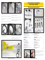
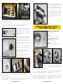
VERSION MOTEUR THERMIQUE
GAS ENGINE VERSION
NOTE : Si vous avez choisi de monter un moteur électrique, passez directement en page 27.
NOTE : If you choose electric power, skip to page 27.
R1
1) Découper l'entoilage sous le fuselage pour dégager les
logements du train.
Cut the covering film under the fuse to open the landing gear
grooves.
2) Utilisez un des cavaliers en nylon pour tracer la position des
trous de fixation.
Use one of the nylon straps to mark the location of fixing
holes.
3) Percez sur ces marques des trous de 2,2 mm.
Drill 2.2 mm holes on theses marks.
4) Fixez le train avec les quatre cavaliers en nylon et huit vis
de 2.8 x 14 mm.
M2
Fit the landing gear and secure it using four nylon straps and
height 2.8 x 14 mm self tapping screws.
V10
V12
V11
V2
V9
M3
F5
V14
5) Placer les roues sur le train.
2) Montez une bague d'arrêt de chaque côté du train et serrez
la vis de pression. Vérifiez que la roue tourne librement.
Fit the wheels on the landing gear.
Install a wheel collar on each side and secure it with the set
screw. Be sure that the wheel can turn freely.
Vous devez maintenant choisir entre une motorisation
électrique ou une motorisation thermique.
You now have to choose : gas power or electric power.
Notice Ecotop - Page 20 - Baron RTF
PIECES POUR MOTORISATION
(M2) Bâti moteur............................................................1 ensemble
(M3) Connecteur de commande....................................................1
(R1) Réservoir et ses accessoires.................................................1
POWER SYSTEM FITTING PARTS
(M2) Engine mount.....................................................................1 set
(M3) Screw lock connector.............................................................1
(R1) Fuel tank and accessories.....................................................1
PIECES FUSELAGE
(F5) Commande de gaz (gaine + tringle)...................................1
PIECES FUSELAGE
(F5) Carburetor linkage (wire and outer tube).....................1
VISSERIE
(V2) Vis CHC M4 x 20...................................................................... 4
(V9) Vis CHC 3 x 25 mm.................................................................. 4
(V10) Ecrou Nylstop M3.................................................................. 4
(V11) Ecrous à griffes M4.............................................................. 4
(V12) Rondelle plate 4 x 8 mm.................................................... 4
(V14) Rondelle plate 3 x 8 mm..................................................... 4
HARDWARE
(V2) M4 x 20 mm socket head screw........................................ 4
(V9) M3 x 25 mm socket head screw......................................... 4
(V10) Lock nut M3............................................................................ 4
(V11) M4 tiger nut............................................................................ 4
(V12) 4 x 8 mm flat washer.......................................................... 4
(V14) 3 x 8 mm flat washer.......................................................... 4
ACCESSOIRES (non fournis)
Servo standard et ses accessoires................................................1
Hélice adaptée au moteur...............................................................1
Ecrou-Cône d'hélice en aluminium (optionnel)......................1
Moteur et accessoires.......................................................................1
Durit silicone..............................................................................60 cm
ACCESSORIES (non included)
Standard size servo and hardware.............................................1
Propeller.................................................................................................1
Aluminium Spinner-nut (optional).............................................1
Engine and accessories.....................................................................1
Silicon fuel tube........................................................................60 cm
1) Mesurez la largeur du carter de votre moteur et les
branches de fixation du bâti, pour déterminer les cotes
de perçage de la cloison pare-feu.
Measure the width of your engine and the arms of the
engine mount, to define the position of the holes on
the firewall.
Notice Ecotop - Page 21 - Baron RTF