1
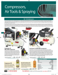
GFN3490
Framing Nailer
Suitable for timber framing, roofing, joists and many other
tasks, this gas powered nailer is a real time saver.
Two batteries are provided, each will last up to 4,000 nails per charge.
There is a built in light to indicate low charge. Standard gascartridges
are used, each with a life of approximately 1,200 nails. This nailer is
powerful but light to use, and able to
drive 51-90mm 34° ring shanked nails
into all timbers with ease.
An adjustable depth control, full
sequential action, effective air filters and a high temperature
warning lamp all contribute to
efficient use. A retractable
rafter hook is a clever idea, saving
an inavertant and possibly terminal
decent! With its Japanese built motor
this is a reliable tool for site or
workshop use.
Axminster Tool Centre,
Unit 10 Weycroft Avenue, Axminster, Devon EX13 5PH
www.axminster.co.uk
Index of Contents...
Page No.
Index of Contents................................................................................................................................................................... 02
Declaration of Conformity................................................................................................................................................... 02
What’s in the Box.................................................................................................................................................................... 03
Symbols...................................................................................................................................................................................... 04
Disposal of Spent NiMh Electrolytic Battery Packs.................................................................................................... 04
General Instructions for Battery Powered Tools and Chargers................................................................. 05-06-07
Safety Instructions for Mains Powered Battery Chargers........................................................................................ 07
General Safety Precautions for Nailers........................................................................................................................... 08
Specifications.......................................................................................................................................................................... 09
Parts Illustration and Description.............................................................................................................................. 10-11
Function Description.......................................................................................................................................................12-14
Operating Instructions..........................................................................................................................................................15
Removing jammed nails................................................................................................................................................ 15-16
Firing Frequency..................................................................................................................................................................... 16
Maintenance................................................................................................................................................... 16-17-18-19-20
After Daily Work...................................................................................................................................................................... 20
Accessories................................................................................................................................................................................20
Troubleshooting......................................................................................................................................................................21
Parts Breakdown......................................................................................................................................................................22
Parts List..................................................................................................................................................................................... 23
Declaration of Conformity...
2.1. The standards and transposed standards EN ISO 121 00-1
:2003, EN ISO 12100-2:2003. EN 792-13:2000+A1 :200B have been
applied correctly.
2.2. The example representing series production of the item
complies with the essential health and safety requirements of the
Directive 2006/42/EC as amended.
2.3. Compliance with EN 60204-1 gives compliance with the
voltage directive 2000J95/EC.
2.4. The file contains all the information to include the following
models in the certification GFN3490, NR90GC. GS683CH. IM90i.
GFN2190. NR90GR, GS683RH-EX. GSR40. IM200. GDA1564.NT65GA.
GT64, NT65GS. IM65. GDT64, NT65GB, IM65A, GT50. GF50. NT50GS,
IMSO F18,GF'N2890 and GCRN45.
Copied from CE Certificate
The undersigned, authorised by
Manufactured by Chongqing Hybest Tools
Group. 57 Jienan Street, Banan District,
Chongqing, China
GFN3490 (Framing Nailer)
1. The technical file contains all the relevant
information.
2. Having verified that the appropriate tests
have been conducted.
Saf
sp irator
Re
Sa
Two
E
y Helm
fet
r
st Mask
Du
fety Viso
Sa
et
Def ende
F ootw
ety
r
ea
n
ar
rs
ro tectio
eP
tiv e Glo
tec
s
ve
n Asse
Ma
Pro
The symbols heigh lighted below advise that you follow
the correct safety procedures when using this machine.
bly
m
d Manu
ea
al
R
SAFETY!!
Ey
!
What’s in the Box...
Model Number:
GFN3490
1 off:
Gas Powered Framing Nailer with Carry Case
A
2 off:
Batteries 7.2V 1.5Ah NiMh
B
1 off:
Battery Charger 230V 50Hz 80W
C
1 off:
Safety Googles
D
1 off
4mm Hex Key
E
1 off:
3mm Hex Key
F
1 off:
Piston Removel Rod
G
1 off
Instruction Manual
Having unpacked your framing nailer, please check the contents against the ‘What’s in the box’ list
above. If there are any pieces missing or damaged, contact our sales and spares department in
accordance with the instructions laid down in our catalogue. Please dispose of any unwanted
packaging responsibly. A lot of the packaging is recyclable.
F
E
G
B
C
A
D
03
Symbols...
You may notice the following symbols used on labels or in the leaflets/manuals associated with your
tools. The meanings of the symbols are shown below:-
40
Recyclable
10
˚C
Temperature
Limitations
Indoors Only
Double
Insulation
Do not dispose in
general rubbish
NiMh Battery
Technology
Disposal of Spent NiMh Electrolytic Battery Packs...
!
Be advised NiMh electrolytic batteries, can constitute a pollution
hazard.
!
DO NOT dispose in clean water run offs
!
DO NOT incinerate
!
DO NOT Dispose of in general household waste.
If you have a spent NiMh Electrolytic battery pack you must dispose of it responsibly.
We respectfully suggest that you contact the local environmental control officer at your local council
and request their procedure for disposing of such waste.
If your local council has no contingencies for dealing with such waste, we are prepared to arrange
disposal on your behalf. What you must do.
Wrap the battery securely in a padded plastic bag to minimise transit damage.
Seal the bag as well as you can (layers of sticky tape?)
Address the bag to: Axminster Power Tool Centre. Axminster, Devon. EX13 5PH.
Please label the bag clearly "NiMh Electrolytic Battery for Disposal"
04
General Instructions for Battery
Powered Tools ...
Good Working Practices/Safety
The following suggestions will enable you to observe good working practices,
keep yourself and fellow workers safe and maintain your tools and equipment
in good working order.
!
WARNING!
KEEP TOOLS AND EQUIPMENT OUT
OF THE REACH OF YOUNG CHILDREN
Good Working Practices/Safety
The following suggestions will enable you to
observe good working practices, keep yourself
and fellow workers safe and maintain your tools
and equipment in good working order.
!
WARNING!! LEAKING BATTERY The
electrolytic in the battery is corrosive,
if a battery is damaged and leaking,avoid contact
with the skin; if contact is made, flush the area
with running water, pat dry and seek medical
attention and advice at the earliest opportunity,
inform the medical service that the contaminant
was a "high alkaline, corrosive liquid". If the
electrolyte comes into contact with the eyes,
flush with copious amounts of water only, seek
medical attention immediately, relaying the
information above.
Battery Powered Tools
Workplace/ Environment
The tools are not designed for sub-aqua
operation, do not use when or where they are
liable to get wet. If tools are set up in the open
and it starts to rain, cover them up or move them
into the dry. If tools do get wet, dry them off as
soon as possible with a cloth or paper towel.
Keep the tools clean, it will enable you to see
more easily any damage that may have occurred.
Clean the tools with a damp soapy cloth if needs
be, do not use any solvents or cleaners as these
may cause damage to the plastic parts or to the
electrical components.
Keep the work area as uncluttered as is
practical, this includes personnel as well as
material. Under no circumstances should
CHILDREN be allowed in work areas.
Do Not carry tools around with fingers near the
trigger switch, and engage the stop-lock of the
tool if one is available. It is preferable to move
small tools e.g. drills and jigsaws to the work
area in their carrying/storage cases; if this is not
possible it is advisable that you do not mount
the blades or drill bits into the tool until you
reach the work area (they make effective
stabbing tools if you trip or stumble).
If you are working from ladders or towers,
ensure they are securely fixed/braced, and
always maintain a balanced, comfortable working
posture; do not over-reach to get the work done,
the extra time required to move the ladder or
tower is a good trade off against injuries
sustained from a fall. Similarly non-slip footwear
and non-slipsurfaces are a good investment.
If the work you are carrying out is liable to
generate flying grit, dust, swarf or chips, wear the
appropriate safety clothing, goggles, gloves,
masks etc; if the work operation appears to be
excessively noisy, wear ear-defenders. If you wear
your hair in a long style, wearing a cap, safety
helmet, hairnet, even a sweatband, will minimise
the possibility of your hair being caught up in
the rotating parts of the tool, likewise,
consideration should be given to the removal
of rings and wristwatches, if these are liable to
be a hazard.
Do not work with tools of any description if
you are tired, your attention is wandering or
you are being subjected to distraction.
A deep cut, a lost finger tip or worse, is not
worth it!
05
Continues Over....
General Instructions for Battery
Powered Tools and Chargers...
DO NOT USE THE TOOLS WITHIN
THE DESIGNATED SAFETY AREAS OF
FLAMMABLE LIQUID STORES OR IN
AREAS WHERE THERE MAY BE VOLATILE
GASES. THERE ARE VERY EXPENSIVE, VERY
SPECIALISED TOOLS FOR WORKING IN THESE
AREAS.
!
Do not discard old batteries or old cutting
tools of any description into general rubbish;
the cutting tools may still be sharp enough to
inflict an injury; batteries if included in
rubbish that is to be disposed of by burning
are an explosion hazard.
Similarly, do not dispose of old battery packs into
clean water run-offs; if they eventually leak, they
will become a pollutant hazard.
When not in use, tools and battery packs should,
ideally, be separated and kept in dry secure
storage, care being taken to ensure that battery
terminals are not liable to be, shorted together
by adjacent metal objects.
Above all, OBSERVE.. make sure you know what
is happening around you, and USE YOUR
COMMON SENSE.
The Tools
Before using the tool read the instructions
thoroughly and make sure you understand them.
Prior to assembling the tool and its battery pack,
carry out a visual inspection of the tool, checking
for damage, or anything untoward. (Do you know
who used it last? That person may be able to
confirm that the tool was "fine" when last used.
Check that the battery terminals are clean and
the casing is not damaged. It is always advisable
to insert nails into the tool with the battery pack
disengaged in case the trigger switch is inadvertently operated; as this is not always practical, use
the stop lock on the tool (if fitted) or keep fingers
away from the trigger switch when handling the
nailer. Check that the nails are seated correctly
Where the workpiece is a small loose item
consider clamping it to a firm work surface to
prevent movement and to enable you to have
both hands free to operate the tool.
Do not drain the battery completely, you will
notice when the performance drops off,
(usually the speed will fall progressively as the
tool is put under load). Change the battery at this
time, not only will you minimise the chance of
damage to the battery but you will prolong its
life expectancy (Number of charges) and also its
ability to accept its full charge capacity.
If the tool becomes excessively hot, perhaps
during or after a long, hard work session allow
the nailer to cool down for at least 10 minutes
Try to avoid work situations that subject the tool
to continuous overheating.
When the work operation is complete, dissemble
the tool, carry out an inspection for damage of
the tool, store in a dry secure area, and re-charge
any depleted battery packs. Do not re-charge
battery packs that have only been subjected to
minimal use, e.g. less than 15 minutes work.
Do not use the charger as a storage facility for
the battery packs, once the charge is complete
remove the battery from the charger and store
separated.
06
Safety Instruction for Mains
Powered Battery Chargers...
1. The charger is for INDOOR use only.
2. Prior to plugging the charger in to the supply,
check that the plug and the cable are in good
condition. If either are damaged, have the
defective item replaced immediately by a
suitably qualified person. If the casing of the
battery charger is damaged, it is good policy to
have the charger checked over by a suitably
qualified person.
3. Only use a correctly rated mains outlet to
provide power, do not plug into site generators,
attach to engine generators or D.C. sources. Do
not use a mains socket outlet that is not
switched.
4. Only use the charger that was supplied with
the battery pack, and vice versa.
5. Do not attempt to charge battery packs that
are too hot (over 40˚C) or too cold (under 10˚C );
if these conditions apply set the battery aside to
"normalise" before proceeding with the charging
operation.
6. Set up the charger and cable in a safe place
where it won’t be knocked, tripped over, stepped
on, etc. and where it is well ventilated; make sure
the ventilation slots in the charger case are not
obstructed, plug the charger into the socket
outlet.
7. Inspect the battery pack for damage; if it is
undamaged, plug it into the charger, ensuring
the correct orientation. (Most chargers and
batteries have ‘keys’ etc, to make sure the
battery is not inserted incorrectly, if you are
having to force the battery into the charger, the
chances are you have it the wrong way round,
check and try again.)
8. Switch the charger on and check that the
correct indicators illuminate, allow the battery
pack to charge (see the specific instructions for
your charger). Once charging is complete, switch
the charger off, remove the battery pack and
store, repeat the procedure if you have more
than one battery to charge. Note that some
RAPID chargers require a rest period between
charges, read the instruction manual concerning
your specific charger to see if this is the case.
After charging is complete, unplug the charger
from the socket outlet by pulling on the plug.
(Do not pull on the cable). Store the charger in a
dry secure place.
9. If, when the charger was switched on, the
correct indications did not occur, leave for two or
three minutes to allow the charger to stabilise; if
the correct indications occur, allow the charging
cycle to proceed as normal. If no indication
appears at all, switch off, remove the battery
pack, unplug the charger, check that the charger
contacts and the battery contacts are clean and
repeat the process; if there is still no indication,
switch off, remove the battery pack, unplug the
charger and check the fuse. If the fuse is blown,
replace and repeat the process; if the fuse blows
again, or if the fuse was intact, attempt no further
action. Refer the charger to a suitably qualified
person for assessment/repair.
07
General Safety Precautions for Nailers...
1. KEEP WORK AREA CLEAN. Cluttered areas
invite injuries.
2. KEEP CHILDREN AWAY. All children should be
kept away from the work area. Don't let them
handle the tool.
11. STAY ALERT. Watch what you are doing. Use
common sense, do not operate any tool if you
are tired or subject to distraction, a nailer fired
into any part of your anatomy can cause serious
injury.
3.PRESCRIPTION MEDICATION. Read the
warning labels on all medicines to determine if
your judgment or reflexes would be impaired. If
there is any doubt, do not attempt to operate
this tool.
12. STORE IDLE EQUIPMENT. When not in use,
remove the fuel cell and battery cartridge, the
tool should be cleaned, unloaded, lightly oiled,
stowed away in its carrycase, and stored away
in a dry location to prevent the possibility of
rusting. The storage position should be out
of reach of children
4. USE EYE PROTECTION. Eye protection should
conform to BSI specifications and provide
protection against flying debris from the front
and the side. Eye protection should be worn
when loading, unloading, servicing or operating
this tool.
13. CHECK. Walls, cellings, floors and roofing
carefully to avoid possible electrical shocks,
gas leakage, etc. caused by stricking live wires,
conduits or gas pipes.
5. USE EAR DEFENDERS. Repetitive high noise
levels can damage hearing. If the work area in
which you are operating has excessively high
noise levels, wear ear protection.
6. WEAR APPROPRIATE CLOTHING. Protective
gloves and non-skid footwear/safety shoes are
recommended when operating this tool. Don't
wear loose clothing or jewellery. They can get
caught in moving parts. If you wear your hair in
a long style, a safety helmet, hat, protective hair
covering or even a sweatband will help to
minimise the chance of hair being caught up in
the tool.
8. DO NOT OVERREACH. Keep proper footing
and balance at all times, do not over reach,
especially when working from ladders or towers,
the extra time required to reposition the tower or
ladder is a good trade off against a potentially
crippling fall.
9. CHECK THE TOOL FOR DAMAGE. Before using
the tool, check for damage, any part that
seems damaged should be carefully checked to
determine that it operates properly and will
perform its intended function. If there is any
doubt, have the tool repaired and tested by a
suitably qualified person.
10. REPLACEMENT PARTS AND ACCESSORIES.
When servicing, only use approved replacement
parts. Only fit the approved accessories intended
for use with this tool.
14. DO NOT allow uninstructed persons to use
the tool.
15. BE AWARE OF OTHER PEOPLE. Make sure
no one is near by be fore using the nailer. Nails
may rip through or fly off, causing serious injury.
ON ROOFTOPS and other high locations, nail as
you move forward, it’s very easy to loose your
footing if you are nailing while moving
backwards.
A NAIL can become bent or the tool can become
jammed if you mistakenly nail on top of another
nail or if you strike a knot in the wood. The nail
can be thrown causing injury to someone close
by.
ALWAYS. Use nails recommended in our
catalogue or no our web site.
!
WARNING: The warnings, cautions
and instructions discussed in this
instruction manual cannot cover all possible
conditions and situations that may occur. It
must be understood by the orematic that
COMMON SENSE AND CAUTION ARE
FACTORS WHICH CANNOT BE BUILT INTO
THIS TOOL. THEY MUST BE APPLIED BY THE
OPERATOR.
08
Specification...
Axminster No.
953497
Rating:
Trade
Battery No/Capacity:
2 x 3000mAh
Battery Voltage/Type:
2 x D. C. 7.2V NiMh
Battery Life:
4000 Nails per Charge
Cycle Rate:
2-3 Nails per second
Nail Angle:
34˚
Nail Head/Collation Type:
Clipped/Paper
Nail Length x Shank Diameter:
L: 50 - 90mm D: 2.87-3.33mm
Fuel Cell LIfe:
1200 Nails
Charge Time:
3 hours
Load Capacity:
68 Nails
Overall L x W x H:
378 x 374 x 110mm
Weight:
3.75kg
Battery Charger Model:
HYCH0503601500G
Power Supply:
230V AC 50Hz 80W
Charging Current:
7.2-24 D.C. 1.5A
Charging Time:
3 hours
09
Parts Illustration and Description...
The tool is fully assembly when you receive it.
The information below is a description of the
Filter Cover
framing nailer and to get a better understanding
of the functions.
Fuel cell cover
Battery
Motor housing
Exhaust shield
Magazine
Trigger
Indication lamp
Magazine lock
Contact element
Fig A
Fig B
10
Parts Illustration and Description...
Charger
NiMh Battery
RED LED GREEN LED
FLASHING
Battery
Terminal
Charger
Terminal
T
-
+
+
s
Green LED indication lamp charger is ‘ON’
Red LED indication lamp ‘FLASHING’ , battery is being charged
Red and Green indication lamp ‘ON’ battery is charged
11
Function Description...
Charging the battery
The batteries are shipped discharged and must
be charged prior to first use. Locate the charger
(C) and one of the two 7.2V batteries (B). Plug
the charger into the mains and switch on. The
GREEN LED indicator will light up. Insert the
battery (B) into the charger, NOTE MAKE SURE
THE BATTERY IS IN THE CORRECT
ORIENTATION IN THE CHARGER. (See figs 1
and 2) The RED LED will start flashing and charging will commence. Charging time will take
approximately three hours. When charging is
complete both LED indicators will stay on.
Disconnect the
battery charger (C) from the mains and remove
the battery (B) from the charger.
NOTE: Over usage such as over-charge,
over-discharge and high temperatures will
result in a short life span. To avoid this the
batteries should be charged and discharged
once every three months.
Fig 1
Fig 2
RED LED
FLASHING
B
C
GREEN LED
Installing or removing the battery
Fuel cell
Attaching the metering valve to the fuel cell
Hold the battery (B) so the lock button is on top.
Inset the battery into the installment opening to
the rear of the nailer (A), see fig 3 and insert it in
until it clicks home.
! WARNING DO NOT USE FORCE when
inserting the battery cartridge. If it does not slide
in easily, it is not being inserted correctly.
To remove the battery (B), press down the lock
button and pull the battery back.
1) Metering valve
2) Cap
1
2
Remove the cap (2), push in the metering valve
front edge (1) then push in the back edge until it
seats. (See fig 4)
Fig 4
Front
edge
Back
edge
Fig 3
A
1
B
12
Function Description...
Installing the fuel cell
Fig 5
Fig 6
a
1) Push in fuel cell lock and open the cover.
2) Insert the fuel cell into the compartment.
Direct the jet nozzle valve (a) towards the
adapter (b). (See figs 6 and 7)
Fig 7
Fig 8
a
b
3) Insert the jet nozzle (a) into the small hole
in the adapter (b). Make sure it is inserted
properly.
4) Close the fuel cell cover.
Adjusting the nail depth
Fig 10
CAUTION: Before adjusting nail depth,
remove the fuel cell, the battery and
the nail magazine before continuing.
!
Using a 4mm Hex key loosen the two Hex screws
as shown in fig 9 and move the contact element.
Re-tighten the Hex screws and replace the spring
(See figs 10-11)
Fig 9
Fig 11
Spring
13
Function Description...
Indication lamp
Loading the nails
The colour of the indication lamp functions is as
follows:
!
CAUTION: Before loading the nails
remove the fuel cell and battery
before continuing.
• Blue lamp on:
1) Depress the magazine lock button and pull it
back to the rear of the magazine until it lock in
place.
Normal status
• Red/Blue lamps flashing alternately:
2) Insert the nail strip into the magazine.
Indication that the unit is overheating. Remove
the battery (B), and leave the unit to cool down
for 5 minutes then replace the battery (B) and
continue with operation.
3) Depress the lock button in and gently lower
the magazine lock until it’s up against the nail
strip. Release the button to lock the assembly in
place (See figs 14-15-16)
• Red lamp on: battery low
Fig 14
Remove the battery and recharge.
Hook
The hook is convenient for hanging the tool
temporarily when not in use.
Pull out the steel hook (a) from the moulded
recess in the nailer casing and hook it over a
solid structure (See figs 12-13).
Fig 12
Fig 15
a
Fig 16
Fig 13
14
Operating Instructions...
Operation
!
Removing jammed nails
CAUTION: Before operating the
nailer check that the nail strip and
fuel cell has been inserted correctly
Step 1: Insert the battery pack into the nailer as
described earlier in the manual. Position the
contact element against the workpiece. The fan
motor will start, fuel is injected into the
combustion chamber which is mixed with the
air by the fan.
Step 2: While holding the nailer in position,
squeeze the trigger, the spark plug will ignite the
fuel/air mixture driving the piston down onto the
nail which interns fires it into workpiece. (See fig
17)
!
CAUTION: Remove the fuel cell and
the battery before continuing.
To remove the jammed nails follow the
instructions below.
1. Remove the two Hex screws (a) and place
assembly (b) safely aside.
2. Remove the contact element (c).
3. Push up the drive plate (d) remove the
two Hex screws (e) and threaded retaining
block (f) place safely aside.
4. Open the fuel cell cover and pull
handle/magazine away from nose and clear
the jam. (See figs 19-20-21-22-23)
Fig 19
a
Fig 17
Contact
element
b
Fig 20
Step 3: Lift the nailer away form the workpiece
then release the trigger which opens the
combustion chamber to allow the fan to blow
the hot gases through the exhaust vents.
c
Anti dry fire mechanism Lock
This mechanism prevents the tool from firing
when the nails have depleted. (See fig 18)
Fig 18
d
Fig 21
Anti-dry fire mechanism lock
When you have finished remove the battery, fuel
cell and the nail strip
e
15
Continues Over....
Operating Instructions...
Maintenance...
Fig 22
!
CAUTION: Always remove the
battery, fuel cell and nails before
carrying out any maintenance
2
f
Remove the threaded retaining block (f)
1
Fig 23
3
Cleaning the air filter
After 12,000 cycles the following service
procedures should be carried out
Fig 25
5. After you have removed the jammed nail
reassemble the nailer but in reverse.
(NOTE: make sure you line up the steel latch
with the raised plastic moulding, see fig 24
below, otherwise the assembly will not merge
correctly).
Fig 24
Plastic moulding
1. Open the air filter cover
Fig 26
Steel latch
Firing Frequency
• Non-continuous operation: 2 to 3 nails
per second
2. Clean the air filter using compressed
air or soap and water
• Continuous operation: 1200 nails per hour
• No more than 5000 nails per day
16
Maintenance...
Cleaning the cylinder head
Fig 30
1. Remove the four Hex bolts (a) using a 4mm
Hex key and place safely aside.
2. Remove the cylinder head cover and place
safely aside.
3. Remove the two Hex screws (b) from the fuel
cell compartment.
c
4. Remove the spark plug lead (c).
Fig 31
5. Lift out the cylinder head assembly.
(See figs 27-28-29-30-31)
a
Fig 27
6. Remove the steel O-ring (d) and clean the fan,
cylinder head assembly with de-greaser and
wipe with a dry cloth. Replace the O-ring.
(See figs 32-33)
Fig 32
Fig 28
d
Fig 29
Fig 33
b
17
Continues Over....
Maintenance...
7. Clean the spark plug electrode with a small
brush. (See fig 34)
3. Locate the piston removal rod (G), screw the
threaded end into centre of the piston (b) and
remove the piston assembly. (See figs 37-38)
Fig 34
Fig 37
G
8. Press down the piston and clean the
combustion chamber with de-greaser and
wipe with a dry cloth. (See fig 35)
Fig 38
9. Replace the cylinder head assembly as
described on the previous page but in reverse.
Fig 35
b
4. Clean the combustion chamber with
de-greaser and wipe with a dry cloth.
5. Clean the piston with de-greaser and check for
signs of wear and tear at the end of the firing
pin.
Cleaning the piston chamber
After 50,000 cycles the following service
procedures should be carried out
1. Remove the cylinder head as described on the
previous page.
2. Press down the piston, remove the circlip (a)
with a pare of pliers and clean with de-greaser.
(See fig 36)
Fig 36
Note: The firing pin should have a flat edge.
If there is signs of burring to the edges or
small cracks emerging, the piston assembly
will need to be replaces. Contact our Technical
Sales department on 0330 100 0299 for a
replacement.
6. After cleaning the piston (b), re-insert the
assembly into the combustion chamber, replace
the circlip and reassemble the cylinder head as
described on the previous page.
a
Cleaning the exhaust vents
After 100,000 cycles the following service
procedures should be carried out
If you find the nails are not being fired into the
workpiece properly the exhaust vents may need
cleaning.
18
Maintenance...
1. Remove the two Phillips screws (a) on top of
the front cover (b), place safely aside.
beneath the exhaust plate, see fig 43, place these
spacers safely aside.
Fig 42
2. Following the instructions illustrated on top of
the cover, remove the cover (b) and place aside.
(See figs 39-40)
Note: The cover my be tight to remove, a little
force may be needed.
Note: Beneath the cover there are two plastic
washers resting on the top exhaust plate (c),
remove them and place safely aside. (See fig 41)
Fig 43
Fig 39
b
a
Fig 40
5. Remove exhaust plate valve (d), clean with
de-greaser and place safely aside. (See fig 44)
6. Blow out the exhaust vents with a air line and
clean the manifold. (See fig 45)
Fig 44
d
Fig 41
c
Exhaust vents and manifold
Fig 45
3. Using a 4mm hex key remove the four hex
screws and place them safely aside. (See fig 42)
4. Lift away the exhaust plate (c), Note be careful
when removing, there are two depth spacers
19
Continues Over....
Maintenance...
7. Replace the exhaust assembly as described on
the previous page but in reverse order.
Fig 46
After Daily Work..
Before leaving work site
1. Remove the battery (B) and place it in the tool
carryng case.
2. Dispose of all empty fuel cells properly by
taking them to a recycling centre.
Twin pack gas fuel cells
Order no: 210705
Fig 47
CAUTION: There may be gas fumes still in the
fuel cells. Keep them away from children and
DO NOT crush, puncture and above all DO
NOT throw them onto a fire.
When you get home
1. Place the battery (B) in the Changer (C) if it
needs changing.
2. Wipe the nailer over with a clean, soft cloth.
3. Check the air filter and clean if dustly.
Box kits of 2,200 nails with two gas fuel cells
or 3,300 nails with 3 gas fuel cells
Fig 48
To maintain product safety and reliability, if
there are any other repairs or adjustments
to be made it should be carried out by a
qualified technician. Contact Axminster Tool
Centre on 0800 371822
Accessories...
The GFN3490 gas nailer uses the same nails
and fuel cells as many other brands, see our
catalogue or visit our website at
www.axminster.co.uk for details.
Nailer cleaning kit
Order no: 210704
20
Troubleshooting...
21
Parts Breakdown...
22
Parts List...
23