1
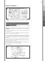
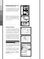
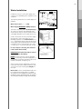
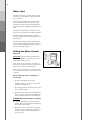
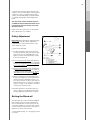
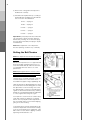
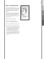
Breezair EA Series
Installation Manual
Table of Contents
ITEM
PAGE
ITEM
General Safety Rules
Employers and Employees Responsibilities
1
Other Important Requirements
2
Precautions
2
Unpacking the EA
2
Cooler Location and Orientation
2
Mounting the Cooler
3
Electrical Installation
4
Weatherdamper and Latch
5
Bleed-off Fitting
5
Water Installation
6
Water Level
7
Setting the Motor Current
Pulley Adjustment
Setting the Bleed-off
Setting the Belt Tension
7, 8
8
8, 9
9
Setting the Motor Low Speed
10
Installation Checklist
11
Testing the Cooler
11
Evaporative Air Cooling Manual. Seeley International Pty Ltd, Adelaide, South Australia. A.C.N. 054 687 035.
As the policy of the company is one of continuous product improvement, all specifications are subject to change without
notice.
1
Employers and Employees Responsibilities
The installation and maintenance of evaporative air coolers at high levels has the
potential to create Occupational Health and Safety issues for those involved.
Installers are advised to ensure they are familiar with the relevant State and National
legislations, such as Acts of law, Regulations, approved Codes of Practice and
Standards. Compliance with these regulations will require appropriate work practices,
equipment, training and qualifications of workers.
Seeley International provides the following information as a guide to contractors
and employees to assist in minimising risk whilst working at high levels.
INSTALLER AND MAINTENANCE CONTRACTORS
A risk assessment is an essential element that should be conducted before the
commencement of work, to identify and eliminate the risk of falls or to minimise
these risks by implementing control measures.
RISK ASSESSMENT
A risk assessment of all hazardous tasks is required by law. This should be
considered in terms of:
•
What are the chances of an incident happening?
•
What could the possible consequence be?
•
What can you do to reduce, or completely eliminate the risk?
SOME POINTS TO CONSIDER
•
What is the best and safest access to the roof and working areas?
•
If a worker is alone, who knows they are there and if they get into difficulty, how
can they summon help? (Call someone on the ground? Mobile phone? etc.)
•
What condition is the roof in? Should the trusses, underside or surface be
checked?
•
Does the worker have appropriate foot wear? (Flat sole jogger type is advisable)
•
Are all power cables/extensions leads safe and appropriately rated?
•
Are all ladders, tools and equipment suitable in good condition?
•
Where ladders are to be used, is there a firm, stable base for them to stand
on? Can they be tied or secured in some way at the top?
•
Is there a roof anchor to attach a harness and landyard to? If so, instruction
should be issued for the use of an approved harness or only suitably trained
people used.
•
Are all tools and materials being used, prevented from slipping and falling onto
a person at ground level? Is the area below the work area suitably protected
to prevent persons walking in this area?
•
Does the work schedule take into account weather conditions, allowing for
work to be suspended in high winds, thunder storms/lightning or other types
of weather giving wet, slippery surfaces?
•
Is there an on-going safety check system of harnesses, ropes, ladders and
access/lifting equipment and where they exist on roofs, anchor points before
the commencement of work?
•
Is there a system which prevents employees from working on roofs if they are
unwell or under the influence of drugs or alcohol?
2
•
Are there any special conditions to consider i.e. excessive roof pitch, limited
ground area, fragile roof/walls, electrical power lines or a temporary power
source?
Other Important Requirements
For lifting or pulling the cooler into position using ropes or slings, always apply the
ropes around the blower housing. Never tie them to any or all of the four round
corner posts.
Never force parts to fit because all parts are designed to fit together easily without
undue force.
Never drill any holes in the primary base surface or side walls of the bottom tanks
(reservoir) of the cooler nor in the side walls of the tank.
Check the proposed cooler location, to ensure that it is structurally capable of
supporting the weight of the cooler, or provide an adequate alternate load bearing
structure.
Air coolers installed at high levels on walls must have an adequate, safe platforms
for maintenance personnel.
Precautions
Lifting and installing the Air Cooler is made easier by removing the cooling pad
frames first. They can be replaced at the end of the installation procedure.
You can slide the Air Cooler from one place to another if you wish but lifting and
carrying is better. It is recommended that at least two (2) people carry the Air Cooler
whenever it needs to be moved.
Do not drop the Air Cooler. Always handle with care.
Unpacking the Cooler
Remove the external straps, cardboard and plastic
bag. Remove a pad frame (Fig.2) to locate the
accessories inside the cooler.
Dispose of all the packaging wisely and in
accordance with local regulations.
Cooler Location and
Orientation
Check the proposed cooler location, to ensure
that it is structurally capable of supporting the
weight of the cooler, or provide an adequate
alternate load bearing structure.
Always locate the cooler where it will receive a
plentiful supply of fresh air. Not in a recess where
it may be starved for air or where the air is polluted.
Ensure the location is a minimum of : 3 metres
from a solid fuel heater flue, 1.5 metres from
a gas flue, 5 metres from a sewer vent and
600mm from a wall.
3
Carefully consider neighbouring residences and
noise levels when locating the cooler, if necessary
talk to the customer and the neighbour before
carrying out the installation.
Mounting the Cooler
DOWN DISCHARGE (See Fig. 3, 4, 5 & 6)
Place the cooler as shown. Make sure the blower
is facing in the correct direction to enable
unobstructed air flow into the duct (Fig. 3).
Check that the weatherdamper moves without
obstruction.
Fix the cooler to the vertical duct with the eight
(8) self tapping screws provided (2 screws per
side). If the vertical duct is firmly secured to the
roof, any additional support frame for the cooler
is not required.
Screw length must be limited to a maximum of
1.5” (40mm) to avoid interfering with the
weatherdamper. After securing the cooler, check
for free operation of the weatherdamper over its full
travel (see ‘Weatherdamper and Latch’ section
- page 5).
Always be sure that the air cooler is level after
fitting on to the duct.
SIDE DISCHARGE
A mounting frame is required to be supplied by
the installer.
Always allow adequate space to remove cooling
pads for cleaning.
Always provide safety hand rails where necessary.
Connect the cooler to the duct flexible connection
on the side of the cooler.
Always be sure that the air cooler is level after
fitting on to the duct.
TOP DISCHARGE
A mounting frame is required to be supplied by
the installer.
Always allow adequate space to remove cooling
pads for cleaning.
Always provide safety hand rails where necessary.
Always be sure that the air cooler is level after
fitting on to the duct.
4
Electrical Installation
Installation of the air cooler must conform to local electrical rules, regulations and
standards.
It is a requirement of Seeley International that all coolers be wired with a
dedicated circuit to the distribution board. Each air cooler must have a
separate fuse or circuit breaker.
WARNING! Check to be sure that the voltage rating of the air cooler is compatible
with your electrical system voltage.
The Electrical Installation must be carried out by a licensed and qualified
electrician.
Sub-circuit wiring should be rated at 10 amps minimum or greater, depending on
the rating plate data.
The wall control is located in a convenient place inside the house or building to
allow easy control of the air cooler functions.
Prior to completion of the installation the electrician must check that the Air Cooler
is operating correctly and must set the motor full load amps. Use a long type (or
clip-on) ammeter to make the adjustments at the adjustable motor pulley. See later
instructions.
Electrical circuit wiring and its covering is to be continuous all the way into the
junction box inside the cooler. The point of the entry into the cabinet of the air
cooler is shown in Figs. 14, 15 & 16.
Ensure that all electrical connections are tight. Loose connections cause
overheating which can result in machine malfunction.
Replace all covers.
5
Weatherdamper and Latch
(Down Discharge Coolers only)
The weatherdamper latch performs two functions
(Fig. 9). In the locked position it acts as a transport
latch preventing movement during transport. In
the operating position it acts as a restrainer
preventing gusts of wind from opening it.
After the cooler is installed, squeeze the latch
and rotate it clockwise to its operating position.
Lift the latch and check by lifting the counter
weight, that the weatherdamper flap is free to
move. The counterweight should move freely
through 90° (Fig. 10).
Bleed-off Fitting
A special plastic ‘bleed-off’ fitting is supplied with
every air cooler. This has three functions. It acts
as an overflow, a drain and a bleed-off. The bleedoff fitting comprises a small tray which collects
water from under one of the cooling pads and
drains this small quantity of water to waste.
A large hole (50mm diameter) is pre-drilled in the
base of the water reservoir (tank). The bleed off
fitting should be installed at this position (Fig. 11).
Make sure that it is correctly located in relation
to cooling pad frame and that the large ‘O’ ring
is on before placing it into the hole. The nut must
be screwed up firmly by hand from underneath.
It is a requirement of Seeley International Never drain the water directly on to the roof.
Use a separate hose or pipe.
Do not lose the ‘O’ ring supplied with this kit.
Use of the bleed-off fitting is mandatory in order
to protect the air cooler from excessive salt buildup
and component failure.
A special bleed stop cap is available for use in
areas that prohibit bleed-off (Fig. 12 for fitting
instructions). In this case all plugs in the bleed
funnel must be removed as per diagram.
This cooler may be supplied with an AUTO
DRAIN KIT. If so, these instructions about bleed
(above) remain in force.
6
Water Installation
Installation of the air cooler water supply must
conform to local plumbing rules, regulations and
standards.
The following specifications for water supply are
required:
Water Connections : Z\x " BSP
Water Supply MAXIMUM : 800Kpa (115psl)
The water connection point for down discharge
air coolers is located on the underside of the
water reservoir (tank) at the point where the float
valve nipple protrudes from the bottom (Fig. 14).
Install a manual shut off valve in the water supply
line adjacent to the Cooler subject to local
plumbing regulations. It is recommended to use
a Z\v turn ball type shut off valve. This allows the
water supply to be isolated whenever work needs
to be done on the Cooler. DO NOT use a stop
cock (faucet), i.e. a non-return type shut off valve.
In areas subject to freezing, the water line
needs a drain down facility.
IMPORTANT! Flush the water pipe to remove
any swarf before final fitting.
NOTE! The float valve has a plastic threaded
nipple for connecting to the water supply line. Do
not overvalve, it is plastic. Use teflon tape on the
threads and tighten carefully (Fig. 14).
Always ensure that the supple pipe connection
to the float valve does not place sideways strain
onto the float valve. Run the pipe straight into
the valve.
Drain water from the overflow/bleed outlet must
be carried away through a pipe to a suitable
discharge point on the building or property (usually
the drain or gutter). The pipe may be any material
which will withstand direct sunlight and weathering.
16
7
Water Level
Rotate the large float clockwise until it reaches
the limit of its travel without coming off the arm
(Fig. 14 page 6).
Turn off the water supply and allow the water
reservoir to fill with water. The float valve will
eventually stop the water from entering the Air
Cooler. Wait for this to happen and observe water
level.
Rotate the float around anti-clockwise a small
amount to let more water in and observe the level.
Continue the procedure until the water level
remains at about 15mm below the top lip of the
bleed-off tray.
The water level should never be adjusted with
the Air Cooler and pump running because the
water in the filter pads will run back into the water
reservoir and might overflow.
Setting the Motor Current
(Amperes)
Important! The motor pulley and belt tension
need to be adjusted to ensure that the motor is
running at its rated capacity.
If the current is set too low, the cooler will not
perform to its optimum capacity, and the motor
speed control may not work effectively.
If the current is too high, the motor will overheat.
It is most important that the motor current is set
correctly.
Before setting the motor current please
ensure that:
• All ducts and registers are in place.
• Windows and doors in rooms to be cooled
are open sufficiently, and
• All cooling pad frames except the one on the
motor side are in place.
(1) Run the motor at maximum speed by operating
the cooler from the wall control, in "MANUAL"
mode, maximum fan speed, ventilation only.
WARNING! Ensure that the pump is not running.
(2) Continue running the motor for 10 minutes
(warms up the motor) before proceeding with
the current measurement.
(3) Measure the motor current with a long type
ammeter. Attach the ammeter around one of
the motor cables inside the terminal box as
shown (Fig. 17).
17
8
Compare the measured current with the rated
current on the motor nameplate. If the measured
current is less than, or greater than the rated
current, the adjustable pulley should be altered
accordingly. See heading "Pulley Adjustment"
below.
The measured current should be equal to,
or within 0.5 amperes below that of the motor
rated current. It must never be more than
the rated current.
Replace all covers and switch off clamp meter
when adjustments are complete.
Pulley Adjustment
Important! Never attempt this adjustment with
the air cooler operating. Pulley adjustment is
made with the cooler power turned off at the
switch inside the cooler.
(1) Remove the drive belt.
(2) To adjust the pulley: Remove the securing
screw that holds the locking cap in place, then
remove the cap. The adjustable half of the
pulley is now free to be adjusted by rotating
it on it's thread (Fig. 18).
(3) To increase the blower speed and therefore
increase the amps, the two halves of the pulley
must be closer together, i.e. turn the adjustable
half clockwise (pulley in).
(4) To decrease the blower speed and therefore
decrease the motor amps, the two halves of
the pulley must be further apart, i.e. turn the
adjustable half anti-clockwise (pulley out).
(5) When an adjustment is made: Replace the
locking cap, aligning the screw hole with the
nearest hole in the adjustable sheave. Lock
it into place with the securing screw. Refit the
belt, ensuring tension is correct, (i.e. no slipping
and not too tight, as this will effect the motor
current) then check the amps.
(6) Smaller adjustments should be made each
time you approach the desired setting. See
heading ‘Setting the Belt Tension' (Page 9).
Setting the Bleed-off
All Evaporative Air Coolers should be equipped
with a bleed-off function which will reduce the
level of salt build up in the water reservoir. The
continuous bleeding of a small amount of water
to drain ensures that fresh water is allowed in, to
dilute the salt in the water reservoir.
To set the bleed-off (Figs. 11 & 12 page 5) proceed
as follows:
18
9
(1) Remove the cooling pad frame adjacent to
the bleed-off assembly.
(2) The bleed rate required will vary according to
water quality, but should be set to the minimum
rate as set out in the table below:
EA 70.......0 plugs in.
EA 90.......0 plugs in.
EA 120.......1 plug in.
EA 145.......1 plug in.
EA 150.......1 plug in.
Important! In poor quality water areas where the
salt and mineral contents are high, adjust the
bleed rate by inserting one or more extra plugs
than specified in the table (more plugs in equals
more bleed off).
Note! Bleed adjustment cannot be precise,
because operating conditions vary continually.
Setting the Belt Tension
19
Note! This adjustment must be done immediately
after the motor current adjustment has been
completed.
Belt tension is important, if it is too tight there will
be excessive belt and bearing wear. If it is too
loose there will be belt slip and excessive wear,
accompanied with noise and loss of cooler
performance.
Note! Adjusting belt tension is not the correct
way to alter motor current. The current can only
be altered by adjusting the motor pulley.
The belt tension should be adjusted so that the
maximum deflection is 15mm-20mm when a
reasonable force (approx 1.5kg) is applied (Fig. 20).
There are two bolts for adjusting belt tension. These
are located on the motor mounting plate. To make
the adjustment, loosen the locking nuts on the
two adjusting bolts on the motor mounting plate.
Tighten or slacken the belt tension by screwing
the bolts in or out respectively. When the adjustment
is correct, tighten the locking nuts again.
It is important to check the motor current rating
again after making any alterations to the belt
tension. This may require a further adjustment to
the motor pulley, which may have been slipping,
giving an incorrect reading.
Correct belt tension ensures the belt will not slip.
Check the temperature of the belt after running
for 30 seconds following each adjustment. If the
belt is warm to touch, then it is slipping. Continue
tightening until the belt runs cool.
20
10
Motor Low Speed Setting
EA variable speed coolers will function across a
wide speed range. The minimum speed has been
factory set, and should not require adjustment
under normal circumstances. However, some
adjustment may be necessary to suit each
installation.
After you have set the motor current and belt
tension correctly, check the speed variation of the
cooler. When the control is changed from
maximum to minimum settings, there should be
an easily recognizable difference in fan speed,
not motor current.
If there is not, check the following:
(1) That windows and doors are open.
(2) That the weatherdamper transport latch is
undone and in the operating position.
(3) That the weatherdamper is able to move freely.
If the above are all correct then proceed as follows:
(4) Turn the minimum speed adjustment knob (Fig.
21) clockwise or anti-clockwise, until the belt
is running at approximately one revolution per
second (this equates to a fan speed of
approximately 600 rpm). Switch the fan off
then on again, to ensure that it spins fast
enough to open the weatherdamper and keep
it open. It is important to allow the cooler to
run for a while on minimum speed, to ensure
the weatherdamper remains in the fully open
position.
21
11
Installation Check List
Check the following on initial start up:
1.
Is the air cooler level?
2.
Is the drain/overflow pipe installed?
3.
Are all the roof or wall penetrations properly sealed? (i.e. ducts, electricity
wiring, main supply water pipe, drain pipe, drain/overflow pipe)
4.
Are there any water leaks in the water supply system?
5.
Is the water level correct?
6.
Is the electrical wiring properly grounded (earthed) at both ends?
7.
Check that the Aspen pads are correctly in place, and there are no air gaps
at the top of the pads due to movement in transportation.
8.
Check that the galvanised wire pad securing frames are correctly positioned
into all holes and clips.
9.
Is the motor tightly mounted and secure?
10. Is the V-belt adjusted as specified?
11. Is the motor pulley tight on the shaft?
12. Is the motor pulley properly aligned with the fan pulley?
13. Is the pump running OK? Check by turning it on by itself. Does it wet all the
filter pads?
14. Is the fan running in the correct direction? Should be clockwise when viewed
from the pulley.
15. Does the fan operate at all speeds?
16. Was the fan motor current checked?
17. Has the owner been instructed in correct operation of the system and
supplied with the owners manual?
Testing the Cooler
Once you are satisfied that the Cooler is installed and commissioned correctly, it
is important to run the cooler and ensure that everything is working as it should.
Check that the cooler runs quietly and with a balanced distribution of air to all
outlets.
Make sure there are no water leaks. Check the drain fittings and pipes, making
sure there are no leaks.
Clean up the Site
Clean up and tidy the premises, removing all rubbish.
Information extracted from Booklet 838373-E.