1
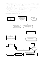
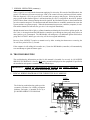
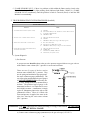
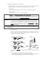
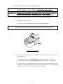
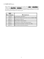
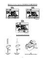
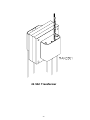
Hot Surface Ignition (HSI) System Booklet American Dryer Corporation 88 Currant Road Fall River MA 02720-4781 Telephone: (508) 678-9000 / Fax: (508) 678-9447 E-mail: [email protected] 010298MFM/abe ADC Part No. 450178 Retain This Manual In A Safe Place For Future Reference American Dryer Corporation products embody advanced concepts in engineering, design, and safety. If this product is properly maintained, it will provide many years of safe, efficient, and trouble-free operation. ONLY properly licensed technicians should service this equipment. OBSERVE ALL SAFETY PRECAUTIONS displayed on the equipment or specified in the installation/ operator's manual included with the dryer. THE HSI MODULE IS NOT FIELD REPAIRABLE and THE HSI GAS VALVE IS NOT FIELD REPAIRABLE We have tried to make this manual as complete as possible and hope you will find it useful. ADC reserves the right to make changes from time to time, without notice or obligation, in prices, specifications, colors, and material, and to change or discontinue models. WARNING: UNDER NO CIRCUMSTANCES should the door switch or the heat circuit devices ever be disabled. WARNING: The dryer must never be operated with any of the back guards, outer tops, or service panels removed. PERSONAL INJURY or FIRE COULD RESULT. NOTE: The wiring diagram for the dryer is located on the right wall, inside the Left Coin Panel area. Replacement parts can be obtained from your distributor or the ADC factory. When ordering replacement parts from the factory, you can FAX your order to ADC at (508) 678-9447 or telephone your orders directly to the ADC Parts Department at (508) 678-9000. Please specify the dryer model number and serial number in addition to the description and part number, so that your order is processed accurately and promptly. The illustrations on the following pages may not depict your particular dryer exactly. The illustrations are a composite of the various dryer models. Be sure to check the descriptions of the parts thoroughly before ordering. IMPORTANT NOTE TO PURCHASER Information must be obtained from your local gas supplier on the instructions to be followed if the user smells gas. These instructions must be posted in a prominent location near the dryer. GAS HOT SURFACE IGNITION (HSI) SYSTEM MODEL TRITON 2465 (Part No. 128974) 50/60 Hz TYPE ONLY PRODUCT INFORMATION and TROUBLESHOOTING GUIDE NOTE: Failure to read and follow ALL instructions and information included in this manual carefully before operating and/or servicing this system, COULD CAUSE PERSONAL INJURY and/or PROPERTY DAMAGE. IMPORTANT: We have tried to make this manual as complete as possible and hope you will find it useful. However, since the time of this printing, some information contained herein may have been updated. ADC RESERVES THE RIGHT TO MAKE CHANGES FROM TIME TO TIME, WITHOUT NOTICE or OBLIGATION IN PRICES, SPECIFICATIONS, COLORS, and MATERIALS, and TO CHANGE or DISCONTINUE MODELS or PARTS. Table of Contents A. INTRODUCTION ............................................................................... B. GENERAL SYSTEM INFORMATION ........................................... HSI (Hot Surface Ignition) System Components/Functions ........ D. 3 thru 6 3 Failure To Light - LOCKOUT ..................................... ................ 3 and 4 Flame Failure Reignition ............................................................. 4 and 5 System (basic) Electrical Ratings/Specifications ......................... C. 2 6 HSI (Hot Surface Ignition) SYSTEM OPERATION ........................ 6 thru 9 HSI System Operation .................................................................. 6 thru 8 HSI System Operation (Flow Chart) ............................................ 8 Normal Operation (summary) ....................................................... 9 TROUBLESHOOTING ...................................................................... 9 thru 17 Test Equipment .............................................................................. 11 HSI Troubleshooting Terms (definitions) ............................. 11 and 12 Troubleshooting/System Diagnosis (detailed) ...................... 12 thru 17 D. PARTS LIST (basic) ........................................................................... 18 thru 20 1 A. INTRODUCTION 1. The Hot Surface Ignition (HSI) System operates at 24 VAC and is a discrete component based gas ignition control (HSI module) system which utilizes a Hot Surface Ignitor as an ignition source. Safe proof of flame is accomplished through flame rectification. The HSI module has a diagnostic LED (light emitting diode) indicating light which simplifies troubleshooting in the event of a fault. Other Features · 24 VAC microprocessor based HSI control · System diagnostic L.E.D. (light emitting diode) · Automatic reset one (1) hour after lockout · Multiple tries · Custom pre-purge and interpurge timing · Remote and local sensing · Flame sense test pins · Software conforms to UL 1998 requirements · Design certified to ANSI Z21.20 and CAN/CSA C22.2 No. 199-M89 2 B. GENERAL SYSTEM INFORMATION 1. HOT SURFACE IGNITION (HSI) SYSTEM COMPONENTS/FUNCTIONS: a. The HSI MODULE is designed to be the controller of the HSI system. When activated by the dryers controls, this module constantly monitors and controls the functions of the HSI system (i.e., ignitor activation, gas valve on and off functions, flame verification, etc.), can be operated at either 50 Hz or 60 Hz; and has self diagnostic capabilities. The red L.E.D. (indicator light) on the HSI module simplifies the troubleshooting procedure in the event of a fault within the HSI system. If the LED on the HSI module does not blink constantly, then the system is functioning properly. A blinking red L.E.D. (LOCKOUT MODE) indicates that ignition flame has not been confirmed. Refer to the TROUBLESHOOTING SECTION of this manual for specific diagnostic information. The green indicator L.E.D. on type 2 and 3 is a helpful troubleshooting clue to let the user know the Hot Surface Module has received the thermostat or sail switch voltage (24 VAC). 1) Failure To Light - LOCKOUT a) Should the main burner fail to light, or if a flame is not detected during the first trial for ignition period, the gas valve is de-energized and the HSI module goes through an interpurge delay before another ignition attempt. The control will attempt two (2) additional ignition trials before going into LOCKOUT and the gas valve will be de-energized immediately. 1) Recovery from LOCKOUT requires a manual reset by either resetting the thermostat or sail switch or removing the 24 VAC from the HSI module for a period of five (5) seconds. 2) Hot Surface Module There are three types of H.S.I. modules. The system operations of the three are exactly the same. What differs between the modules are some positions of terminations and a green L.E.D. indicator has been added. This green indicator L.E.D. is an enhanced feature to let the user know the 24 VAC thermostat voltage has reached the hot surface ignition module. TYPE 1 TYPE 2 3 TYPE 3 (2) If the microprocessor (computer) is still calling for heat after one (1) hour, the HSI module will automatically reset and attempt to ignite the burner again. 2) Flame Failure Re-ignition a) If the established flame signal is lost while the burner is operating, the HSI module will respond within 0.8 seconds. The gas valve is de-energized, the HSI module resets and starts a new ignition sequence in an attempt to relight the burner. If the burner does not light, the HSI module will de-energize the gas valve. The HSI module will make two (2) more attempts to relight the burner. If the burner does not relight, the HSI module will go into LOCKOUT. If flame is reestablished, normal operation resumes. IMPORTANT: The HSI MODULE is a precision instrument, and should be handled carefully. ROUGH HANDLING or DISTORTING COMPONENTS COULD CAUSE THE MODULE TO MALFUNCTION. WARNING: THE HSI MODULE IS NOT FIELD REPAIRABLE. NOTE: To reset the HSI MODULE if it is in the LOCKOUT MODE, open and close the main door then restart the dryer. If the module repeatedly goes into LOCKOUT, refer to the TROUBLESHOOTING SECTION of this manual. b) The 24 VAC TRANSFORMER is designed to step down the operating (primary) voltage of the dryer from 120 VAC, 208 VAC, or 240 VAC to the 24 VAC (secondary voltage) which is necessary to operate the HSI system and in some cases the controls of the dryer. The 24 VAC TRANSFORMER has multi-primary taps which allow for one (1) transformer to be used for any voltage application including 120 volt, 208 volt, or 240 volt. Refer to the SERVICE INFORMATION SECTION of this manual for specific transformer and wiring termination information. 24 VAC Transformer c. The HOT SURFACE IGNITOR/FLAME SENSOR ASSEMBLY is located in the burner flame area and is used to ignite the gas by the use of a HOT SURFACE IGNITOR. To provide feedback information to the HSI module a FLAME SENSOR is used to determine whether the burner flame is evident (on). 4 The HOT SURFACE IGNITOR is a silicon carbide ignitor that upon application of 24 VAC will glow bright orange for the interpurge time period. The proper location of the silicon carbide ignitor is very important to achieve optimum system performance for both ignition and flame sensing. After the interpurge period the gas valve will open. Upon ignition, the resistance in the flame sensor electrode changes and the information is sent to the HSI module via the sensor probe lead connection to the module. Once the resistance is changed and sensed, the HSI module will sustain the gas flow (provide 24 VAC power to the gas valve). Hot Surface Ignitor Flame Sensor Assembly d. The HSI 24 VAC GAS VALVES used are of the redundant type which means the gas valve is actually two gas valves in one; one in series with the other. This is a safety feature which provides protection against gas flow in the event of a failure of one of the valves to seat properly. Other features are that the gas valves have a manual shut off, a pressure tap outlet, and are designed for easy conversion to regulated L.P. gas. 36E Redundant Gas Valve WARNING: THE HSI GAS VALVES ARE NOT FIELD REPAIRABLE. IMPORTANT: THERE ARE NO PARTS AVAILABLE FOR FIELD REPAIR. Replace the gas valve only with exact model or type number as noted on gas valve. 5 2. SYSTEM (basic) ELECTRICAL RATINGS/SPECIFICATIONS INPUT POWER CONTROL: 18-30 VAC 50/60 Hz INPUT CURRENT DRAIN 300 mA @ 24 VAC with GAS VALVE RELAY ENERGIZED (control only) GAS VALVE RATING 2.0A @ 24 VAC OPERATING TEMPERATURE 0° F (Fahrenheit) to 160° F (Fahreheit) 0° C (Celsius) to 71° C (Celsius) FLAME SENSITIVITY .7µA minimum FLAME FAILURE RESPONSE TIME 0.8 seconds maximum TYPE of GASES NATURAL, L.P. (liquid propane), or manufactured SIZE (length x width x height) 4.23 x 3.23 x 1.63 (with cover) 10.75 cm x 8.21 cm x 3.97 cm (with cover) WEIGHT 5 ounces (nominal) 145 grams (nominal) ENCLOSURE GRAY (Noryl N-190) FIRE RETARDANT PLASTIC TRIES FOR IGNITION three (3) TRIAL FOR IGNITION PERIOD 4 seconds INTER-PURGE 3.5 seconds C. HSI (Hot Surface Ignition) SYSTEM OPERATION 1. HSI SYSTEM OPERATION a. The HSI Modules red indicator light will light for up to approximately five (5) seconds (self check routine). If the HSI Modules red indicator light stays on or flashes continuously, then the HSI module is wired incorrectly or has failed. b. Start the drying cycle. If all the safety devices, (sail switch, 225º F or 330º F thermostats are closed. The green L.E.D. indicator light will come on and stay on. This indicator will stay on through out the heating cycle, until the voltage (24 vac) is stopped to the H.S.I. module via thermostats, computer. c. The Hot Surface Ignitor will turn on. After approximately four (4) seconds the Hot Surface Ignitor will shut off and the gas valve will be energized. The flame should now be established. 6 TYPE 1 d. With the burner flame on, remove the flame sensor wire from the S2 terminal of the HSI module. The burner flame must shut off immediately. e. Stop the drying cycle, with the flame sensor removed, restart the drying cycle. TYPE 2 TYPE 3 7 f. The Hot Surface Ignitor will turn on and after approximately four (4) seconds the Hot Surface Ignitor will shut off. The gas valve will be energized and a burner flame should be evident for approximately seven (7) seconds and then shut off. g. The HSI Module will attempt two (2) additional ignition trials after which the HSI Module will LOCKOUT and the red indicator light will flash 3 blinks, wait one (1) second, and then keep flashing 3 blinks continuously until the HSI Module is reset manually. h. Functional check of the HSI (Hot Surface Ignition) Module is complete. 2. HSI SYSTEM OPERATION (Flow Chart) Green L.E.D. indicator comes on, (only types 2 and 3) HSI Module Enters Internal Routine Check L.E.D. Indicator Stays On Approx. 4 Seconds Hot Surface Ignitor Starts To Glow Computer Calls For Heat If L.E.D. Continuously Blinks Twice in Succession There Is a Fault In The Heat Sensing Circuit If L.E.D. Indicator Stays On Continuously Replace HSI Module Open and Close Main Door Restart Dryer Approx. 4 Seconds Later Gas Valve Opens HSI Module LOCKOUT -------------------------------Module L.E.D. Will Continuously Blink 3 Times In Succession Approx. 4 Seconds Later Hot Surface Ignitor Shuts Off Ignition Evident? (FLAME VERIFIED) -------------------YES NO HSI Module Will Wait 15-17 Seconds And Then Go Into Retry Mode HSI Module Will Attempt To Retry Twice Normal Heating Cycle Flame Not Established After Retrys HSI Module Will Wait 15-17 Seconds And Then Go Into Retry Mode Flame Out FLAME NOT VERIFIED HSI Module Will Attempt To Retry 3 Times 8 3. NORMAL OPERATION (summary) When a signal is received from the thermostat supplying 24 volts to the W terminal of the HSI module, the green L.E.D. indicator will come on (only type 2 and 3), the control will reset, perform a self check routine, flash the diagnostic L.E.D. for up to four (4) seconds and a pre-purge delay begins. Following the interpurge period, the Hot Surface Ignitor is activated and the gas valve is energized for the trial for ignition period. When a flame is detected during the trial for ignition, the Hot Surface Ignitor is deactivated and the gas valve remains energized. The thermostat and main burner flame are constantly monitored to assure the system continues to operate properly. When the thermostat microprocessor controller (computer) is satisfied and the demand for heat ends, the gas valve is de-energized immediately. Should the main burner fail to light, or a flame is not detected during the first trial for ignition period, the Gas Valve is de-energized and the HSI Module (controller) goes through an inter-purge delay before an other ignition cycle is attempted. The HSI Module will attempt two (2) additional ignition trials before going into LOCKOUT and the gas valve relay will be de-energized immediately. Recovery from LOCKOUT requires a manual reset by either resetting the thermostat or removing the 24 volts for a period of five (5) seconds. If the computer is still calling for heat after one (1) hour the HSI Module (controller) will automatically reset and attempt to ignite the burner again. D. TROUBLESHOOTING The troubleshooting information provided in this manual is intended for use only by QUALIFIED SERVICE TECHNICIANS. Observe ALL safety precautions displayed on the equipment or specified in the installation and operators manual included with the dryer. IMPORTANT: UNDER NO CIRCUMSTANCES SHOULD ANY SAFETY OR HEAT CIRCUIT DEVICE EVER BE DISABLED. 1. TYPICAL WIRING DIAGRAM OF THE THREE TYPE H.S.I. MODULE TYPE 1 The following troubleshooting guide provides systematic procedures for isolating equipment problems, and again, is intended for use by a QUALIFIED SERVICE TECHNICIAN. 9 TYPE 2 TYPE 3 10 TEST EQUIPMENT The following pieces of test equipment will be required to troubleshoot this system with minimal time and effort. MANOMETER Used to measure gas pressure in inches of water column (W.C.) Available from ADC - Part No. 122804 MULTIMETER/VOLTMETER For measuring voltage and/or amperage 1. HSI (Hot Surface Ignition) TROUBLESHOOTING TERMS (definitions) a. INTERNAL CONTROL FAILURE - HSI module red L.E.D. (light emitting diode) indicator light stays on continuously. This indicates there is a system fault and most likely the fault is the HSI Module itself. b. HSI MODULE RED L.E.D INDICATOR LIGHT - this light is located on the top left side of the HSI Module (refer to the illustration on pages 3 or 6 of this manual). This DIAGNOSTIC INDICATOR simplifies the operational and troubleshooting procedures of the system. c. FLAMEOUT - burner flame shut down by the HSI Module due to lack of flame verification. This condition occurs only after ignition has been evident but is lost. The HSI system will immediately attempt to relight the burner for a total of three (3) times before going into LOCKOUT. Once in the LOCKOUT MODE the HSI Module must be reset manually d. TRIAL FOR IGNITION (T.F.I.) - the period after the Hot Surface Ignitor shuts off and before the gas ignites. e. LOCKOUT - when the flame is lost or the gas is not ignited after three (3) tries. The red L.E.D. (light emitting diode) indicator light flashes 3 blinks (i.e., LOCKOUT) continuously until the HSI Module is reset manually. 11 f. FLAME SENSOR FAULT - if there is a problem or fault within the flame sensing circuit or the Flame Probe, the red L.E.D. (light emitting diode) indicator light flashes 2 blinks (i.e., FLAME SENSOR FAULT) continuously until the problem or fault is corrected (fixed) or until the HSI Module is reset manually. 2. TROUBLESHOOTING/SYSTEM DIAGNOSIS (detailed) TROUBLESHOOTING (Service Checks) Cause SYMPTOM 1. NO L.E.D. INDICATOR LIGHT (GREEN OR RED) A. B. C. D. MISWIRED TRANSFORMER BAD (24 volts), THERMOSTAT, FUSE/CIRCUIT BREAKER BAD HSI MODULE BAD 2. GAS VALVE ON - NO HOT SURFACE IGNITOR A. B. C. DEFECTIVE HOT SURFACE IGNITOR MISWIRED HSI MODULE BAD (check v oltage at Hot Surf ace Ignitor) 3. HOT SURFACE IGNITOR ON - NO GAS VALVE A. B. C. GAS VALVE COIL OPEN OPEN GAS VALVE WIRE (MV1 or GN D) HSI MODULE BAD (check for volt age bet ween MV1 and GN D) 4. FLAME OKAY FOR T.F.I. (TRIAL FOR IGNITION) NO FLAME AFTER T.F.I. A. B. C. D. DEFECTIVE HOT SURFACE IGNITOR S2 WIRE BAD POOR GROUND (GND) AT BURNER POOR FLAME (check flame current) OR SAIL SWITCH FAULTY a. System Diagnosis 1) Gas Pressure A gas pressure test should be taken at the gas valve pressure tap provided on every gas valve to assure that the water column (W.C.) pressure is correct and consistent. There are two (2) types of devices used to measure water column (W.C.) pressure. They are the spring and mechanical type gauge and the water column test gauge (manometer). The use of the spring and mechanical type of gauges is NOT RECOMMENDED because they are very easily damaged and they are not always accurate. The preferred type of gauge is the manometer because it is a simple devise to use and is highly accurate. A manometer is simply a glass or transparent plastic tube with a scale graduated in inches. When it is filled with water and pressure is applied, the water in the tube rises, showing the exact water column (W.C.) pressure. WARNING: Test ALL connections for leaks by brushing on a soapy water solution. NEVER TEST FOR LEAKS WITH A FLAME! a) Connect water column test gauge (manometer) to the gas valve tap (1/8 N.P.T.). 12 b) Start the dryer with the burner on, the correct water column (W.C.) reading in inches should be: Natural Gas ........................................ 3.5 - 4 inches W.C. L.P. (liquid propane) Gas .................. 10.5 - 11 inches W.C. When a gas dryer is first started (during initial time of installation or start-up), it has a tendency not to ignite on the first ignition attempt. This is due to the fact that the gas supply piping is filled with air, so it may take a few minutes for the air to be purged from the supply lines. During this purge period, there may be insufficient gas pressure for ignition, which might cause the HSI module to go into the LOCKOUT MODE (the L.E.D. will LIGHT RED CONTINUOUSLY). NOTE: During the purge period, check to be sure that ALL gas shut-off valves are open. NOTE: To reset the HSI MODULE if it is in the LOCKOUT MODE, open and close the main door then restart the dryer. 2) Flame Sensor a) Flame Sensor Fault Code The HSI Module is equipped with a diagnostic circuit that detects a fault in the Flame Sensor Probe or any related circuits in the internal circuits in the HSI module. When a fault is detected, the red L.E.D. (light emitting diode) indicator light will flash 2 blinks. To clear this code either discontinue power to the dryer and HSI Module or replace the FLAME PROBE or HSI MODULE. FLAME SENSOR CURRENT CHECK (Same Test Points on all three tyes) b) Flame Sensor Current Check Flame current is the current which passes through the flame from the Flame Sensor to ground (GND). The minimum flame current necessary to keep the HSI system from LOCKOUT is .7 microamps. To measure flame current, connect an analog D.C. (direct current) micrometer to the FC1 and FC2 terminals (refer to the adjoining illustration). The meter should read .7 microamps or higher. If the meter reads below 0 on the scale, then the meter leads are reversed. Disconnect power and reconnect the meter leads for proper polarity. 13 c) Flame Failure Re-ignition If the established flame signal is lost while the burner is operating, the HSI module (controller) will respond within 0.8 seconds. The gas valve will be de-energized, the HSI module resets and starts a new ignition sequence in an attempt to relight the burner. If the burner does not light, the HSI module will de-energize the gas valve. The HSI module will make two (2) more attempts to relight the burner. If the burner does not relight the HSI module will go into the LOCKOUT MODE. If the flame is reestablished, normal operation resumes. d) Fault Conditions FAULT CONDITION INDICATIONS ERROR MODE L.E.D. I NDICATION INTERNAL HSI MODULE FAILURE STEADY ON FLAME SENSOR FAULT 2 FLASHES IGNITION LOCKOUT 3 FLASHES The red L.E.D. (light emitting diode) will flash on for a 1/4 second, then off for a 1/4 second during a fault condition. The pause between the fault codes is three (3) seconds. NOTE: To reset the HSI MODULE if it is in the LOCKOUT MODE or the FLAME SENSOR FAULT MODE, open and close the main door then restart the dryer. 3) HSI (Hot Surface Ignition) Module The HSI module (controller) utilizes a microprocessor to continually and safely monitor, analyze, and control the proper operation of the gas burner. Additional features consist of L.E.D. diagnostics, automatic one (1) hour reset, multiple tries, and flame current testing pins highlight the HSI module benefits. The terminal designation that are listed below correspond to the designations on the bottom portionof the HSI module (as shown from left to right). TYPE 1 TERMINAL DESIGNATIONS FC1/FC2 ........ S1 ................... L1 ................... L2 ................... S2 ................... W .................... MV1 ............... GND ............... FLAME SENSOR CURRENT CHECK POINTS IGNITOR 24 VOLT INPUT (HOT) CONSTANT NOT USED (N EUTRAL - 120V INPUT ONLY) IGNITOR REMOTE SENSOR/FLAME SENSOR THERMOSTAT INPUT MAIN VALVE POWER System Ground 14 TYPE 2 TYPE 3 15 4) HSI (Hot Surface Ignition) 24 VAC Transformer The HSI transformer is designed to step down the operating voltage of the dryer to 24 VAC to operate the HSI module. This transformer, like all transformers, is two (2) sided: a) Primary Side This is the incoming voltage side - 120 VAC, 208 VAC, 240 VAC - of transformer. b) Secondary Side This is the step down side - 24 VAC - of the transformer. WARNING: 208 VAC and 230/240 VAC ARE NOT THE SAME. ALL voltage connections should be checked and confirmed according to the wiring diagram provided with the individual dryer. Any damage done to dryer components due to improper voltage connections will automatically VOID THE WARRANTY. IMPORTANT: The ADC Service Department must be contacted prior to any wiring change or conversion because, depending on the change/conversion required, some parts may have to be added, deleted, or changed. When contacting the ADC Service Department they must be given the correct model number and serial number of the dryer(s). NOTE: Any wiring changes or conversions should be by a QUALIFIED ELECTRICAL TECHNICIAN. (1) Transformer Wiring There are six (6) color-coded wires coming from the 24 VAC Transformer. There are four (4) wires coming from the primary (incoming) voltage side of the transformer. Their application and color-coding are as follows: (a) For 120 VAC application ONLY; 1 - The BLACK and WHITE wires are used. 2 - The Red and Blue wires are capped off individually. (b) For 208 VAC application ONLY; 1 - The BLACK and BLUE wires are used. 2 - The Red and White wires are capped off individually. (c) For 240 VAC application ONLY; 1 - The BLACK and RED wires are used. 2 - The White and Blue wires are capped off individually. There are two (2) ORANGE wires coming from the secondary (step down) side of the transformer; (d) One (1) ORANGE wire is connected to the GND (ground) termination. (e) One (1) ORANGE wire supplies the 24 VAC signal for the control and/or HSI system circuit. (Refer to the specific wiring diagram with the dryer for connection point.) 16 4) HSI (Hot Surface Ignition) 24 VAC Redundant Gas Valve IMPORTANT: The HSI 24 VAC Redundant Gas Valve contain no serviceable parts. REPLACEMENT COILS ARE NOT AVAILABLE. IMPORTANT: THERE ARE NO PARTS AVAILABLE FOR FIELD REPAIR. Replace gas valve only with exact model or type number as noted on gas valve. a) The redundant gas valve utilize 24 VAC, which is provided by the HSI module. (1) To check the resistance value; (a) Disconnect the terminations at the gas valve from the HSI module. WARNING: When taking ohm readings, the terminations from the HSI module must be disconnected or removed, otherwise, the readings obtained will be incorrect. 36E Redundant Gas Valve (2) With a meter (either a multimeter or ohmmeter) set on the 200 ohm position, place the meter leads across: (a) Terminals 1 and 2, the reading should be approximately 96 ohms +/- 5 ohms. (b) Terminals 2 and 3, the reading should be approximately 96 ohms +/- 5 ohms also. (3) If, after checking the resistance values on the gas valve, it is determined that the ohm readings do not approximate the ohm values listed above (96 ohms [+/- 5 ohms] for both readings respectively), then, the gas valve must be replaced. 17 E. PARTS LIST (basic) When ordering replacement parts from the factory, please specify model and serial numbers in addition to the part number and description of the dryer so that your order can be processed accurately and promptly. The information and illustrations listed here may not depict your particular dryer part exactly. This information and/or illustrations are a composite of the HSI SYSTEM. Be sure to check the part description thoroughly before ordering any part. ADC PART N UMBER DESCRIPTION 128918 128927 881479 881495 881597 881500 881797 FLAME SENSOR ASSEMBLY HSI 24 VAC R EDUNDANT GAS VALVE (36E01-204) HOT SURFACE IGNITOR HSI 24 VAC TRANSFORMER HOT SURFACE IGNITOR (MILNOR DRYERS) H.S.I. MODULE (MODELS AD-530, WDA-530) H.S.I. MODULE (MILNOR DRYERS) 18 HSI (Hot Surface Ignition) SYSTEM COMPONENTS TYPE 1 TYPE 2 TYPE 3 Hot Surface Ignition (HSI) Module Hot Surface Ignitor 36E 24 VAC Redundant Gas Valve Flame Sensor Assembly 19 24 VAC Transformer 20 ADC 450178 1- 01/02/98-46 4* 05/21/98-50 7- 02/01/00-10 2- 01/05/98-20 5* 07/16/98-50 8- 02/25/00-75 3- 02/25/98-50 6* 03/31/99-50