1
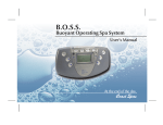
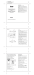
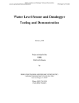
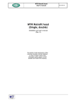
Oper
ation/
Opera
Installa
tion
Installation
Manual
SP600 SERIES
W ATER METER
Model Number:
___________
Serial Number:
___________
Date of Installation: ___________
Baxter • 19220 State Route 162 East • Orting, WA 98360 •
Phone: (360) 893-5554 • Toll free: 1-800-280-2495 • Fax: (360) 893-6128
FORM 36702 Rev. A (Jan. 2005)
TABLE OF CONTENTS
GENERAL ........................................................................................................................................... 3
INSTALLATION ................................................................................................................................... 3
Unpacking ................................................................................................................................. 3
Location ................................................................................................................................... 3
Wall Mounting ........................................................................................................................... 3
Installation Codes and Standards ............................................................................................4
Electrical Connections ............................................................................................................. 4
Water Supply .............................................................................................................................6
Drain Connections ....................................................................................................................6
Plumbing Connections ............................................................................................................. 7
Assembly ...................................................................................................................................9
Setting Water Pressure ............................................................................................................9
OPERATION .......................................................................................................................................10
Environmental Conditions .......................................................................................................10
Controls ...................................................................................................................................10
Before First Use ......................................................................................................................12
Using the SP600 Water Meter ................................................................................................13
Using the Temperature Probe ................................................................................................14
Flush Time ...............................................................................................................................15
Shutdown .................................................................................................................................15
Cleaning ...................................................................................................................................15
MAINTENANCE ..................................................................................................................................16
Service and Parts Information ................................................................................................16
Calibration Check ....................................................................................................................16
TROUBLESHOOTING .......................................................................................................................20
–2–
INSTALLATION, OPERATION AND CARE OF
BAXTER MODEL SP600 WATER METER
SAVE THESE INSTRUCTIONS
GENERAL
The SP600 Water Meter is a microcomputer-controlled water delivery system that enables you to
accurately control the water requirements for your baking needs. Through the proper control of water
temperature and volume, the SP600 will help you gain uniform baking results and maximum productivity.
Baxter Water Meters are produced with quality workmanship and material. Proper installation, usage
and maintenance of your water meter will result in many years of satisfactory performance.
It is suggested that you thoroughly read this entire manual and carefully follow all of the instructions
provided.
INSTALLATION
The water meter requires separate hot and cold supply lines. Each line should have a manual shutoff
valve (not supplied) at the water meter for servicing and shutdown. Before installing, verify that the
electrical service agrees with the specifications on the data plate located on the left panel of the water
meter. If the supply and equipment requirements do not agree, do not proceed with the installation.
Contact the Bakery Systems service department immediately.
UNPACKING
This water meter was inspected before leaving the factory. The transportation company assumes full
responsibility for safe delivery upon acceptance of the shipment. Immediately after unpacking, check
for possible shipping damage. If the water meter is found to be damaged, save the packaging material
and contact the carrier within 15 days of delivery.
LOCATION
Before finalizing location, make sure that consideration has been given for water supply, draining,
electrical outlets and service clearances.
WALL MOUNTING
The water meter has a detachable base for wall mounting. It is secured by a machine screw located
on the bottom panel.
1. With the water meter lying flat, control face up, remove the machine screw and angle holddown.
2. Slide the water meter forward and set aside.
3. Position the base on the wall and level left-to-right using a carpenter’s level.
–3–
4. Mark the position and hole location.
5. Mount the base to the wall using the appropriate mounting fasteners.
6. Slide the water meter, with the control panel facing up, downward onto the base. Make sure the
horizontal groove on the back of the water meter is lined up with the top edge of the base.
7. Secure water meter to the base with the machine screw and angle holddown.
8. Check to make sure the water meter is level.
INSTALLATION CODES AND STANDARDS
The water meter must be installed in accordance with:
In the United States of America:
1. State and local codes.
2. National Electrical Code, ANSI/NFPA-70 (latest edition). Copies may be obtained from The
National Fire Protection Association, Batterymarch Park, Quincy, MA 02269.
In Canada:
1. Local codes.
2. Canadian Electric Code, CSA C22.1 (latest edition). Copies may be obtained from The Canadian
Standard Association, 178 Rexdale Blvd., Etobicoke, Ontario, Canada M9W 1R3. (electric
equipment)
In Europe:
1. Local codes.
ELECTRICAL CONNECTIONS
WARNING: ELECTRICAL AND GROUNDING CONNECTIONS MUST COMPLY WITH THE
APPLICABLE PORTIONS OF THE NATIONAL ELECTRICAL CODE AND/OR OTHER LOCAL
ELECTRICAL CODES.
WARNING: APPLIANCES EQUIPPED WITH A FLEXIBLE ELECTRIC SUPPLY CORD ARE
PROVIDED WITH A THREE-PRONG GROUNDING PLUG. THIS PLUG MUST BE CONNECTED
INTO A PROPERLY GROUNDED THREE-PRONG RECEPTACLE. IF THE RECEPTACLE IS NOT
THE PROPER GROUNDING TYPE, CONTACT AN ELECTRICIAN. DO NOT REMOVE THE
GROUNDING PRONG FROM THIS PLUG.
Electrical data is located on the left panel as you face the water meter. Route the power cord safely out
of the way of other equipment, personnel and moisture.
If the equipment is used in a manner not specified by the manufacturer, the protection provided by the
equipment may be impaired.
–4–
Units with 120VAC Power Supply
•
Replace any UL listed fast-acting 1A/250VAC
fuse inside the water meter if fuse is blown.
Units with 230VAC/250VAC Power Supply
•
For 230VAC/250VAC operation, replace any
UL listed fast-acting 3A/600V fuse inside the
junction box if fuse is blown.
Input power line and branch circuit protection will be
provided and wired by customer. Refer to Fig. 1 for
240V junction box wiring diagram.
NOTE: It is recommended that a switch or circuit
breaker (marked as the connecting device) is located
near the equipment and within easy reach of the
operator.
Fig. 1
Water Chiller Option
If water chiller is pump-driven, connect the chiller to the water meter as described in the steps below.
Connection to the water chiller circuit should be done by a qualified electrician or service technician.
The auxiliary switch is located in the top-mounted junction box.
WARNING: DISCONNECT THE ELECTRICAL POWER TO THE MACHINE AND FOLLOW
LOCKOUT / TAGOUT PROCEDURES.
1. Verify that the water chiller circuit does not exceed the auxiliary relay rating.
2. Remove the junction box cover screws, cover and gasket.
3. Connect water chiller and meter per Fig. 2.
4. Install the junction box gasket and cover.
Secure with the previously removed junction
box screws.
5. Connect power to the meter. While test is
flowing, verify that the water chiller pump motor
is running in the proper direction.
Fig. 2
–5–
WATER SUPPLY
The water meter requires separate hot and cold supply lines. A manual shutoff valve (not supplied)
should be installed on each supply line at the water meter to accommodate servicing and shutdown.
•
HOT WATER INLET TEMPERATURE: 140°F (60°C) recommended.
•
HOT AND COLD WATER FLOWING PRESSURE: 30 psi (207 kPa) minimum.
•
WATER HARDNESS: 4 to 6 grains per gallon (0.7 to 1.0 grains per liter) is recommended.
DRAIN CONNECTIONS (FIG. 3)
The water meter should be located near a sink for the bypass line to drain into while test flowing or when
water is adjusting to a set temperature.
For water meters equipped with a water chiller and with a water reservoir, a bypass return line should
be connected back to the water chiller reservoir.
WATER METER AND HAND SINK SETUP
NOTE: The hot and cold water supply lines can vary in location.
Fig. 3
–6–
PLUMBING CONNECTIONS
WARNING: PLUMBING CONNECTIONS MUST COMPLY WITH APPLICABLE SANITARY,
SAFETY AND PLUMBING CODES.
Connection to the water supply should be done by a qualified plumber or service technician.
Make sure the water lines are thoroughly flushed out before connecting to the water meter. This
flushout is necessary to remove all foreign matter, such as chips (resulting from cutting or threading
of pipes), pipe joint compound from the lines or, if soldered fittings are used, bits of solder or cuttings
from the tubing. Debris, if not removed, may lodge in the valves and render them inoperative.
Manual valves or solenoid valves damaged by foreign matter, and any expenses resulting from this
damage, may not be covered under warranty.
Water Chiller Option
1. Connect the water meter cold water supply tubing to the water chiller pump outlet tubing (Fig. 4).
2. Connect the bypass line (supplied) from the water chiller tank to the test flow bypass port on the
bottom of the water meter (Fig. 4). Use the bypass line hose fittings (supplied).
3. If not provided, drill a 1 1/32" (26.2 mm) hole through the lid of the water chiller tank, and install the
bypass line hose fitting and nut (supplied).
WATER METER WITH OPTIONAL WATER CHILLER AND PLUMBING CONNECTIONS
NOTE: The Hot and Cold Water Supply lines can vary in location.
Fig. 4
–7–
/COMPONENTS
WATER METER WITH PLUMBING CONNECTIONS
NOTE: The Hot and Cold Water Supply lines can vary in location.
Fig. 5
–8–
ASSEMBLY
The water meter is supplied with external fittings/components that must be assembled before the water
supply is connected.
•
Assemble the fittings to the water meter as shown in Fig. 5. Use teflon tape or pipe joint compound
when assembling.
•
The union connection on the water meter has a flat doughnut gasket. Make sure the gasket is
in place before connecting any fittings.
•
Plug the hand held temperature probe into the end of the flexible cable attached to the bottom
panel of the meter.
SETTING WATER PRESSURE
For the water meter to operate properly, the water pressure should be set at 30 psi (207 kPa) on each
regulator while it is operating at 125°F (52°C). See Operation on the following pages for a description
of the control panel.
1. Press CHANGE UNITS to select English or Metric units. (If the CHANGE UNITS key is locked,
see Locking and Unlocking the Change Units.)
2. Press SET TEMP and enter 125°F (52°C) on the numeric key pad. The water temperature value
is displayed in the WATER TEMPERATURE window.
3. Hook the dispensing hose over the rim of a sink or drain.
4. Press SET AMOUNT and enter 20 lbs 00 oz.
5. Press START. The water begins dispensing from the bypass line. The actual water temperature
of the flowing water is displayed in the WATER TEMPERATURE window.
6. Allow the flowing water temperature to reach 125°F (52°C) and switch over to delivery.
7. Adjust both hot and cold water regulators until the pressure gauges read 30 psi (207 kPa).
–9–
OPERATION
ENVIRONMENTAL CONDITIONS
•
Indoor use at altitudes up to 6,500 ft. (2,000 m).
•
Main supply voltage fluctuations up to +/-10% of nominal voltage.
•
Installation category III, pollution degree II.
•
The normal ambient operating temperature is between 41°F (5°C) and 105°F (40°C). The normal
operating water temperature is between 32°F (0°C) and 125°F (52°C).
CONTROLS
Hand Held Temperature Probe
The temperature window displays the temperature recorded by the hand held probe. The probe
measures the temperature of the room, dough or flour. The temperature range is 32°F to 125°F (0°C
to 52°C).
Water Temperature
SETTING window - Displays the water temperature as the water meter is dispensing. It also displays
the selected water temperature when the meter is idle.
FULL COLD light - Indicates the mixing valve is using cold water only.
ADJUSTING light - Indicates the mixing valve is adjusting the water temperature.
FULL HOT light - Indicates the mixing valve is using hot water only.
– 10 –
Water Amount
SETTING window - Displays the amount of water to be delivered, in pounds and ounces. Up to five
digits may be entered; the last two digits are always for ounces.
Setting ranges are as follows:
Pounds: 0 to 999
Ounces: 0 to 15
Liters: 0 to 461
Centiliters: 0 to 99
DELIVERED window - Displays the amount of water dispensed in pounds and ounces.
BY-PASS light - Indicates the meter is dispensing out of the bypass line.
DELIVERING light - Indicates the meter is dispensing the entered water amount out of the dispenser
hose.
INTERRUPTED light - Indicates the meter has stopped before all of the water amount could be
delivered.
COMPLETED/READY light - Indicates the meter has dispensed the entered water amount, and is
ready for the next dispensing cycle.
– 11 –
Control Panel
For complete control of the water meter functions, a numeric key pad and the following control keys are
provided.
CHANGE UNITS key - Press to change °F to °C and pounds to liters. If CHANGE UNITS key is locked,
see Locking and Unlocking the Change Units on page 14.
SET TEMP key - Press to enter desired water temperature. Enter the value on the numeric key pad.
SET AMOUNT key - Press to enter the amount of water you would like to dispense. Enter the value
on the numeric key pad.
START/RESUME key - Press to dispense the entered water amount. Press to resume dispensing
cycle after an interruption.
STOP/0 key - Press to stop dispensing water.
BEFORE FIRST USE
The water meter should be checked for dispensing accuracy before operation begins. See Calibration
Check on page 16.
– 12 –
USING THE SP600 WATER METER
Change Units (English/Metric)
When the Water Meter is first powered up, press CHANGE UNITS to select the English units
(Fahrenheit and Pounds) or Metric unit (Celsius and Liters). If the unit of measure DO NOT change,
the CHANGE UNITS key is locked. See Locking and Unlocking the Change Units on page 14 to unlock.
1. Press CHANGE UNITS to select Fahreheit or Celsius.
2. Press CHANGE UNITS to select Pounds/Ounces or Liters/Centiliters.
The Units can be changed individually as follows:
Change Temperature Unit:
1. Press SET TEMP.
2. Press CHANGE UNITS to select Fahrenheit or Celsius.
3. Enter a new temperature setpoint.
Change Amount Units:
1. Press SET AMOUNT.
2. Press CHANGE UNITS to select Pounds or Liters.
3. Enter a new amount setpoint.
NOTE: Units cannot be changed if the Water Meter is flowing water to either the bypass or delivery
lines, or is paused in this process. The Water Meter automatically saves the unit change on the power
down.
Setting Water Temperature, Water Amount and Dispensing
1. Press SET TEMP.
2. Enter desired temperature on the numeric key pad. The water temperature value is displayed in
the WATER TEMPERATURE window.
3. Hook the dispensing hose over the rim of the container to which the water is to be delivered.
4. Press SET AMOUNT.
5. Enter the desired water amount value on the numeric key pad. The entered value is displayed in
the WATER AMOUNT SETTING window.
NOTE: The value for ounces must be 15 or less; otherwise, the OUNCES display will blink and no
water will dispense.
6. When the water reaches the selected temperature it will automatically switch delivery from the
bypass line to the delivery hose.
7. Place the dispensing hose on the hook, located on the side of the water meter.
NOTE: Do not drain the remaining water from the hose.
– 13 –
Operating Hints
•
To interrupt the water delivery, press STOP/0.
•
To continue dispensing, press START/RESUME.
•
To cancel dispensing, press SET AMOUNT.
•
The amount of water dispensed is displayed in the WATER AMOUNT DELIVERED window.
When the delivery is complete, the display will blink and indicate 0 POUNDS 0 OUNCES.
• If the set temperature is not reached within the preset time allowed (see Flush Time), the meter
will flash and beep until a new temperature is set, the amount is changed or the START/RESUME
button is pressed. If the START/RESUME button is pressed, the meter will deliver the set amount.
•
To get better results, always discard the first water sample when the new temperature is entered
or the unit has not been operated longer than 15 minutes.
USING THE TEMPERATURE PROBE
1. Verify that the hand held temperature probe is plugged into the end of the flexible cable attached
to the bottom panel of the meter.
2. Place the end of the probe where the temperature needs to be measured. The HAND HELD
PROBE TEMPERATURE window will display the temperature reading.
NOTE: The probe can be used to measure the temperature of the room, dough or flour in the range
of 32°F (0°C) to 125°F (52°C). The probe must be in place for 30 seconds to get an accurate
temperature reading.
Locking and Unlocking the Change Units
The CHANGE UNITS key can be locked to prevent it from being changed. To access Locking and
Unlocking the Change Units parameter, follow the steps below:
1. Press SET TEMP.
2. Enter 32 using the numeric keypad.
3. Press SET AMOUNT.
4. Enter 94404 using the numeric keypad. The WATER AMOUNT SETTING window displays
944 lbs 04 oz.
5. Press START/RESUME. The WATER TEMPERTURE SETTING window displays 0 (Units is
not locked) or 1 (Units is locked).
6. Enter desired value on the numeric keypad. If no change is desired, proceed to the next step.
7. Press START/RESUME to save the setting.
– 14 –
FLUSH TIME
Water is circulated through the water chiller bypass line to the chiller tank. The flush time setting allows
for a certain amount of time for the meter to find the set temperature, within +/- 2°F (1°C). The default
flush time is 120 seconds.
Changing Flush Time
The flush time should be set long enough so the desired set temperature can be reached before
switching from the bypass line to the dispensing hose.
1. Press SET TEMP.
2. Enter 32 using the numeric keypad.
3. Press SET AMOUNT.
4. Enter 95505 using the numeric keypad. The WATER AMOUNT SETTING window displays
955 lbs 05 oz.
5. Press START/RESUME. The WATER TEMPERATURE SETTING window displays the current
flush time in seconds.
6. Enter a new flush time value between 60 and 240 using the numeric key pad.
7. Press START/RESUME to save this setting.
SHUTDOWN
Shutdown procedures should be followed when the water meter is not used for an extended period of
time.
1. Close the hot and cold water supply valves.
2. Empty any remaining water from the dispensing hose.
3. Place the dispensing hose on the hook located on the side of the water meter.
4. Unplug the power cord from the electrical outlet.
CLEANING
WARNING: DISCONNECT THE ELECTRICAL POWER TO THE MACHINE AND FOLLOW
LOCKOUT / TAGOUT PROCEDURES.
•
Clean the hand held temperature probe daily with warm, soapy water. Follow with a warm water
rinse. Wipe with a soft, dry cloth.
•
Clean the stainless steel surfaces with a damp cloth and polish with a soft, dry cloth. To remove
discolorations, use a nonabrasive cleaner.
•
Clean the control panel with a damp cloth only.
•
Do not use any cleaners containing oil or other flammable ingredients.
•
Do not spray the water meter with a hose, pressure washer or steam cleaner.
– 15 –
MAINTENANCE
WARNING: DISCONNECT THE ELECTRICAL POWER TO THE MACHINE AND FOLLOW
LOCKOUT / TAGOUT PROCEDURES.
On an annual basis, have the temperature, water volume and water weight settings calibrated by an
authorized Bakery Systems service technician.
At regular intervals, check the temperature probe, water volume and weight against a known constant
for accuracy (see Calibration Check below).
SERVICE AND PARTS INFORMATION
Contact your local authorized Bakery Systems service office.
CALIBRATION CHECK
Before performing calibration check:
•
Check to see if the hot/cold water supply pressure is a minimum of 30 psi (207 kPa).
•
Check to see if the hot water supply temperature is at least 140°F (60°C).
•
For the highest degree of accuracy, calibrate the Water Meter in English units.
Check Delivery Amount (Three Samples Will Need To Be Collected)
NOTE: Wait at least 30 seconds between taking consecutive samples.
1. Set water delivery amount to 6 lbs 4 oz which equals 100 ozs.
2. Hook the dispensing hose over the rim of a sample container.
3. Press START/RESUME to dispense a water sample. Do not drain the remaining water from the
dispensing hose between sample collections. If the dispensing hose is dropped or drained, start
at step 2 again.
NOTE: The unit will dispense to the overflow tube until the temperature set point is reached.
4. When the dispensing is complete, place the hose on the hook located on the side of the water
meter.
5. Weigh the sample on an accurate (digital type preferred) scale and record the results.
6. Repeat steps 2 through 5 to obtain three sample weights.
7. Discard the first sample, use the second and third samples for calculation. Both the second and
third samples should be within 1.5 oz (6 lbs 2.5 oz to 6 lbs 5.5 oz) of 100 ozs. If not, then calibrate
the delivery.
– 16 –
Calibrating Delivery Amount
1. Press SET TEMP.
2. Enter 32 using the numeric keypad.
3. Press SET AMOUNT.
4. Enter 93303 using the numeric keypad. The WATER AMOUNT SETTING window displays
933 lbs 03 oz.
5. Press START/RESUME. The WATER TEMPERATURE SETTING window displays the current
calibration value.
NOTE: Default setting is 153 and has a range from 150 to 160.
6. Adjust calibration value using the table (Fig. 6) below using the numeric keypad.
Fig. 6
NOTE: If the sample measurements are not within the range of the chart, call your authorized Bakery
Servicer.
7. Press START/RESUME to store the new calibration value.
8. After changing number, go to page 16 to Check Delivery Amount.
Changing Time Out For Bypass Flow
1. Press SET TEMP.
2. Enter 32 using the numeric keypad.
3. Press SET AMOUNT.
4. Enter 95505 using the numeric keypad. The WATER AMOUNT SETTING window displays
955 lbs 05 oz.
5. Press START/RESUME. The WATER TEMPERATURE SETTING window displays the current
calibration value.
6. Enter a new calibration value between 60 and 240 (1 number is 1 second) using the numeric
keypad.
7. Press START/RESUME to store the new calibration value.
NOTE: Determine how long the unit attempts to adjust the water temperature to the water temperature
setting before beeping and giving the operator an opportunity to manually start the measured flow even
though temperature is not yet at set point. The value ranges between 60 seconds to 240 seconds (1
number is 1 second). The default value is 120.
– 17 –
Calibrating Delivery Temperature (Low and High Temperature Calibration)
Low End Water Calibration 32°F (0°C)
1. Press SET TEMP.
2. Enter 32 using the numeric keypad.
3. Press SET AMOUNT.
4. Enter 96606 using the numeric keypad. The WATER AMOUNT SETTING window displays
966 lbs 06 oz.
5. Press START/RESUME. The WATER TEMPERATURE SETTING window displays the current
calibration value.
6. Enter a new calibration value between 0 and 30 (1 number is 0.5°F, so 0 = -7.5°F, 15 = 0°F and
30 = +7.5°F). The defalt value is 15 (which is 0 degrees of the temperature offset).
7. Press START/RESUME to store the new calibration value.
NOTE: To determine what number is needed here, determine the number of degrees by which the
delivery was off and adjust the calibration value up by 2 numbers per degree to decrease the actual
temperature delivered or down by 2 numbers per degree to increase the actual temperature delivered.
See the example in Fig. 7.
High End Water Calibration 120°F (49°C)
1. Press SET TEMP.
2. Enter 32 using the numeric keypad.
3. Press SET AMOUNT.
4. Enter 96607 using the numeric keypad. The WATER AMOUNT SETTING window displays
966 lbs 07 oz.
5. Press START/RESUME. The WATER
TEMPERATURE SETTING window displays
the current calibration value.
6. Enter a new calibration value between 0 and 30
(1 number is 0.5°F, so 0 = -7.5°F, 15 = 0°F and
30 = +7.5°F). The defalt value is 15 (which is 0
degrees of the temperature offset).
7. Press START/RESUME to store the new
calibration value.
NOTE: To determine what number is needed here,
determine the number of degrees by which the delivery
was off and adjust the calibration value up by 2
numbers per degree to decrease the actual temperature
delivered or down by 2 numbers per degree to increase
the actual temperature delivered. See the example in
Fig. 7.
Fig. 7
– 18 –
Calibrating Hand Held Probe Temperature (Low and High Temperature Calibration)
Low End Probe Calibration 32°F (0°C)
1. Press SET TEMP.
2. Enter 32 using the numeric keypad.
3. Press SET AMOUNT.
4. Enter 97707 using the numeric keypad. The WATER AMOUNT SETTING window displays
977 lbs 07 oz.
5. Press START/RESUME. The WATER TEMPERATURE SETTING window displays the current
calibration value.
6. Enter a new calibration value between 0 and 30 (1 number is 0.5°F, so 0 = -7.5°F, 15 = 0°F and
30 = +7.5°F). The default value is 15 (which is 0 degrees of the temperature offset).
7. Press START/RESUME to store the new calibration value.
NOTE: To determine what number is needed here, determine the number of degrees by which the
delivery was off and adjust the calibration value up by 2 numbers per degree to decrease the actual
temperature delivered or down by 2 numbers per degree to increase the actual temperature delivered.
See the example in Fig. 8.
High End Probe Calibration 120°F (49°C)
1. Press SET TEMP.
2. Enter 32 using the numeric keypad.
3. Press SET AMOUNT.
4. Enter 97708 using the numeric keypad. The WATER AMOUNT SETTING window displays
977 lbs 08 oz.
5. Press START/RESUME. The WATER TEMPERATURE SETTING window displays the current
calibration value.
6. Enter a new calibration value between 0 and 30 (1 number
is 0.5°F, so 0 = -7.5°F, 15 = 0°F and 30 = +7.5°F). The
defalt value is 15 (which is 0 degrees of the temperature
offset).
7. Press START/RESUME to store the new calibration value.
NOTE: To determine what number is needed here, determine
the number of degrees by which the delivery was off and adjust
the calibration value up by 2 numbers per degree to decrease
the actual temperature delivered or down by 2 numbers per
degree to increase the actual temperature delivered. See the
example in Fig. 8.
NOTE: Low end calibration should be performed with ice
water if it is possible. High end calibration should be performed
as close to 120°F (49°C) if it is possible. Verify the reading with
a good thermometer.
Fig. 8
– 19 –
TROUBLESHOOTING
If symptom(s) persist, call your local authorized Bakery Systems service office.
FORM 36702 Rev. A (Jan. 2005)
– 20 –
PRINTED IN U.S.A.