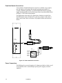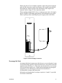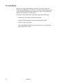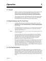
1
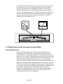
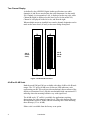
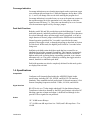
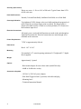
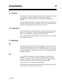
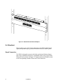
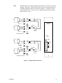
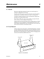
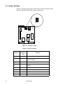
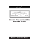
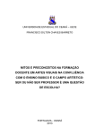
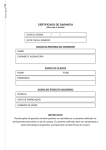
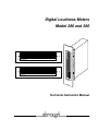
Digital Loudness Meters
Model 280 and 380
-39 -38 -37 -36 -35 -34 -33 -32 -31 -30 -29 -28 -27 -26 -25 -24 -23 -22 -21 -20 -19 -18 -17 -16 -15 -14 -13 -12 -11 -10 -9 -8 -7 -6 -5 -4 -3 -2 -1 0
-39 -38 -37 -36 -35 -34 -33 -32 -31 -30 -29 -28 -27 -26 -25 -24 -23 -22 -21 -20 -19 -18 -17 -16 -15 -14 -13 -12 -11 -10 -9 -8 -7 -6 -5 -4 -3 -2 -1 0
MODEL 280-D
U.S.A.
Model 280-D
-57 -54 -51 -48 -45 -42 -39 -36 -33 -30 -29 -28 -27 -26 -25 -24 -23 -22 -21 -20 -19 -18 -17 -16 -15 -14 -13 -12 -11 -10 -9 -8 -7 -6 -5 -4 -3 -2 -1 0
-57 -54 -51 -48 -45 -42 -39 -36 -33 -30 -29 -28 -27 -26 -25 -24 -23 -22 -21 -20 -19 -18 -17 -16 -15 -14 -13 -12 -11 -10 -9 -8 -7 -6 -5 -4 -3 -2 -1 0
MODEL 280-E
U.S.A.
0
–1
–2
–3
–4
–5
–6
–7
–8
–9
-10
-11
-12
-13
-14
-15
-16
-17
-18
-19
20
21
22
23
24
25
26
27
28
29
30
31
32
33
34
35
36
37
38
39
U.S
.A.
Model 280-E
0
–1
–2
–3
–4
–5
–6
–7
–8
–9
-10
-11
-12
-13
-14
-15
-16
-17
-18
-19
20
21
22
23
24
25
26
27
28
29
30
31
32
33
34
35
36
37
38
39
38
0-D
Technical Instruction Manual
Digital Loudness Meters
Model 280 and 380
April, 1999
Copyright © 1994 and 1999 by Dorrough Electronics, 20434
Corisco St., Chatsworth California, 91311.
PH 818.998.2824, FAX 818.998.1507.
Dorrough Electronics reserves the right to make changes and
improvements in product specifications without notice.
Introduction
1
1.1. Loudness Monitoring
Double Standards
For nearly 60 years the world has used two different standards for audio
monitoring. In the United States, the VU meter, introduced in 1937, was the
standard for level monitoring. In Europe, the PPM (Program Peak Meter)
was the standard.
0
20
0
-2
40
-1 0
60
80
100
5 -3 -2 -1 VU +1
+2
-7 +3
2
1
3
4
5
6
7
The VU meter is a quasi-average reading device. Basically a voltmeter
calibrated in power with ballistics chosen to represent early radio and film
program material, it was never intended to indicate the peak excursions
found in today’s program material.
The PPM addressed the limitations of the VU meter, but because it displays
and holds only the peak level of the waveform, the integration time of the
quasi-average program level is almost completely ignored.
Most contemporary studios have tried to solve their metering problems by
using both VU and PPM meters on the same source in an attempt to get the
maximum usable level out of a piece of program material. This has led to
cramped and overly complex metering bridges and panels, and does not
overcome the limitations of these systems. Even the switchable bar graph
meters offered as a solution by some console manufacturers suffer from the
same ballistic limitations.
Unification
In 1980, after years of hands-on experience and frustration with both
conventional VU and PPM metering, Dorrough research led to the
introduction of the Dorrough Model 40 Loudness Meter. By providing an
easy to understand display showing the relationship between integration of
RMS and peak level display, the model 40 was an overnight success. Today
the model 40 is regarded as the standard in audio monitoring and is used
throughout recording and broadcast facilities around the world.
Introduction
1
The Dorrough Loudness Meter gives you a much more accurate picture of
the actual energy content of audio program material than conventional
metering. By simultaneously displaying two ballistics, the Dorrough
Loudness Meter shows you the relationship between average and peak.
You need only adjust the program level until either the peak or persistence
reference is reached. This will result in the maximum level, regardless of
program content. Material with or without compression can easily be
matched for the same listening level.
0
20
-2
-25
0
40
-1 0
60
80
100
2
5 -3 -2 -1 VU +1
+2
-7 +3
-22
18
-20 -
3
4
5
6
7
1
4
-16 -1
A
N ORM
-12
-10
-8
-6
ANGE
ISTENCE R
L P E RS
-4
-2
0
+2
+4
+6
NORMA
L PEAK
LOUDNESS MONITOR
+8 +1
0 +1
2
+14
RANG
E
MODEL 40-A
1.2. Digital Audio and the Dorrough Loudness Meter
Into the Digital Domain
The Audio Engineering Society (AES), together with the European
Broadcasting Union (EBU), have established a digital audio interface
standard known as the AES/EBU interface. This standard provides robust
formats for the exchange of digital audio information between professional
audio devices, yet also provides flexibility for specialized applications. The
International Electrotechnical Commission (IEC) has also endorsed a
format based on the AES/EBU standard for consumer digital audio devices.
Briefly, the AES/EBU format standard defines how two channels of audio
information are periodically sampled, uniformly quantized and transmitted
over a twisted wire pair. Left and Right audio channels are multiplexed, and
the channel is self-clocking and self-synchronizing. The format is
independent of sampling frequency and can be used with any sampling
frequency including 32 kHz, 44.1 kHz, and 48 kHz, which are those
recommended by AES for PCM applications.
2
Introduction
New Challenges
The wider dynamic range provided by this standard also poses new
challenges in monitoring. The trend to obtain a “hotter” signal typically
involves more sophisticated processing and compression. The narrowing
gap between average level and peak level means more accurate monitoring
is necessary to obtain desired results.
Another important consideration in today’s digital recording and
broadcasting include monitoring the “crash point”, or the point of reaching
the maximum input level the system or equipment can handle.
The Dorrough Digital Level Meters have been designed to meet these needs
with unprecedented accuracy, flexibility and convenience in the Dorrough
tradition.
1.3. The Dorrough 280 and 380
The Dorrough model 280 and 380 Digital Loudness Monitors (DLMs)
provide the same basic functionality as the classic 40 series analog loudness
meter except that they accept a digital data signal and display two channels.
Horizontal or Vertical Mounting
The model 280 is designed for horizontal mounting while the model 380 is
designed for vertical mounting. Both models are offered with two scale
ranges, a standard 40 dB range (-D suffix), and an expanded 60 dB range
(-E suffix). Figure 1-1 illustrates the model 280 with both scale options,
while Figure 1-2 shows the model 380 with both scales.
-39 -38 -37 -36 -35 -34 -33 -32 -31 -30 -29 -28 -27 -26 -25 -24 -23 -22 -21 -20 -19 -18 -17 -16 -15 -14 -13 -12 -11 -10 -9 -8 -7 -6 -5 -4 -3 -2 -1 0
-39 -38 -37 -36 -35 -34 -33 -32 -31 -30 -29 -28 -27 -26 -25 -24 -23 -22 -21 -20 -19 -18 -17 -16 -15 -14 -13 -12 -11 -10 -9 -8 -7 -6 -5 -4 -3 -2 -1 0
MODEL 280-D
U.S.A.
Model 280-D
-57 -54 -51 -48 -45 -42 -39 -36 -33 -30 -29 -28 -27 -26 -25 -24 -23 -22 -21 -20 -19 -18 -17 -16 -15 -14 -13 -12 -11 -10 -9 -8 -7 -6 -5 -4 -3 -2 -1 0
-57 -54 -51 -48 -45 -42 -39 -36 -33 -30 -29 -28 -27 -26 -25 -24 -23 -22 -21 -20 -19 -18 -17 -16 -15 -14 -13 -12 -11 -10 -9 -8 -7 -6 -5 -4 -3 -2 -1 0
MODEL 280-E
U.S.A.
Model 280-E
Figure 1-1. 280 Front Vie
Introduction
3
Two Channel Display
As defined by the AES/EBU Digital Audio specification, two audio
channels (A and B) are encoded into the serial datastream. On the model
280, Channel A (corresponds to Left), is displayed on the top scale, while
Channel B (Right) is displayed on the lower scale. On the model 380,
Channel A is displayed on the left scale, and B on the right.
When multiple meters are installed in a console, channel designation can be
made on the meter bezel (if used), or the meter bridge front panel.
380-D
(40 dB
scale)
0
–1
–2
–3
–4
–5
–6
–7
–8
–9
-10
-11
-12
-13
-14
-15
-16
-17
-18
-19
20
21
22
23
24
25
26
27
28
29
30
31
32
33
34
35
36
37
38
39
U.S.A.
0
–1
–2
–3
–4
–5
–6
–7
–8
–9
-10
-11
-12
-13
-14
-15
-16
-17
-18
-19
20
21
22
23
24
25
26
27
28
29
30
31
32
33
34
35
36
37
38
39
380-D
0
–1
–2
–3
–4
–5
–6
–7
–8
–9
-10
-11
-12
-13
-14
-15
-16
-17
-18
-19
20
21
22
23
24
25
26
27
28
29
30
33
36
39
42
45
48
51
54
57
U.S.A.
0
–1
–2
–3
–4
–5
–6
–7
–8
–9
-10
-11
-12
-13
-14
-15
-16
-17
-18
-19
20
21
22
23
24
25
26
27
28
29
30
33
36
39
42
45
48
51
54
57
380-E
(60 dB
scale)
380-E
Figure 1-2. Model 380 Front Vie
40 dB or 60 dB Scale
Both the model 280 and 380 are available with either 40 dB or 60 dB scale
ranges. The “D” suffix (40 dB) uses 40 discrete LED indicators, each
representing one dB. This scale provides an absolutely linear cadence of the
display as a function of level, which is not obtainable with conventional VU
metering where the metering ballistics vary with signal level.
The 60 dB scale (“E” suffix) is available for applications requiring
observation of a wider range of signal levels. This scale also provides one
dB indications from 0 to -30dB, with the remaining nine LEDs indicating
three dB steps (-33 to -60 dB).
Either scale is available from the factory as an option.
4
Introduction
Overrange Indication
Overrange indication occurs when the input signal reaches a point one count
over maximum allowed input level. When this happens, the top three LEDs
(0, -1, and -2) all change color to red while tracking the program level.
Overrange indication is set at the factory to occur at the point one count over
the maximum signal level (the maximum level is the point at which the
signal becomes all binary 1’s). This point can alternately be set to 4 counts
over the maximum signal level by moving a jumper.
Peak Hold Functions
Both the model 280 and 380 provide three peak hold functions: 3-second
peak hold (normal), indefinite peak hold, and no peak hold. These functions
are selected through a three-position toggle switch (supplied), or if only a
single function is desired, jumper selected on the DLM main circuit board.
Normal operation (peak hold for 3-seconds) is provided at the center
position of the toggle switch, or through jumpering as described in Section
4 of this book. In this mode, the highest peak is held for 3-seconds before
being reset.
Indefinite peak hold retains the highest peak that has occurred for an
indefinite period while constantly resampling. This function is particularly
useful for unattended operation where the engineer wishes to record the
highest audio peak occurring during a mastering operation, or at a remote
transmitter site, etc. The peak is cleared by switching the toggle switch to
normal, then back to indefinite peak hold.
Peak hold operation may also be completely defeated. In this mode, peaks
are displayed in real time.
1.4. Specifications
Compatibilit
Conforms to all formats defined within the AES/EBU Digital Audio
specification, including IEC 958, S/PDIF, and EIAJ CP-340 interface
standards. These standards include professional 24-bit and consumer 16-bit
formats. Sampling frequencies include 32 kHz, 44.1 kHz, and 48 kHz.
Signal Interface
RS-422 levels over 75-ohm single-ended and 110-ohm balanced inputs.
Transformer isolated (as dictated by the EBU specification) with series DC
blocking capacitor on input and output. A buffered feed-through is also
provided. These signals are not polarized.
Scales
“D:” 40 dB in one-dB steps
“E:” 60 dB in one dB steps from 0 to -30 dB, and 3-dB steps from -33 to
-60 dB.
Introduction
5
Accuracy (both scales)
Worst case error: +1.4% to -0.8% of full scale. Typical: better than 0.35%
of full scale error.
Peak Hold Functions
Normal (3-Second Peak Hold), Indefinite Peak Hold, or no Peak Hold.
Overrange Indication
Top/rightmost 3 LEDs change color to red while tracking the program level
peaks when the overrange trigger point is reached. The trigger point is
jumper selectable between 1-count over (factory default), or 4-counts over
the maximum input level.
Electrical Connections
All signal, power, and peak hold functions are made to the unit through an
eight-pin Euroconnector. Electrical connections are made through screw
terminals in the connector.
Power Requirements
7 VDC at approximately 600 mA.
Dimensions
Bezel: 1.45” x 5.00”.
Mounting
Fits standard 1.45” console opening (minimum 5.0” height and 5.5” depth).
Bezel supplied.
Weight
Approximately 1 pound.
Options
– Rack mount adapter for one to three units (model 280 only).
– 40 dB or 60 dB scale overlay.
Accessories Supplied
– 120VAC or 220VAC power adapter
– Peak Hold Toggle Switch (3-position) with cable and plug
– Mounting bezel
– Technical Instruction Manual
6
Introduction
Installation
2
2.1. General
Installation of the DLM is straightforward and easy. When multiple DLMs
are installed in a console the use of a common power supply is
recommended. Installation procedures are provided in the following
sections.
Your Dorrough model 280 or 380 Digital Loudness Meter is warranted for
a period of one year from date of purchase. Be sure to complete and return
the Warranty Registration Form to activate the warranty.
2.2. Unpacking
All Dorrough Digital Loudness Meters are carefully packed at the factory,
however, if any damage is evident, retain the packaging and notify the
transit carrier and your local distributor about your claim.
Once you are satisfied with the physical integrity of the unit, proceed with
the installation procedure.
2.3. Mounting
280
The model 280 is designed for horizontal mounting in a console or rack. For
console installation, the unit mounts in a standard 1.45” by 5.0” cutout. If
you intend to install the unit in a rack, a optional rack adapter are available
as shown in Figure 2-1. Contact the factory or your sales representative for
ordering information.
380
The model 380 is designed for vertical mounting in a console having
standard 1.45” by 5.0” cutouts. If plan to install the meter in a custom
console or equipments and do not wish to use the bezel supplied, cutout
dimensions can be taken from the inside opening of the bezel.
Contact the factory for alternate mounting options.
An illustration of detailed measurements useful for mounting the model 380
in a console is provided at the rear of this book.
Installation
7
-57 -54
-57 -54
-51 -48
-51 -48
-45 -42
-45 -42
-39 -36
-39 -36
-33 -30
-33 -30
-29 -28
-29 -28
-27 -26
-27 -26
-25 -24
-25 -24
-23 -22
-23 -22
-21 -20
-19 -18
-17 -16
-15 -14
-13 -12
-11 -10
-9 -8
-7 -6
-5 -4
-3 -2
-1 0
-21
-20 -19
MOD
-18 -17
EL 280-E
-57 -54
-16 -15
-14 -13
-12 -11
-51 -48
-45 -42
-39 -36
-10 -9
-8 -7
-6 -5
-4 -3
-2 -1
0
U.S.A
.
-57 -54
-51 -48
-45 -42
-39 -36
-33 -30
-33 -30
-29 -28
-29 -28
-27 -26
-27 -26
-25 -24
-25 -24
-23 -22
-23 -22
-21 -20
-19 -18
-17 -16
-15 -14
-13 -12
-11 -10
-9 -8
-7 -6
-5 -4
-3 -2
-1 0
-21
-20 -19
MOD
-18 -17
EL 280-E
-57 -54
-16 -15
-14 -13
-12 -11
U.S.A
.
-57 -54
-57 -54
-51 -48
-51 -48
-45 -42
-45 -42
-39 -36
-39 -36
-33 -30
-33 -30
-51 -48
-45 -42
-39 -36
-10 -9
-8 -7
-6 -5
-4 -3
-2 -1
0
-57 -54
-51 -48
-45 -42
-39 -36
-33 -30
-33 -30
-29 -28
-29 -28
-27 -26
-27 -26
-25 -24
-25 -24
-23 -22
-23 -22
-21 -20
-19 -18
-17 -16
-29 -28
-29 -28
-27 -26
-27 -26
-25 -24
-25 -24
-23 -22
-23 -22
-21 -20
-19 -18
-17 -16
-15 -14
-13 -12
-11 -10
-15 -14
-13 -12
-11 -10
-9 -8
-7 -6
-5 -4
-3 -2
-1 0
-21
-20 -19
MOD
-18 -17
EL 280-E
-16 -15
-14 -13
-12 -11
-10 -9
-8 -7
-6 -5
-4 -3
-2 -1
0
U.S.A
.
-9 -8
-7 -6
-5 -4
-3 -2
-1 0
-21
-20 -19
MOD
-18 -17
EL 280-E
-16 -15
-14 -13
-12 -11
-10 -9
-8 -7
-6 -5
-4 -3
-2 -1
0
U.S.A
.
Figure 2-1. Model 280 Rack Mount Adapters
2.4. Electrical
There are three types of electrical connections to the DLM: digital signal
input (and optional output), peak hold function selection, and DC power.
Signal Connection
The DLM is designed to operate with either professional balanced input
lines using a shielded twisted pair, or unbalanced lines using coaxial cable.
Wiring for each is shown in Figure 2-2. Signal connections should be made
to the corresponding terminal of the meter’s Euroconnector.
8
Installation
Note:
The DLM provides a buffered digital signal output, which may be used for
bridging. This feature is particularly useful when connecting unbalanced
consumer equipment with low signal level outputs (< 500 mV) to professional balanced lines. In either case, the buffered digital output signal is
approximately 4 volts.
Input
110 Ohm
Woodland Hills, Ca 91364
Made in U.S.A.
110 Ohm
Buffered
Output
RS 422
Driver
Balanced Systems
POWER
7 – 12 VDC
PEAK
HOLD
Input
110 Ohm
BUFFERED
DIGITAL OUT
GROUND
DIGITAL IN
110 Ohm
GROUND
V–
Buffered
Output
V+
RS 422
Driver
Un-Balanced Systems
Figure 2- . Digital Signal Connection
Installation
9
Peak Hold Switch Connections
Two methods of Peak Hold function control are available. If you wish to
have the option of selecting either normal operation (peak hold for 3
seconds), indefinite peak hold, or peak hold disabled, the three position
toggle switch supplied (or its electrical equivalence) must be installed. Refer
to Figure 2-3 for switch wiring details.
For applications where only one of these three functions is needed, the
desired function can be “hardwired” by moving a jumper on the meter’s
main circuit board. Refer to Section 4 for jumper location and selection
details.
Woodland Hills, Ca 91364
Made in U.S.A.
POWER
7 – 12 VDC
PEAK
HOLD
BUFFERED
DIGITAL OUT
GROUND
DIGITAL IN
SPDT
Three Position
GROUND
V–
V+
Permanent
Peak Hold
Auto Reset
Peak Hold
Peak Hold
Disabled
Figure 2-3. Peak Hold Switch Connection
Power Connections
The DLM may be powered using the AC adapter provided, or in the case of
several DLMs, from a common high capacity power supply (customer
supplied).
10
Installation
When using the AC power adapter supplied, connect the positive lead (the
lead with the white tracer strip) to the positive DC terminal on the DLM’s
Euroconnector, and the negative lead (solid black) to the negative DC
terminal. Refer to Figure 2-4 for connection details.
When suppling multiple DLM’s from a common power source, the supply
must be capable of furnishing approximately 600 milliamperes per meter.
Observe polarity when connecting the power supply leads to the DLM.
Woodland Hills, Ca 91364
Made in U.S.A.
POWER
7 – 12 VDC
PEAK
HOLD
BUFFERED
DIGITAL OUT
GROUND
DIGITAL IN
GROUND
V–
V+
Figure 2-4. Power Supply Connection
Overrange Set Point
Overrange indication is jumper set at the factory to occur at the point 1 count
over the maximum signal level (the maximum level is the point at which the
signal becomes all binary 1’s). This point can alternately be set to 4 counts
over the maximum signal level. Consult the documentation for the digital
equipment you are monitoring to determine the manufacturer’s
recommended overrange indication point.
Information on changing the Overrange set point to “4-under” is provided
in section 4 of this book.
Installation
11
2.5. Initial Setup
Because the signal and monitoring electronics are entirely digital, no
calibration or adjustments are necessary. To verify operation, apply a tone
(in the AES/EBU digital format) to the DLM’s input. The meter should
indicate precisely the level of the signal.
If you do not see an indication on the DLM, perform the following:
12
•
recheck your connections on the Euroconnector
•
ensure the Euroconnector is properly seated unto the DLM
•
verify DC power is present
•
verify a digitally encoded tone is present and is at a level within the
range of the DLM’s scale.
Installation
Operation
3
3.1. General
Outside of manually setting the peak hold function desired, operation of the
DLM is automatic. Because the AES/EBU standard requires format
information to be embedded within the data frame, the DLM contains
circuitry to automatically match its configuration to the format detected.
This means that consumer 16-bit or professional 24-bit digital audio formats
having sampling rates of 32 kHz, 44.1 kHz, or 48 kHz, are automatically
detected and correctly displayed on the DLM (patent pending).
3.2. Digital Headroom and The Crash Point
Overrange indication occurs when the input signal reaches a level just
slightly above the maximum allowed input level. When this happens, the top
three LEDs (0, -1, and -2) all change color to red while tracking the program
material peaks.
Overrange indication is set at the factory to occur at the point one count over
the maximum signal level (the maximum level is the point at which the
signal becomes all binary 1’s).
Note:
This point can alternately be set to 4 counts over the maximum signal level
by moving a jumper.
Practically, when you see the overrange indication occur, the offending
peak was .0008 dB below the maximum signal input level allowed by the
AES/EBU format (24-bit). Consult the documentation for the digital
equipment you are monitoring to determine the point at which the
manufacturer expects overrange indication to occur.
How a particular equipment deals with a level that hits the crash point may
be another consideration in determining the overrange trigger point, and
maximum operating peak level. Some equipment types are more tolerant of
input level “crashes” than others (i.e., one equipment may hold at all 1’s,
while another may rollover to all 0’s). In this example, the latter equipment
requires special monitoring attention.
3.3. The Peak Hold Switch
Both the model 280 and 380 provide three types of peak hold functions:
normal operation (3-second peak hold), indefinite peak hold, and peak hold
disabled. These function are selected through a three-position toggle switch
(supplied). Alternately, if operation of only one of these functions is desired,
the function can be selected by moving a jumper on the DLM main circuit
board.
Operation
13
Normal (3-Second Peak Hold)
Normal operation (peak hold functions disabled) is provided at the center
position of the toggle switch, or through jumpering as described in Section
4 of this book. In this mode, the highest peak is held for a period of three
seconds before resetting.
Indefinite Peak Hold
Indefinite peak hold retains the highest peak that has occurred for and
indefinite period while constantly resampling. The peak is cleared by
switching the toggle switch to normal, then back to the indefinite peak hold
position.
This function is particularly useful for unattended operation where, for
example, an engineer wishes to record the highest audio peak occurring at a
remote transmitter site, etc.
Peak Hold Disabled
In this mode, peaks are displayed as they occur in real time and are not held.
14
Operation
Maintenance
4
4.1. General
Because the signal and monitoring electronics are entirely digital, no
calibration or adjustments are necessary.
Generally, the DLM requires no periodic maintenance other than perhaps
wiping any dust accumulation from the scale with a soft damp cloth.
4 miniature incandescent lamps provide scale illumination. Replacement
procedures are described in this section.
The 40 dB or 60 dB scale overlay is also available as an option from the
factory, when you wish to change the display range.
Jumpers on the main circuit board may require resetting at the time of initial
installation for specific applications. For most applications, however, the
factory jumper settings should be used. The following section describes the
jumper functions and their corresponding settings.
4.2. Cover Removal
In order to gain access to the jumpers, scale illumination lamps, or internal
test points, unplug the Euroconnector and remove the DLM from its mounting surface. Place the unit on a flat surface with the Euroconnector down, or
the left side up as shown in Figure 4-1. Remove the four self-tapping metal
screws (two on each side), and lift off the cover.
Remove These
Screws
Remove These
Screws
LEFT COVER
Figure 4-1. Cover Removal
Maintenanc
15
4.3. Jumper Settings
Figure 4-1 illustrates the jumpers on the DLM’s main circuit board, while
the following table defines their settings and functions.
0 1
JP0
JP1
JP2
JP3
JP0
JP1
JP2
JP3
XFORMER
XFORMER
Figure 4-2. Jumper Locations
Table 4-1. Jumper Functions
Jumper
Across
Center Pin
and:
JP0
0*
Overrange indication trigger = 1 count over
1
Overrange indication trigger = 4 counts over
(*factory default)
0
Indefinite peak hold
1*
3-Second peak hold auto reset (*factory
default)
0
Peak hold disabled
1
Peak hold enabled (factory default)
0
40 dB scale (factory set)
1
60 dB scale (factory set)
JP1
JP2
JP3
16
Function
Maintenance
4.4. Lamp Replacement Procedures
Scale illumination is provided by two miniature incandescent lamps on each
side of the scale (four total). These lamps are operated significantly below
their normal rating to ensure long life. If, however, it becomes necessary to
replace one more of these lamps, replacements may be obtained from your
local electronics supply distributor, or from Dorrough Electronics. The
lamp has the following ratings:
Type:
CW85
Size:
T1
Voltage:
8V
Current:
50 mA
Light Output: .095 candlepower
Base:
Straight wires, solder in.
Use a low wattage soldering iron to remove the defective lamp and to connect the new lamp to the circuit board. Remove any excess solder before reassembling.
4.5. Return Procedures
Your Dorrough model 280 or 380 Digital Loudness Meter is warranted for
a period of one year from date of purchase. Be sure to complete and return
the Warranty Registration Form to activate the warranty.
In the event it is necessary to return your model 280 or 380 to the factory for
service, in or out of warranty, you must first obtain a Return Material Authorization (RMA) number from Dorrough Electronics at (818) 998-2824 or
FAX at (818) 998-1507. If the original shipping materials are not available,
be sure the unit is adequately packed.
Maintenanc
17
18
Maintenance