1
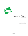
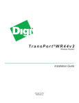
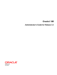
User Manual
for 1x RS-232/422/485 port
to 1x or 2x 10/100TX Device Server
and 1x RS-232/422/485 port
to 1x 100FX Device Server
Version Beta 1.04
January 2008
MICROSENS User Manual
Device Server RS-232/422/485 Port to 1x or 2x 10/100TX
and Device Server RS-232/422/485 Port to 1x 100FX
Notice
This manual contents are based on the below table listing software
kernel version, hardware version, and firmware version. If the device
functions have any different from the manual contents description,
please contact the local sale dealer for more information.
Firmware Version
V1.05j
Kernel Version
V1.00
Hardware Version
V1.00
ii
MICROSENS User Manual
Device Server RS-232/422/485 Port to 1x or 2x 10/100TX
and Device Server RS-232/422/485 Port to 1x 100FX
FCC Warning
This Equipment has been tested and found to comply with the limits for a Class-A
digital device, pursuant to Part 15 of the FCC rules. These limits are designed to
provide reasonable protection against harmful interference in a residential
installation. This equipment generates uses and can radiate radio frequency
energy and, if not installed and used in accordance with the instructions, may
cause harmful interference to radio communications. However, there is no
guarantee that interference will not occur in a particular installation. If this
equipment does cause harmful interference to radio or television reception,
which can be determined by turning the equipment off and on, the user is
encouraged to try to correct the interference by one or more of the following
measures:
Reorient or relocate the receiving antenna.
Increase the separation between the equipment and receiver.
Connect the equipment into an outlet on a circuit different from that to
which the receiver is connected.
Consult the dealer or an experienced radio/TV technician for help.
CE Mark Warning
This is a Class-A product. In a domestic environment this product may cause
radio interference in which case the user may be required to take adequate
measures.
iii
MICROSENS User Manual
Device Server RS-232/422/485 Port to 1x or 2x 10/100TX
and Device Server RS-232/422/485 Port to 1x 100FX
Content
Introduction............................................................................................................1
Features .......................................................................................................................1
Software Feature.........................................................................................................2
Accessories ...................................................................................................................4
Hardware Description ............................................................................................5
Physical Dimension ......................................................................................................5
Top & Bottom ..............................................................................................................5
Pin Assignment.....................................................................................................7
DIP Switch.............................................................................................................8
LED Indicators ..............................................................................................................8
Wiring the Power Inputs...........................................................................................10
DIN-Rail Mounting .............................................................................................11
Wall Mount Plate Mounting.....................................................................................12
Installation Steps .......................................................................................................13
Power On ...................................................................................................................13
X-Ware Utilities.....................................................................................................14
Quick Install ...............................................................................................................14
Web-Based Management .....................................................................................19
Server Configuration.................................................................................................19
System Information............................................................................................19
SNTP Configuration............................................................................................20
IP Configuration .................................................................................................21
User Authentication...........................................................................................22
Port Serial Setting......................................................................................................23
Serial Setting ......................................................................................................23
Port Profile .........................................................................................................24
Service Mode ......................................................................................................24
Virtual COM.................................................................................................25
TCP Server....................................................................................................26
TCP Client ....................................................................................................27
UDP ..............................................................................................................28
Management .............................................................................................................29
iv
MICROSENS User Manual
Device Server RS-232/422/485 Port to 1x or 2x 10/100TX
and Device Server RS-232/422/485 Port to 1x 100FX
Access IP Control List..........................................................................................29
SMTP/SNMP Configuration ................................................................................30
Event Notification ..............................................................................................31
Save/Restart ...............................................................................................................33
Technical Specification ........................................................................................34
SNMP MIB II and RS232 Like Support .................................................................36
RS232 Pin Assignment .........................................................................................38
v
MICROSENS User Manual
Device Server RS-232/422/485 Port to 1x or 2x 10/100TX
and Device Server RS-232/422/485 Port to 1x 100FX
Introduction
Device Server is a clever one RS-232/422/485 port to Ethernet port(s). The
redundant Ethernet ports can auto-recover rapidly when link breaks.
The serial port of devices such as POS terminal, digital display, medical
measurement etc. can be connected to the Device Server over Ethernet just as
locally attached. It provides more powerful ability for accessing multiple hosts
and eliminates the limitation of transmission distance in Ethernet.
Features
RJ-45: 10/100Mbps (1 RS-232/422/485 port to 1 or 2 10/100TX Device Server),
100FX: 100Mbps (1 RS-232/422/485 port to 1 100FX Device Server)
Built-in 1.5KV magnetic isolation
1 RS-232/422/485 port, male DB-9, DIP switch selectable
DIP switch-controlled mode selection: RS-232, RS-422, RS-485 two-wire,
RS-485 four-wire
Serial Line Protection: 15 KV ESD for all signals
Up to 460.8Kbps transmission rate
RoHS regulatory approval
Support HTTPS, SSH v2, SSL v3**
4 hosts—Virtual Com, TCP Server, TCP Client—simultaneous connections
Virtual Com/TCP Server/TCP Client/UDP/Serial Tunnel serial mode with
advanced setting
Support Email/SNMP trap/Beeper event notification
X-Ware utility for windows NT/2000/XP/2003
Device discovery
Auto IP report
Device setting (run time change, no rebooting)
Access Control List
Device monitoring
Virtual Com/TTY Drivers for Windows NT/2000/XP/2003, Linux real TTY driver
** Optional
1
MICROSENS User Manual
Device Server RS-232/422/485 Port to 1x or 2x 10/100TX
and Device Server RS-232/422/485 Port to 1x 100FX
Software Feature
Management
Supports Web, X-ware Utilities and Telnet
interface for configuration
ICMP, IP, TCP, UDP, DHCP, BootP, ARP/RARP,
Protocols
Telnet, RTelnet, DNS, SNMP MIB II, HTTP, SMTP,
SNTP
Virtual Com/TCP Server/TCP Client/UDP/Serial
Tunnel serial mode with advanced setting:
Serial mode
TCP Alive Check Timeout
Inactivity Timeout
Delimiter for Data Packing
Force TX Timeout for Data Packing
Security
HTTPS, SSH v2, SSL v3(data encryption)**
4 Hosts
simultaneous
Virtual Com/TCP Server/TCP Client(row data only)
connection
Email/SNMP trap/Beeper
SNMP Trap
Cold/Warm Start
DSR, DCD Changed
Event notification
IP Changed
Authentication Fail
SNMP Response
System MIB
Interface MIB
2
MICROSENS User Manual
Device Server RS-232/422/485 Port to 1x or 2x 10/100TX
and Device Server RS-232/422/485 Port to 1x 100FX
ICMP, IP, TCP MIB
UDP MIB
RS-232 MIB
X-ware for Windows NT/2000/XP/2003/Vista
Device discovery
Auto IP report
Device setting(run-time change, no
rebooting)
Utilities
Access Control List
Group setting
Device monitoring
Serial port monitoring
Log info
Group Firmware update batch
Virtual Com/TTY
Drivers (WDM mode,
Windows NT/2000/XP/2003, Linux real TTY Driver
configuration in
Windows 95/98, Unix Fixed TTY driver by
windows devices
request**
manager)
Serial API Function
Port Control, Input/Output Data, Port Status
Inquiry
** Optional
3
MICROSENS User Manual
Device Server RS-232/422/485 Port to 1x or 2x 10/100TX
and Device Server RS-232/422/485 Port to 1x 100FX
Accessories
Unpack the accessories and verify them against the checklist below.
Wall-mounted kit
DIN rail
User manual & X-Ware Utility
Wall-mounted Kit
Din-Rail
User Manual & X-Ware Utility
Accessories
Compare the accessories with the standard checklist above. IF any item is missing
or damaged, please contact your local dealer for service.
4
MICROSENS User Manual
Device Server RS-232/422/485 Port to 1x or 2x 10/100TX
and Device Server RS-232/422/485 Port to 1x 100FX
Hardware Description
This section mainly describes the hardware of Device Server.
Physical Dimension
The physical dimensions of Device Server are 72mm(W) x 100mm(D) x
32mm(H)
Top & Bottom
The top & bottom of the Device Server picture are shown as below.
PWR1: Insert the positive and negative wires into the V+ and V- holes to the
PWR1 on the terminal block connector.
PWR2: Insert the DC power supply adapter to PWR2 DC jack with 12V or 24V. In
the beginning the power LED is red, and after the system is successful initialized,
it turns green. In addition, if PWR1 and PWR2 are connected at the same while,
the device server will work with the higher connected voltage.
Ethernet (1 RS-232/422/485 port to 1 10/100TX Device Server): 10/100Mbps
redundant Ethernet RJ-45 ports both support Auto MDI/MDIX.
Top side of 1 RS-232/422/485 port to 1 10/100TX Device Server
5
MICROSENS User Manual
Device Server RS-232/422/485 Port to 1x or 2x 10/100TX
and Device Server RS-232/422/485 Port to 1x 100FX
Eth1, Eth2 (1 RS-232/422/485 port to 2 10/100TX Device Server): 10/100Mbps
redundant Ethernet RJ-45 port supports Auto MDI/MDIX.
Top side of 1 RS-232/422/485 port to 2 10/100TX Device Server
TX, RX (1 RS-232/422/485 port to 1 100FX Device Server): IEEE802.3 u
100Base-FX, SC type connector in multi mode (2 km) or single mode (30 km).
Top side of 1 RS-232/422/485 port to 1 100FX Device Server
Reset: Press the reset button about 10 seconds for restoring factory default.
Release it when power LED starts to blink in red. As the power LED becomes
green, the device server has loaded the factory default and is ready to work.
6
MICROSENS User Manual
Device Server RS-232/422/485 Port to 1x or 2x 10/100TX
and Device Server RS-232/422/485 Port to 1x 100FX
Serial Port: It’s an RS-232/422/485 port male DB-9 and 15KV ESD for all signals.
DIP Switch: 4 modes available for RS-232, RS-422, RS-485 two-wire and RS-485
four-wire.
Bottom side of Device Server
Pin Assignment
Pin
RS-232
RS-422
1
DCD
RXD-
RXD-
2
RXD
RXD+
RXD+
3
TXD
TXD+
TXD+
DATA+
4
DTR
TXD-
TXD-
DATA-
5
GND
GND
GND
GND
6
DSR
7
RTS
8
CTS
9
RI
Number
RS-232 mode act as DTE
7
RS-486(4-wire) RS-485(2-wire)
MICROSENS User Manual
Device Server RS-232/422/485 Port to 1x or 2x 10/100TX
and Device Server RS-232/422/485 Port to 1x 100FX
DIP Switch
DIP 1
DIP 2
120Ω Termination Configuration
ON
ON
120Ω Terminator for Long Distance 4-wire RS-485/RS-422
ON
OFF
–
OFF
ON
120Ω Terminator for Long Distance 2-wire RS-485
OFF
OFF
No terminator for RS-232/485 (short distance)
LED Indicators
The LED Indicators gives real-time information of systematic operation status. The
following table provides descriptions of LED status and their meaning.
LED
PWR1
Meaning
Status
Red On
Red
Blinking
Power is on and booting up.
Indicates an IP conflict, or DHCP or
BOOTP server does not respond
properly.
Green On
Power is on and works functionally
Green
Located by Administrator’s Location
Blinking
function.
8
MICROSENS User Manual
Device Server RS-232/422/485 Port to 1x or 2x 10/100TX
and Device Server RS-232/422/485 Port to 1x 100FX
Off
Red On
Red
Blinking
No device attached or Link is
disconnected
Power is on and booting up.
Indicates an IP conflict, or DHCP or
BOOTP server does not respond
properly.
PWR2
Green On
Power is on and works functionally
Green
Located by Administrator’s Location
Blinking
function.
Off
Eth LNK/ACT
Orange
(1xRS-232/422/
Blinking
485 port to 1
Green
10/100TX
Blinking
Device Server)
Off
Eth1, Eth2
Orange
LNK/ACT
Blinking
(1x RS-232/422/
Green
485 port to 2
Blinking
No device attached or Link is
disconnected.
10 Mbps Ethernet connection
100Mbps Ethernet connection
Ethernet cable is not connected
10 Mbps Ethernet connection
100Mbps Ethernet connection
10/100TX
Device Server)
Fiber
LNK/ACT
Off
Green
Blinking
Ethernet cable is not connected
100Base Fiber connection
(1xRS-232/422/
485 port to 1
100FX Device
Off
Fiber cable is not connected or no work
Orange
Serial port is receiving data.
Server)
TX/RX
9
MICROSENS User Manual
(1xRS-232/422/
Device Server RS-232/422/485 Port to 1x or 2x 10/100TX
and Device Server RS-232/422/485 Port to 1x 100FX
Green
Serial port is transmitting data.
485 port to 1
100FX Device
Off
Server)
No data is being transmitted or received
through the serial port.
Wiring the Power Inputs
Please follow the below steps to insert the power wire.
G
V-
V+
1. Insert the positive and negative wires into the V+
and V- contacts on the terminal block connector.
2. To tighten the wire-clamp screws for preventing the
DC wires to loose.
[NOTE] The wire range of terminal block is from 12 – 24 AWG.
10
MICROSENS User Manual
Device Server RS-232/422/485 Port to 1x or 2x 10/100TX
and Device Server RS-232/422/485 Port to 1x 100FX
DIN-Rail Mounting
The DIN-Rail is screwed on the device server when out of factory. If the DIN-Rail is
not screwed on the device server, please see the following pictures to screw the
DIN-Rail on the device server. Follow the below steps to hang the device server.
Device Server
1.
First, insert the top of DIN-Rail into the track.
11
MICROSENS User Manual
Device Server RS-232/422/485 Port to 1x or 2x 10/100TX
and Device Server RS-232/422/485 Port to 1x 100FX
2.
Then, lightly push the DIN-Rail into the track.
3.
Check if the DIN-Rail is tightened on the track or not.
4.
To remove the device server from the track, reverse steps above.
Wall Mount Plate Mounting
Follow the below steps to mount the device server with wall mount
plate.
1. Remove the DIN-Rail from the device server; loose the screws to remove the
DIN-Rail.
2. Place the wall mount plate on the rear panel of the device server.
3. Use the screws to screw the wall mount plate on the device server.
4. Use the hook holes at the corners of the wall mount plate to hang the device
server on the wall.
5. To remove the wall mount plate, reverse steps above.
Screwing the wall mount plate
on the device server
12
MICROSENS User Manual
Device Server RS-232/422/485 Port to 1x or 2x 10/100TX
and Device Server RS-232/422/485 Port to 1x 100FX
Installation Steps
1. Unpack the device server
2. Check if the DIN-Rail is screwed on the device server or not. If the DIN-Rail is
not screwed on the device server, please refer to DIN-Rail Mounting section
for DIN-Rail installation. If you want to wall mount the device server, then
please refer to Wall Mount Plate Mounting section for wall mount plate
installation.
3. Power on the device server. Please refer to the Wiring the Power Inputs
section for knowing the information about how to wire the power. The power
LED on the device server will light up. Please refer to the LED Indicators
section for indication of LED lights.
4. Prepare the twisted-pair, straight through Category 5 cable for Ethernet
connection.
5. Insert one side of RJ-45 cable (category 5) into the device server Eth1 or Eth2
port and another side of RJ-45 cable (category 5) to the PC or NB’s Ethernet
port. The Eth1 or Eth2 LED on the device server will light up when the cable is
connected with the PC or NB. Please refer to the LED Indicators section for
LED light indication.
Power On
Connect the power adapter to PWR1 or PWR2 socket on the top side of the device
server. The other side of power cord connects to the power outlet. The internal
power works with DC in the voltage range of 12-48V. Check the power indicator
on the front panel to see if power is properly supplied.
13
MICROSENS User Manual
Device Server RS-232/422/485 Port to 1x or 2x 10/100TX
and Device Server RS-232/422/485 Port to 1x 100FX
X-Ware Utilities
Device server supplies a powerful application, which is so-called “X-Ware” to
manage multiple devices.
This segment is intended to guide you through the steps to install the Windows
application—“X-Ware”.
Quick Install
X-Ware is an easy-to-use utility with auto device discovery in a LAN or adding
devices on the public network. All of the configurations on the serial server can
be done in the X-ware. You can also apply configurations of one serial server to
the others. This document shows you how to quick install the software. Being
aware of the full functions and configurations description, please refer to the
X-Ware user manual.
Install X-Ware
1. Insert the CD to run the program. If the setup program does not run
automatically, double-click the X-Ware setup program icon to install.
14
MICROSENS User Manual
Device Server RS-232/422/485 Port to 1x or 2x 10/100TX
and Device Server RS-232/422/485 Port to 1x 100FX
2. When the installation is completed, click OK button.
3. After you have clicked OK button, a check-box window shows up. To
mark the two check boxes for launching X-Ware immediately or later.
15
MICROSENS User Manual
Device Server RS-232/422/485 Port to 1x or 2x 10/100TX
and Device Server RS-232/422/485 Port to 1x 100FX
4. X-Ware will broadcast the network and search all available device server
units in the network.
The default parameters are:
IP address: 192.168.161
Login: admin
Password: microsens
Mark the check box of the new devices and click Add button for further
configuration.
16
MICROSENS User Manual
Device Server RS-232/422/485 Port to 1x or 2x 10/100TX
and Device Server RS-232/422/485 Port to 1x 100FX
5. Click on the tree menu in the left field, “X-Ware” ”Device
List” ”192.168.16.1” ”port1”, to configure the serial parameters such
as: Port Alias, Baudrate, Parity, Data Bits, Stop Bits, Flow Control, interface
and performance.
17
MICROSENS User Manual
Device Server RS-232/422/485 Port to 1x or 2x 10/100TX
and Device Server RS-232/422/485 Port to 1x 100FX
6. Change to “Service Mode” tab, and select the service mode to be Virtual
COM Mode. Then press “Map Virtual COM” button to map the port onto the
COM port.
Now you’ve completed the configuration setting with Virtual mode.
18
MICROSENS User Manual
Device Server RS-232/422/485 Port to 1x or 2x 10/100TX
and Device Server RS-232/422/485 Port to 1x 100FX
Web-based Management
Besides using X-Ware Utilities, you can also manage the device server via
Web-HTTPS and the SSH console.
The HTTPS is a security protocol that provides communication privacy over
Internet. The HTTPS packets transmitted between the device server and PC would
be encrypted.
The SSH allows users to securely login to remote host computers, to execute
commands safely in a remote computer, to securely copy remote files and to
provide secure encrypted and authenticated communications between two
non-trusted hosts.
When the device server has been configured with proper IP address and the web
management is enabled, you can use web browser to make further
configurations.
Type device server’s IP address in the URL, for example https://192.168.16.1 (Note:
you cannot just type http://, this is not allowed in HTTPS. Your should type
https://).
Key in the IP address in URL
Server Configuration
Server Configuration contains System Information, SNTP Configuration, IP
Configuration and User Authentication.
System Information
This page shows the information of the device server.
System Name: The model name of the device server.
IP Address: The IP address of the device server; the default IP is 192.168.16.1.
19
MICROSENS User Manual
Device Server RS-232/422/485 Port to 1x or 2x 10/100TX
and Device Server RS-232/422/485 Port to 1x 100FX
MAC address: The unique hardware address assigned by manufacture.
Firmware Version: The firmware version of the device server.
MS655400
00:60:A7:XX:XX:XX
System Information lists the basic information of this device server.
SNTP Configuration
MS655400
SNTP Configuration page
SNTP Configuration configures Server name, Time Server, and Telnet console
enable/disable.
Name: The Name of the device server.
20
MICROSENS User Manual
Device Server RS-232/422/485 Port to 1x or 2x 10/100TX
and Device Server RS-232/422/485 Port to 1x 100FX
Time:
SNTP: Enable or disable SNTP function to get the time from the SNTP
server.
Time Zone: Set the local time zone of the device server.
Local Time: Set the current time of the device server.
Time Server: The location and port of the time server.
Console:
Telnet Console: Enable or disable the telnet console.
IP Configuration
This page allows user to set the related configuration of the device server in
network.
IP Configuration: Select the assigning solution of IP configuration which is
assigned by DHCP/BOOTP or Static.
IP Address: Assign the IP address that the network is using.
Netmask: Assign the subnet mask of the IP address.
Gateway: Assign the network gateway for the device server. The default
gateway is 192.168.16.1.
DNS Server1: Assign the primary DNS IP address.
DNS Server2: Assign the secondary DNS IP address.
Auto IP Report
Auto Report to IP: Assign an IP to report the final alive check.
Auto Report to TCP Port: Assign the port number.
Auto Report Interval: Set the interval period for Auto report.
Ethernet Mode
Ethernet mode: The 1 RS-232/422/485 port to 2 10/100TX Device Server
supports the choice of RJ-45 ports for being used as a pair of redundant
port. If you mark the radio group item of “Redundant”, only one of the
two RJ-45 ports is active. When the active RJ-45 port fails, the other one
will be active to take over the work. While you mark the radio group
item of “Switch”, the two RJ-45 ports are used as general switching
ports.
21
MICROSENS User Manual
Device Server RS-232/422/485 Port to 1x or 2x 10/100TX
and Device Server RS-232/422/485 Port to 1x 100FX
IP Configuration page
User Authentication
Change web management login password. You have to key in the old password
first, and then key in the new password into “New Password” and “Confirm New
Password” columns.
User Authentication page
22
MICROSENS User Manual
Device Server RS-232/422/485 Port to 1x or 2x 10/100TX
and Device Server RS-232/422/485 Port to 1x 100FX
Port Serial Setting
Port Configuration includes Serial Setting, Port Profile and Service Mode.
Serial Setting
Port page
This page allows user to assign Serial Setting parameters, such as baud rate, data bits,
stop bits, parity, and flow control etc.
Port Alias: Give an alias name to the port to hint the connected device.
Interface: 4 type for selecting–RS232 / RS422 / RS485 (2-wires) / RS485 (4-wires)
Baud rate: It’s in the range of 110bps to 460800bps.
Data Bits: 5, 6, 7, 8
Stop Bits: 1, 2 (1.5)
Parity: No, Even, Odd, Mark, Space
Flow Control: No, XON/XOFF, RTS/CTS, DTR/DSR
Force TX Interval Time: Force TX interval time is to specify the timeout when no
data has been transmitted. When the timeout is reached or TX buffer is full (4K Bytes),
the queued data will be sent. Zero means disable (factory default).
23
MICROSENS User Manual
Device Server RS-232/422/485 Port to 1x or 2x 10/100TX
and Device Server RS-232/422/485 Port to 1x 100FX
Performance: Throughput, Latency.
Throughput mode guarantees the highest transmission speed.
Latency mode guarantees the shortest response time.
Port Profile
Serial Configuration page
For advanced data packing options, you can specify delimiters for Serial to Ethernet
and/or Ethernet to Serial communications.
You can define maximum 4 delimiters (00~FF, HEX) for each way. The data will be
held until the delimiters are received or the optional “Flush Ethernet to Serial data
buffer” times out. Zero means disable (factory default).
Service Mode
There are 4 modes of selection in Service Mode: Virtual COM, TCP Server, TCP
Client and UDP.
24
MICROSENS User Manual
Device Server RS-232/422/485 Port to 1x or 2x 10/100TX
and Device Server RS-232/422/485 Port to 1x 100FX
Virtual COM
In Virtual COM mode, you need to define the available port number, Idle timeout,
Alive check, and Max. connections allowed from 1 to 5.
Virtual COM Mode page
Idle Timeout: When serial port stops data transmission for a defined period of
time (Idle Timeout), the connection will be closed and the port will be freed and
re-try for connection with other hosts. Zero is to disable this setting (default). If
Multilink is configured, only the first host connection is effective for this setting.
Alive Check: The device server device will send TCP alive check package in each
defined time interval (Alive Check) to remote host to test the TCP connection. If
the TCP connection is not alive, the connection will be closed and the port will be
freed for other hosts. Zero is to disable this setting (default).
25
MICROSENS User Manual
Device Server RS-232/422/485 Port to 1x or 2x 10/100TX
and Device Server RS-232/422/485 Port to 1x 100FX
TCP Server
In TCP Server mode, you need to define the available port number, Idle timeout,
Alive check, and Max. connections allowed from 1 to 5.
TCP Server Mode page
Idle Timeout: When serial port stops data transmission for a defined period of
time (Idle Timeout), the connection will be closed and the port will be freed and
re-try for connection with other hosts. Zero is to disable this setting (default). If
Multilink is configured, only the first host connection is effective for this setting.
Alive Check: The device server device will send TCP alive check package in each
defined time interval (Alive Check) to remote host to test the TCP connection. If
the TCP connection is not alive, the connection will be closed and the port will be
freed for other hosts. Zero is to disable this setting (default).
26
MICROSENS User Manual
Device Server RS-232/422/485 Port to 1x or 2x 10/100TX
and Device Server RS-232/422/485 Port to 1x 100FX
TCP Client
In TCP Client mode, you need to define the destination host IP and port number,
Idle timeout, Alive check. To deploy multilink, specify up to 4 more hosts IP and
Port number.
TCP Client Mode page
Idle Timeout: When serial port stops data transmission for a defined period of
time (Idle Timeout), the connection will be closed and the port will be freed and
re-try for connection with other hosts. Zero is to disable this setting (default). If
Multilink is configured, only the first host connection is effective for this setting.
Alive Check: The device server device will send TCP alive check package in each
defined time interval (Alive Check) to remote host to test the TCP connection. If
the TCP connection is not alive, the connection will be closed and the port will be
freed for other hosts. Zero is to disable this setting (default).
Connect on Startup: The TCP Client will build TCP connection once the
connected serial device is startup.
27
MICROSENS User Manual
Device Server RS-232/422/485 Port to 1x or 2x 10/100TX
and Device Server RS-232/422/485 Port to 1x 100FX
Connect on Any Character: The TCP Client will build TCP connection once the
connected serial device starts to send data.
UDP
In UDP mode, you need to define the destination host IP and Local listen port
number.
To create more destination hosts, specify the IP range of destination IP and send
port number.
UDP Mode page
28
MICROSENS User Manual
Device Server RS-232/422/485 Port to 1x or 2x 10/100TX
and Device Server RS-232/422/485 Port to 1x 100FX
Management
Management includes Access IP Control List, SMTP/SNMP Configuration and
System Event Configuration.
Access IP Control List
The Access IP List specifies the IP address and subnet that can access the device.
The access is based on IP and netmask combination.
If the access is open to all hosts, do NOT enable this function.
Access IP Control List page
29
MICROSENS User Manual
Device Server RS-232/422/485 Port to 1x or 2x 10/100TX
and Device Server RS-232/422/485 Port to 1x 100FX
SMTP/SNMP Configuration
SMTP/SNMP configuration includes the mail server’s IP address or domain. If the
authentication is required, specify the username and password. There are 4 email
addresses you can specify to receive the notification.
SMTP/SNMP Configuration page
30
MICROSENS User Manual
Device Server RS-232/422/485 Port to 1x or 2x 10/100TX
and Device Server RS-232/422/485 Port to 1x 100FX
SNMP Trap Server includes up to 4 Trap Servers. You need to at least fill in one
Trap Server’s IP or domain. The Community is also required information. Do not
use the “;” in this column. Location and Contact is optional information.
Event Notification
Specify the events that should be notified to the administrator. The events can be
alarmed by means of SMTP mail, SNMP trap, or System log.
System Event Configuration page
31
MICROSENS User Manual
Device Server RS-232/422/485 Port to 1x or 2x 10/100TX
and Device Server RS-232/422/485 Port to 1x 100FX
Device Event Notification:
Hardware Reset (Cold Start): Rebooting the device server will trigger the
event
Software Reset (Warm Start): Restarting the computer will trigger the
event
Login Failed: Using wrong password in console will trigger the event
IP Address Changed: Changing network setting will trigger the event
Password Changed: Changing the password will trigger the event
Access IP Blocked: Report blocked IP addresses
Redundant Power Change: Power change will trigger the event
Redundant Ethernet Change: Ethernet master port change will trigger the
event
Port Event Notification:
DCD changed: When DCD (Data Carrier Detect) signal changes, indicating
the modem connection status has changed, the event will be triggered.
DSR changed: When DSR (Data Set Ready) signal changes, indicating that
the data communication equipment is powered off, the event will be
triggered.
RI changed: When RI (Ring Indicator) signal changes, indicating the
incoming of a call, the event will be triggered.
CTS changed: When CTS (Clear To Send) signal changes, indicating that
the transmission between computer and DCE can proceed.
Port connected: In TCP Server Mode, when the device accepts an incoming
TCP connection, this event will be trigger. In TCP Client Mode, when the
device has connected to the remote host, this event will be trigger. In
Virtual COM Mode, when Virtual COM is ready to use, this event will be
trigger.
Port disconnected: In TCP Server/Client Mode, when the device lost the
TCP link, this event will be trigger. In Virtual COM Mode, When Virtual
COM is not available, this event will be trigger.
Select the events and the type of SNMP mail, SNMP Trap or Syslog, click Submit to
enable it.
32
MICROSENS User Manual
Device Server RS-232/422/485 Port to 1x or 2x 10/100TX
and Device Server RS-232/422/485 Port to 1x 100FX
Save/Restart
Factory Default: Load default configuration except Network Settings.
Restore Configuration: Retrieve saved configuration file to apply in the device.
Click Browse
to choose the configuration file then click the Import command.
Backup Configuration: Save the current configuration into a file and save the file
in current host.
Upgrade Firmware: Upgrade to new firmware. Click
firmware then click Upgrade
Reboot Device: Click
Browse
to select the
command.
Reboot
to restart the device for making the setting
effective.
Save/Reboot page
33
MICROSENS User Manual
Device Server RS-232/422/485 Port to 1x or 2x 10/100TX
and Device Server RS-232/422/485 Port to 1x 100FX
Technical Specification
This section provides the specifications of device server.
Protocol
ICMP, IP, TCP, UDP, DHCP, BOOTP, ARP/RARP, Telnet,
RTelnet, DNS, SNMP MIB II, HTTP, SMTP, SNTP
PWR 1 / READY:
1) Red On: Power is on and booting up. Red Blinking:
Indicates an IP conflict, or DHCP or BOOTP server did
not respond properly.
2) Green On: Power is on and functioning normally.
Green Blinking: Located by Administrator’s Location
function.
PWR 2 / READY:
1) Red On: Power is on and booting up. Red Blinking:
Indicates an IP conflict, or DHCP or BOOTP server did
not respond properly.
2) Green On: Power is on and functioning normally.
Green Blinking: Located by Administrator’s Location
function.
LED Indicators
Eth1 Link / ACT, Eth2 Link / ACT
(1 RS-232/422/485 port to 2 10/100TX Device Server):
Orange Blinking: 10 Mbps Ethernet
Green Blinking: 100 Mbps Ethernet
Eth Link / ACT, Eth2 Link / ACT
(1 RS-232/422/485 port to 1 10/100TX Device Server):
Orange Blinking: 10 Mbps Ethernet
Green Blinking: 100 Mbps Ethernet
Fiber Link / ACT
(1 RS-232/422/485 port to 1 100FX Device Server):
Green Blinking: 100 Mbps fiber connection
TX / RX
(1 RS-232/422/485 port to 1 100FX Device Server):
Serial port is receiving data (Orange)
Serial port is transmitting data (Green).
34
MICROSENS User Manual
Device Server RS-232/422/485 Port to 1x or 2x 10/100TX
and Device Server RS-232/422/485 Port to 1x 100FX
100Base-T (1 RS-232/422/485 port to 2 10/100TX
Device Server): RJ-45 with auto MDI/MDI-X * 2
Connector
100BaseFX (1 RS-232/422/485 port to 1 100FX Device
Server):
SC multi mode: 0 to 2 km, 1310nm (62.5/125 µm,
500Hz*km)
SC single mode: 0 to 30 km, 1310nm (9/125 µm, 3.5
PS/(nm*km)), 40, 60 km (optional)
Serial port: RS-232/422/485 (male DB-9) * 1
Serial
Communication
Parameters
Power Supply
Power
Consumption
Operating
environment
Storage
environment
Parity: None, Even, Odd, Space, Mark
Data bits: 5, 6, 7, 8
Stop bits: 1, 1.5, 2
Flow control: RTS/CTS, XON/XOFF
Speed: 110 bps to 460.8Kbps
Power Input 1: 12 to 48 VDC (3-pin Terminal Block)
Power Input 2: 12 to 48 VDC (Ф2.0 DC Jack)
Power Line protection:
1 KV Burst (EFT), EN61000-4-4
0.5 KV Surge, EN61000-4-5
3.55 Watts (1 RS-232/422/485 port to 2 10/100TX Device
Server)
3.3 Watts (1 RS-232/422/485 port to 1 10/100TX Device
Server)
-10°C – 60°C, 5% – 95% RH (Non-condensing)
-40°C – 85°C, 95% RH
Dimensions
72mm (W) x 100mm (D) x 32mm (H)
EMI
FCC Class A, CE Class A
Safety
UL, CUL
35
MICROSENS User Manual
Device Server RS-232/422/485 Port to 1x or 2x 10/100TX
and Device Server RS-232/422/485 Port to 1x 100FX
SNMP MIB II and RS232 Like Support
Device server has build-in SNMP agent that supports SNMP trap, RFC 1317 RS232
MIB and RFC1213 MIB-II. The following tables list SNMP variables implemented in
Device server. RFC1213 MIB-II supported SNMP variables
System MIB
sysDescr
sysObjectID
sysLocation
sysORLastChange
sysUpTime
sysContact
sysName
sysORID
sysORDescr
sysORUpTime
Interface MIB
ifNumber
ifIndex
ifDescr
ifType
ifMtu
ifSpeed
ifPhysAddress
ifAdminStatus
ifOperStatus
ifInOctets
ifInUcastPkts
ifInDiscards
ifInErrors
ifOutOctets
ifOutUcastPkts
ifOutDiscards
ifOutErrors
ifOutQLen
ifSpecific
atPhysAddress
atNetAddress
Address
MIB
atIfIndex
IP MIB
ipForwarding
ipDefaultTTL
ipInReceives
ipInHdrErrors
ipInAddrErrors
ipForwDatagrams
ipInUnknownProtos
ipInDiscards
ipInDelivers
ipOutRequests
ipOutDiscards
ipOutNoRoutes
ipReasmTimeout.
ipReasmReqds
ipReasmOKs
ipReasmFails
ipFragOKs
ipFragFails
ipFragCreates
ipAdEntAddr
ipAdEntIfIndex
ipAdEntNetMask
ipAdEntBcastAddr
ipRouteDest
ipRouteIfIndex
ipRouteType
ipRouteProto
ipRouteMask
ipNetToMediaPhysAddress
ipNetToMediaNetAddress
ipNetToMediaType
ipRouteMetric1
ipRouteInfo
ipRouteNextHop
ipNetToMediaIfIndex
ipRoutingDiscards
ICMP MIB
icmpInMsgs
icmpInErrors
icmpInDestUnreachs
icmpInTimeExcds
icmpInParmProbs
icmpInSrcQuenchs
icmpInRedirects
icmpInEchos
icmpInEchoReps
icmpInTimestamps
icmpInTimestampReps
icmpInAddrMasks
icmpInAddrMaskReps
icmpOutMsgs
icmpOutErrors
icmpOutDestUnreachs
icmpOutTimeExcds
icmpOutParmProbs
icmpOutSrcQuenchs
icmpOutEchos
icmpOutEchoReps
icmpOutTimestamps
icmpOutTimestampReps
icmpOutAddrMaskReps
36
icmpOutRedirects
icmpOutAddrMasks
MICROSENS User Manual
Device Server RS-232/422/485 Port to 1x or 2x 10/100TX
and Device Server RS-232/422/485 Port to 1x 100FX
TCP MIB
tcpRtoAlgorithm
tcpRtoMin
tcpRtoMax
tcpMaxConn
tcpActiveOpens
tcpPassiveOpens
tcpAttemptFails
tcpEstabResets
tcpCurrEstab
tcpInSegs
tcpOutSegs
tcpRetransSegs
tcpConnState
tcpConnLocalAddress
tcpConnLocalPort
tcpConnRemAddress
tcpConnRemPort
tcpInErrs
tcpOutRsts
UDP MIB
udpInDatagrams
udpNoPorts
udpInErrors
udpOutDatagrams
udpLocalAddress
udpLocalPort
SNMP MIB
snmpInPkts
snmpInASNParseErrs
snmpOutPkts
snmpInTooBigs
snmpInGenErrs
snmpInBadVersions
snmpInBadCommunityNames
snmpInBadCommunityUses
snmpInNoSuchNames
snmpInBadValues
snmpInReadOnlys
snmpInTotalSetVars
snmpInGetRequests
snmpInGetNexts
snmpInTotalReqVars
snmpInSetRequests
snmpInGetResponses
snmpInTraps
snmpOutTooBigs
snmpOutNoSuchNames
snmpOutBadValues
snmpOutGenErrs
snmpOutGetRequests
snmpOutGetNexts
snmpOutSetRequests
snmpOutGetResponses
snmpOutTraps
snmpEnableAuthenTraps
snmpSilentDrops
snmpProxyDrops
RFC1317 RS232 supported SNMP variables
RS232 MIB
rs232Number
rs232PortIndex
rs232PortType
rs232PortInSigNumber
rs232PortInSpeed
rs232PortOutSpeed
rs232PortInFlowType
rs232PortOutFlowType
rs232AsyncPortIndex
rs232AsyncPortBits
rs232AsyncPortParityErrs
rs232AsyncPortFramingErrs
rs232AsyncPortOverrunErrs
rs232InSigPortIndex
rs232InSigName
rs232InSigState
rs232InSigChanges
rs232OutSigPortIndex
rs232OutSigName
rs232OutSigState
rs232OutSigChanges
rs232AsyncPortStopBits
37
rs232AsyncPortParity
rs232PortOutSigNumber
rs232AsyncPortAutobaud
MICROSENS User Manual
Device Server RS-232/422/485 Port to 1x or 2x 10/100TX
and Device Server RS-232/422/485 Port to 1x 100FX
RS232 Pin Assignment
Pin No.
Name
Notes/Description
1
DCD
Data Carrier Detect
2
RD
Receive Data (RxD, Rx)
3
TD
Transmit Data (TxD, Tx)
4
DTR
Data Terminal Ready
5
SGND
Ground
6
DSR
Data Set Ready
7
RTS
Request To Send
8
CTS
Clear To Send
9
RI
Ring Indicator
©2008 MICROSENS GmbH & Co. KG
All rights reserved. Specifications subject to engineering changes. 03/08 fr/ads
38
MICROSENS User Manual
Device Server RS-232/422/485 Port to 1x or 2x 10/100TX
and Device Server RS-232/422/485 Port to 1x 100FX
MICROSENS GmbH & Co. KG · Kueferstr. 16 · D-59067 Hamm / Germany · Tel.: +49 (0) 2381 / 9452-0 · Fax: +49 (0) 2381 / 9452-100
39