1
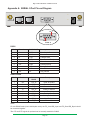
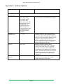
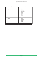
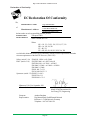
T r a n s P o r t ®W R 2 1 Wireless Routers Installation Guide January 30, 2012 Digi TransPort® WR21 Installation Guide Disclaimer Digi International makes no representations or warranties with respect to the contents or use of this manual, any software drivers or associated application software provided with this product and specifically disclaims any expressed or implied warranties of merchantability or fitness for any particular purpose. Digi International reserves the right to modify or revise all or part of this document, its contents, and any products described herein at any time without prior notification and shall not be responsible for any loss, cost or damage, including consequential damage, caused by reliance on these materials. Digi Technical Support Contact Information United States: (952) 912-3444 or (877) 912-3444 Other Locations: +1 (952) 912-3444 or (877) 912-3444 EMEA +44 870 35 000 35 Safety Notices 1. Please read all instructions before installing and powering the unit. You should keep these instructions in a safe place for future reference. 2. If the power supply shows signs of damage or malfunction, stop using it immediately, turn off the power and disconnect the power supply before contacting your supplier for a repair or replacement. 3. Changes or modifications not expressly approved by the party responsible for compliance could void the user’s authority to operate the equipment. Use only the accessories, attachments, and power supplies provided by the manufacturer – connecting non-approved antennas or power supplies may damage the unit, cause interference or create an electric shock hazard, and will void the warranty. 4. Do not attempt to repair the product. The unit contains no electronic components that can be serviced or replaced by the user. Any attempt to service or repair the unit by the user will void the product warranty. 5. Products in the TransPort WR® family are designed for indoor use (except for the WR44 R) and should be used in an environment that is suitable for computers and other electronic equipment. 6. Ports that are capable of connecting to other apparatus are defined as SELV ports. To ensure conformity with IEC60950 ensure that these ports are only connected to ports of the same type on other apparatus. Page 2 Digi TransPort® WR21 Installation Guide Special notes on safety for wireless routers Digi International products are designed to the highest standards of safety and international standards compliance for the markets in which they are sold. However, cellular-based products contain radio devices which require specific consideration. Please take the time to read and understand the following guidance. Digi International assumes no liability for an end user’s failure to comply with these precautions. Wireless routers incorporate a wireless radio module. Users should ensure that the antenna(s) is (are) positioned at least 1 meter away from themselves and other persons in normal operation. When in a hospital or other health care facility, observe the restrictions on the use of mobile phones. Do not use the unit in areas where guidelines posted in sensitive areas instruct users to switch off mobile phones. Medical equipment may be sensitive to RF energy. The operation of cardiac pacemakers, other implanted medical equipment and hearing aids can be affected by interference from cellular terminals such as the wireless routers when places close to the device. If in doubt about potential danger, contact the physician or the manufacturer of the device to verify that the equipment is properly shielded. Pacemaker patients are advised to keep the wireless router away from the pacemaker while it is on. Wireless routers must NOT be operated on aircraft. The operation of wireless appliances in an aircraft is forbidden to prevent interference with communications systems. Failure to observe these instructions may lead to the suspension or denial of cellular services to the offender, legal action, or both. As with any electrical equipment, do not operate the unit in the presence of flammable gases, fumes or potentially explosive atmospheres. Radio devices should not be used anywhere that blasting operations are taking place. Wireless routers receive and transmit radio frequency energy when power is on. Interference can occur if used close to TV sets, radios, computers or inadequately shielded equipment. Follow any special regulations and always power off your unit wherever forbidden or when it may cause interference or danger. SOS IMPORTANT! - Wireless routers operate using radio signals and cellular networks cannot be guaranteed to connect in all possible conditions. Therefore, never rely solely upon any wireless device for life critical communications. Warning: For environments where the temperature is 55° C or above, this device must be installed in a restricted access area. Page 3 Digi TransPort® WR21 Installation Guide Table of Contents 1 Package Contents ...................................................................................... 5 2Introduction ................................................................................................. 6 2.1 Front Panel Features ........................................................................................7 2.2 Rear Panel Features .........................................................................................8 3Installation ................................................................................................... 9 4 Configuration .............................................................................................. 11 4.1 Network Settings ...............................................................................................11 4.2 Web Interface.....................................................................................................11 4.3 Command Line Interface (CLI)...........................................................................14 5Troubleshooting ......................................................................................... 16 5.1 Troubleshooting Resources ..............................................................................16 5.2 Unable to open the Web Interface ....................................................................16 5.3 Unable to log in to the Web Interface ................................................................16 6 Specifications ............................................................................................. 17 7Accessories ................................................................................................ 18 Appendix A: SERIAL 0 Port Pin-out Diagram....................................... 19 Appendix B: Software Options............................................................... 20 Page 4 Digi TransPort® WR21 Installation Guide 1 Package Contents TransPort WR21 Cellular Antenna(s) Ethernet Cable Installation Guide Power Supply Adapters [Non-US models only] Power Supply (some models may include a DC Power Cord or have no Power Supply) any item is missing or damaged, please contact your supplier. Also, make a record of any damage that may If have occurred during shipping and report it to the carrier. Depending on model and configuration, the package will also contain additional cables/antennas as appropriate. Page 5 Digi TransPort® WR21 Installation Guide Preface This guide describes the installation procedure for the Digi TransPort WR family of routers. It is intended to provide sufficient information to be able to connect the unit to terminal equipment and power-on the unit. A complete reference guide to the software features that are available on the product is available separately in PDF format and can be downloaded from the Digi International web site (www.digi.com). 2 Introduction Digi TransPort WR21 is a full-featured, cellular router offering the flexibility to scale from basic connectivity applications to enterprise class routing and security solutions. With its high performance architecture, Digi TransPort WR21 is designed for Wide Area Network connectivity including 2.5G/3G/4G networks. Digi TransPort WR21 is available with a range of Ethernet, Serial (RS232, RS422/485) and Power connector options. Digi TransPort WR21 also offers an optional advanced routing, security and firewall feature set including stateful inspection firewall and integrated VPN. Enterprise class protocols incorporate BGP, OSPF and VRRP+, a patented technology built upon the popular VRRP failover standard providing true auto sensing, auto failure and auto recovery of any line drop. Page 6 Digi TransPort® WR21 Installation Guide 2.1 Front Panel Features 1. SIM/R-UIM Sockets (SIM card models only) - SIM 1 and SIM 2 are for use with the Subscriber Identification Module(s) (SIMs) or Removable User Identification Module(s) (R-UIMs). 2. LED Status Indicator - POWER - Illuminates steady when power is connected. 3. LED Status Indicator - SERVICE - Illuminates steady when there is a network connection to the WWAN interface and flashes when data is transmitted or received. 4. LED Status Indicator - WWAN (Wireless Network) - Flashes to show which network mode the unit is operating in: • Off - no service • 1 blink - GPRS mode • 2 blinks - EDGE mode • 3 blinks - UMTS mode • 4 blinks - HSDPA mode • 5 blinks - HSUPA mode • On steady - CDMA mode 5. LED Status Indicator - SIGNAL. • 0 LEDs illuminated: < -113 dBm (effectively no signal) • 1 LED illuminated: >= -112 dBm and <= -87 dBm (weak) • 2 LEDs illuminated: >= -86 dBm and <= -71 dBm (medium) • 3 LEDs illuminated: >= -70 dBm and <= -51 dBm (strong) 6. USB Host Connector - The USB host connector may be used to connect compatible USB 2.0 client devices such as memory sticks, and serial adapters. The total current available to power USB devices is 0.5A. 7. Reset button - The reset button allows the user to return the unit to its factory default settings. 2.1.1 Reset instructions Step 1)Turn the unit on and wait 15 seconds for the unit to complete its initialization process. Step 2)Press and hold the reset button gently for 5 seconds. After this time, the unit will automatically re-boot and display a pattern of alternating LEDs flashing followed by the normal boot sequence. Note: Do not remove power from the unit during this operation as corruption of the flash memory may occur. Page 7 Digi TransPort® WR21 Installation Guide 2.2 Rear Panel Features 7 WWAN SECONDARY WWAN PRIMARY LAN 0 LAN 1 SERIAL 0 9-30VDC 2A MAX 1. Secondary Cellular (WWAN) Antenna Connector - This SMA female connector is used to connect the unit’s secondary cellular antenna. It is highly recommended to use the secondary antenna for diversity. In most circumstances, dual antennas will provide improved signal strength thus better performance. 2. LAN 0 - This RJ45 port is used to connect the unit to a 10/100 base-TLAN. The port is auto-sensing for speed and wiring (straight-through or cross-over). 3. LAN 1 (optional) - This RJ45 port is used to connect the unit to a 10/100 base-TLAN. The port is autosensing for speed and wiring (straight-through or cross-over). 4. Serial 0 Port - This DB9 port provides an asynchronous RS232 (RS485 optional) serial port with optional RS422/485 support which may be which may be used to connect the unit to a compatible serial device. This is a DCE serial port and allows CLI access to the device by default; the baud rate is 115200. A pinout diagram is available in Appendix A: SERIAL 0 Port Pin-out Diagram on page 19. 5. Power Cord Input – This socket is used to connect the unit to a power source using either the supplied Power supply or DC power cord. The barrel plug connector can be secured by rotating it by 90o once installed into the Digi TransPort unit. 6. Primary Cellular (WWAN) Antenna Connector - This SMA female connector is used to connect the unit’s primary cellular antenna. 7. Power Cord Input (Terminal Block Variant) – This socket is used to connect the unit to an alternative power source. For wiring details, see Section 3 Installation. Page 8 Digi TransPort® WR21 Installation Guide 3 Installation Mounting Tips The Digi TransPort WR21 should be positioned on a flat, level surface or via a wall-mount, rackmount, or DIN rail mounting brackets (see the Accessories section on page 18 for all options). The unit is designed for indoor use and should be mounted in a location with adequate ventilation. Also, do not expose the unit to extremes of heat or cold, strong magnetic fields, or liquids. Step 1)(SIM card models only) - Install the SIM card(s): SIM card(s) should be inserted into SIM Sockets as illustrated in the above Front View image. For SIM 1, the contacts should be face down. For SIM 2, the contacts should be face up. In both cases, the end of the SIM card with the chamfered corner should be inserted first. The Digi TransPort WR21 also allows for dual network installations where one wireless service can be used as a back-up in the event that the primary service fails. These installations cannot be used to access two networks simultaneously. By default, SIM 1 is used for access to the primary network and SIM 2 is used for the back-up network. Page 9 Digi TransPort® WR21 Installation Guide Step 2)Connect the Cellular (WWAN) Antenna(s): Connect the cellular antenna to the “WWAN PRIMARY” connector (SMA Female) on the unit. If the unit is equipped with a secondary cellular antenna connector (WWAN SECONDARY), it is highly recommended to connect an additional antenna to this connector for diversification. Dual antennas will provide improved signal strength thus better performance. Note: For most applications, the antenna(s) included with the unit will provide suitable reception, but some circumstances/environments may require a higher quality antenna or one mounted in a different location. If this is the case, Digi has many antenna options to chose from -- please contact us or visit www.digi.com. If antennas other than the supplied antenna(s) are used, the separation between the two should be no less than five inches (5”). Step 3)Connect the LAN Cable: Connect one end of the Ethernet cable to the “LAN 0” port on the unit and the other end to a LAN port on a PC. Step 4)Connect the Serial Cable (optional): Connect one end of the serial cable (not included) to the “SERIAL 0” port on the unit and other end to the serial port on a third-party serial terminal device. If you wish to connect the unit to a PC, it is recommended that you purchase Digi’s serial cable (P/N: 76000858). Step 5) Connect the Power Supply: Barrel Plug-Type Variants: Connect the barrel plug end of the power supply to the power connector on the unit, and plug the other end into a wall outlet. Notes: ◦◦ “International” units come with interchangeable Power Supply Adapters which can be used according to regional needs. ◦◦ The barrel plug end of the power supply has a twist-lock connector which can be secured by rotating it 90 degrees once installed into the Digi TransPort unit. Terminal Block Variants: Remove the pluggable connector from the unit and screw-down a proper power source to its terminals. Once complete, reconnect the pluggable connector to the unit. A pin-out diagram is located below. WWAN PRIMARY 9-30VDC 2A MAX Pwr Gnd Step 6)When the unit is powered-up, the POWER indicator will illuminate and the unit will initiate a series of diagnostic self-tests. During this process one or more of the other indicators will flash to show that the unit is busy. When the flashing stops, the unit has completed its self-test diagnostics and is ready to be configured. Page 10 Digi TransPort® WR21 Installation Guide 4 Configuration Once the unit has been installed and powered up, it needs to be configured to communicate with the LAN and WAN. Configuration is performed either using the Command Line Interface (CLI) or the Web Interface. The Web Interface (accessed via a web browser e.g. Firefox, IE, Chrome) is the recommended configuration option for most users. Note: You will not be able to use the unit for remote communication until you have subscribed to a suitable mobile/cellular wireless network service. 4.1 Network Settings The default IP address for the LAN port is 192.168.1.1 with a subnet mask of 255.255.255.0. The unit has a DHCP server enabled by default which can assign an appropriate IP address to your PC if the PC is configured to get an IP address automatically. Alternatively you can manually configure your PC to be on the 192.168.1.x network, for example, with an IP address of 192.168.1.2 and subnet mask of 255.255.255.0. Care should be taken to ensure that the unit does not conflict with other devices that may already be on the network. 4.2 Web Interface Step 1)Connect to the Web Interface: Open a Web browser (e.g. Firefox, IE, Chrome) on your PC and navigate to http://192.168.1.1. If successful, you will be prompted to enter a username and password. The default username is “username”, and the default password is “password”. After you have logged in, it is strongly recommended that you immediately change the default username and password. If you are unable to connect to the Web Interface, please refer to the Troubleshooting section on page 16. Step 2)Configure the Unit: The easiest way to perform the initial configuration of the unit is by using the Quick Start Wizard. This wizard allows you to configure the following items where applicable: • Username and password • LAN IP settings • DHCP Server • Mobile module and connection Page 11 Digi TransPort® WR21 Installation Guide The Quick Start Wizard is located in the Getting Started section on the Home menu. 4.2.1 Cellular: CDMA If your unit is to be used on a CDMA network, the embedded module must be provisioned on the network before it can make a connection. Note: If your unit uses a Gobi module (indicated by a model number of WR21-U5xx-xxx-xx), and you did not select the appropriate CDMA carrier via the Quick Start Wizard, you must run the GOBI Module Carrier Wizard before provisioning can be successfully completed. To provision the CDMA mobile device, navigate to the CDMA Provisioning section by clicking on Network > Mobile > CDMA Provisioning. Page 12 Digi TransPort® WR21 Installation Guide 4.2.1.1 CDMA Provisioning CDMA provisioning is different from GSM since CDMA (in most cases) does not use a SIM card. The CDMA modem provisioning process creates a CDMA data connection to the mobile carrier network. This authenticates the modem and retrieves account information which is written to flash memory on the modem module itself, not the Digi’s configuration file. As the mobile account information is stored on the CDMA module, performing a factory reset on the unit will not remove provisioning information from the CDMA module. Important points: • The modem must be provisioned on the network before it will communicate. • The modem must be in coverage area of the native carrier. It cannot be roaming. • There must be sufficient signal strength available to provision the modem. • Always use MIP Profile 1 for manual provisioning unless specified otherwise by your carrier or Digi Technical Support. 4.2.1.2 Automatic vs. Manual Provisioning There are two types of CDMA provisioning: Automatic and Manual. This varies between carriers and even within carriers. Settings in the Web Interface vary based on carrier plan. Below are examples for Verizon Wireless and Sprint: Verizon Wireless always uses Automatic. This means that no further settings are required in the Web Interface - simply press Start in the Automatic section and leave the fields blank. Sprint has two types of plans, Vision for standard Internet connections and DataLink for private IP plans: 1. Sprint Vision uses Automatic provisioning. There are three fields of information that may need to be populated in the Automatic screen. Check with Sprint for correct values (if required). 2. Sprint DataLink requires Manual provisioning. The required fields in the Web Interface vary based on plan and type of embedded modem. As noted above, always use MIP Profile 1 unless otherwise specified by your carrier or Digi Technical Support. Check with your carrier for information about the type of provisioning required and what, if any, data is required to be entered. For more information on configuring the unit, please refer to the Digi TransPort User Guide which is available at www.digi.com. 4.2.2 Cellular: GSM To configure the Wireless WAN/mobile interface on non-CDMA routers (GPRS/UMTS/HSPA), please refer to the Application Guide “QN02 - Configure the wireless WAN (PPP) interface” which can be found on the Digi Support site (http://www.digi.com/support/). It is also essential to configure a dead link detection mechanism for routers using a Wireless WAN/mobile interface (such as GPRS/HSDPA/CDMA). Please refer to the Application Guide “AN07 - Wireless - Wide Area Network (W-WAN) Problem Detection and Recovery” which can also be found on the Digi Support site (http://www.digi.com/support/). Page 13 Digi TransPort® WR21 Installation Guide 4.3 Command Line Interface (CLI) In order to configure the unit serially, ensure that the unit is connected to a PC (as outlined in Step 4 page 10 of the Installation section). Also, terminal emulation software (such as HyperTerminal) will be required. 4.3.1 CLI Notes • To view the current configuration settings, enter the command CONFIG C SHOW. • To save changes made to the unit, enter the command CONFIG 0 SAVE. • All entered commands will take effect immediately. 4.3.2 Communication Settings Step 1)Configure the following settings for the unit: COM Port: [select the appropriate port; typically COM1] Baud Rate: 115200 Data Bits: 8 Stop Bits: 1 Parity: No Parity Flow Control: None Step 2)Ensure the connection is active by entering the command AT. If the device is functioning properly, it will return the response OK. Step 3)Ensure the COM port is setup correctly by entering the command ATI5. 4.3.3 Network Settings To configure the unit with an IP address as part of an existing network, use the commands below. Note: The DHCP server will still operate unless it is disabled. Command ETH 0 IPADDR XXX.XXX.XXX.XXX ETH 0 MASK XXX.XXX.XXX.XXX Description Sets the Eth 0 IP address Sets the Eth 0 subnet mask As an example, to assign the IP address 192.168.10.254/24, the following commands would be entered: ETH 0 IPADDR 192.168.10.254 ETH 0 MASK 255.255.255.0 Note: When setting the mask to the above 255.255.255.0 value, it will not appear in the output of the CONFIG C SHOW command as it is a default value. Page 14 Digi TransPort® WR21 Installation Guide To stop the DHCP server from serving addresses, use the following command: Command DHCP 0 IPMIN X Description Removes the minimum IP address that will be server via DHCP, disabling the DHCP server As an example, to stop the DHCP sever from DHCP requests, enter the command DHCP 0 IPMIN !. The ! variable is used to remove a value or set it back to its default. To retain the DHCP server, but on a different subnet, the following parameters will need to be configured: Command DHCP 0 IPMIN x.x.x.x DHCP 0 IPRANGE DHCP 0 GATEWAY x.x.x.x DHCP 0 MASK x.x.x.x DHCP 0 DNS Description Minimum IP address to assign, the start of the DHCP pool The number of IP addresses in the DHCP pool The IP gateway address the DHCP clients should use (normally this router’s LAN IP address) The subnet mask DHCP clients should use The DNS server DHCP clients should use For more information on CLI commands, visit http://www.digi.com/support/ and view the various reference manuals available. Page 15 Digi TransPort® WR21 Installation Guide 5 Troubleshooting 5.1 Troubleshooting Resources There are several resources available to you for support of your Digi product or resolving configuration difficulties at Digi’s Support site, http://www.digi.com/support/. Try these troubleshooting steps to eliminate your problem. After working through these steps and your problem is not solved, try the resources listed below. 1. Digi’s Support knowledge base: http://www.digi.com/support/kbase. 2. Digi TransPort support documents: http://ftp1.digi.com/support/documentation/transport/technicalnotes.htm. 3. If the knowledge base or support forums do not have the information you need, fill out an Online Support Request via: http://www.digi.com/support/eservice/login.jsp?p=true. You will need to create a user account if one is not already set up. When submitting a support request, please include a copy of the debug.txt file from the unit’s flash. This will greatly improve the quality of the initial response you receive. Without this file, it is often very difficult for the support team to provide accurate answers to your queries. For instructions on how to download the debug.txt file from the unit, view the online document “QN24 Extracting the debug.txt file from a Digi TransPort or Sarian router”. 5.2 Unable to open the Web Interface Ensure that the LAN cable is properly connected to the LAN port and that the “LAN” status indicator on the front of the unit is illuminated. If it is not, then there is a problem with either the LAN cable or the device it is connecting to. If the status indicator is illuminated, check that the PC can communicate with the unit. To do this, open the Command Prompt window on your PC and enter the command “ping 192.168.1.1”. If you do not get a response, then the problem could be one of the following: • The IP address of the unit has been changed from its default of 192.168.1.1. Use the Digi TransPort Connection Wizard (which can be downloaded from the Support area at Digi.com or the Digi Device Discovery Tool). It can usually discover the unit on a network as long as the unit’s firewall has not been enabled. • PC IP configuration. The PC’s LAN interface that is connected to the unit should be configured to “Obtain an IP address automatically”. If required, the Digi TransPort Connection Wizard can be used to configure the PC. • Check the PC’s LAN connection and any LAN device (e.g. Ethernet switch) that is used to interconnect to the unit. • Refresh the PC’s IP settings by opening a command window and enter “ipconfig /release” then “ipconfig /renew”. • ARP resolution. Clear the PC’s ARP cache with the command “arp –d *”, then retry the ping command. If you do get a response but are unable to view the Web Interface, then there is most likely a problem with your web browser configuration. 5.3 Unable to log in to the Web Interface Access to the unit can be achieved via any of the asynchronous serial ports. Connect your PC to the unit using a “straight through” RS232 serial cable. This will allow you to change the configuration via the Command Line Interface (CLI). Please refer to the Digi TransPort User Guide for information on how to use the CLI. The User Guide can be downloaded from the Digi Support site. If you have further questions about your product please contact Digi Technical Support (see page 2 for contact information). Page 16 Digi TransPort® WR21 Installation Guide 6 Specifications Specifications Digi TransPort WR21 General Features: Dimensions (L x W x H) 3.9” x 5.2” x 1.3” (10 cm x 13.1 cm x 3.2 cm) Weight 0.85 lbs. Other Standard dual SIM (SIM protection cover option) RF Features: GSM Models GPRS GPRS Class 10, Quadband 850/900/1800/1900 MHz EDGE GPRS Class 10/EDGE Class 10, Quadband 850/900/1800/1900 MHz HSDPA/HSUPA/UMTS 850/900/1900/2100 MHz with Rx Diversity CDMA Models CDMA/EV-DO Rev A Dualband 800/1900 MHz with Rx Diversity; optional multi-mode GSM/ EV-DO Gobi support; 450 MHz, 3.1 Mbps down / 1.8 Mbps up, R-UIM support Power Requirements: Power Input 9 - 30 VDC Power Supply 100 - 240 VAC 50/60 Hz with barrel connector, optional barrel connector with bare wire leads Power Consumption 6W @ 12 VDC Environmental: Operating Temperature -20° C to +55° C; -35° C to +75° C with reduced cellular performance Relative Humidity 20% to 95% (non-condensing) Ethernet Isolation 1.5 kV Serial Port Protection (ESD) 1.5 kV Approvals: Mobile Certifications - GSM/ UMTS R&TTE, EN 301 511 Mobile Certifications - CDMA/ EV-DO CDG TIA/EIA-690, CDG TIA/EIA-98-E Wireless Carrier Certifications Certified by most major carriers. See www.digi.com for current listing. Safety UL 60950, CSA 22.2 No. 60950, EN60950 Emissions / Immunity CE, FCC Part 15 Class B, AS/NZS CISPR 22, EN55022 Class A Page 17 Digi TransPort® WR21 Installation Guide 7 Accessories AC Power Supplies North America (NA) 76000823 International (Intl.) 76000823 NA - Extended Temp. 76000752 Intl. - Extended Temp. 76000788 DC Power Cords Barrel Plug to Bare Wire 76000821 Barrel Plug to 12V Auto Power Outlet 76000860 Cables RJ45 to RJ45 - 0.5m 76000825 RJ45 to RJ45 - 2m 76000826 RJ45 to RJ45 Crossover - 2m 76000827 RJ45 to RJ45 - 12’ 76000828 RJ45 to RJ45 Crossover - 12’ 76000829 SMA Male to SMA Female - 5m 76000830 SMA Male to SMA Female - 10m 76000831 SMA Male to SMA Female - 15m 76000832 Antennas - Cellular Direct Mount, Quad Band, 2dBi 76002050 Direct Mount, Penta Band, 2dBi 76002052 Direct Mount, Dual Band, 3dBi DC-ANT-DBDP3 Magnet Mount, Penta Band, 2.5dBi 76002051 Magnet Mount, Dual Band, 4.0dBi DC-ANT-DBHG Glass Mount, Quad Band, 1.5dBi 76000844 Glass Mount, Penta Band, 0dBd 76000845 Surface/Marine Mount, Quad Band, 0dBi - 2.15dBi 76000864 Surface/Through-hole Mount, Quad Band, 0dBd 76000846 Surface/Through-hole Mount, Quad Band, 3.15dBi 76000847 Antenna Mounting Brackets L-shaped wallmount, 16.5mm hole 76000850 L-shaped wallmount, 12mm hole Compatibility: 76000843, 76000841 76000851 L-shaped wallmount, 20mm hole Compatibility: 76000847 76000852 Page 18 Digi TransPort® WR21 Installation Guide Appendix A: SERIAL 0 Port Pin-out Diagram WWAN SECONDARY WWAN PRIMARY LAN 0 SERIAL 0 LAN 1 9-30VDC 2A MAX Pin 1 Pin 9 SERIAL 0 RS232 Pin # Direction RS232 DCE Description 1 Out DCD Data Carrier Detect 2 Out RXD Receive Data 3 In TXD Transmit Data 4 In DTR Data Terminal Ready 5 N/A GND Ground 6 Out DSR Data Set Ready 7 In RTS Ready To Send 8 Out CTS Clear To Send 9 Out RI Ring Indicate RS422/ RS485 Pin # Direction RS422/ RS485 Description 1 Out CTS_B Clear To Send B 2 Out RD_A Receive Data A 3 In TD_A Transmit Data A 4 In RTS_B Ready To Send B 5 N/A GND Ground 6 Out RD_B Receive Data B 7 In RTS_A Ready To Send A 8 Out CTS_A Clear To Send A 9 In TD_B Transmit B Notes: For true RS485 mode (2-wire half-duplex mode), the TD_A and RD_A pair and TD_B and RD_B pair should be connected together. The CTS and RTS signals for optional and not normally needed for RS485. Page 19 Digi TransPort® WR21 Installation Guide Appendix B: Software Options Features Standard Enterprise (includes Standard feature set) Local Programming Python Protocols HTTP, HTTPS, FTP, SFTP, SSL, SMTP, iDigi SNMP, SNMP (v1/v2c/v3), SSH, Telnet and CLI for web management; remote management via software tool (option); SMS management, protocol analyzer, ability to capture PCAP for use with Wireshark; DynDNS Same as Standard plus iDigi; Dynamic DNS client compatible with BIND9/No-IP/DynDNS Security / Firewall / VPN IP Filtering RADIUS TACACS+, SSL, SSLv2, SSLv3, FIPS 197, L2TP, (5 tunnels included); IPSec with IKEv1, IKEv2, ISAKMP; DES, 3DES and AES up to 256-bit encryption; SCEP for X.509 certificates, Open VPN client and server, PPTP; IPSec/PPP/L2TP VPN Server support; Stateful inspection firewall with scripting; Content Filtering (via 3rd party) Routing NAT, NATP Bridging, NAT/NAT-Traversal, NAPT forwarding; PPP, PPPoE, GRE; IP Routing Protocol: PPP, GRE, RIP (v1 & v2) OSPF, SRI, BGP; IP Failover: VRRP, VRRP+TM; VLAN support; STP (Spanning Tree Protocol); DHCP; Automatic failover/failback to second GSM network/Standby APN; Optional IPv6; iGMP routing (multicast); IP pass-through (advanced) Specialty Protocol RealPort RealPort; Modbus UDP/TCP to Serial; Legacy Protocols (X.25 (including X0T), SNA/IP, TPAD and PAD); Protocol switch Page 20 Digi TransPort® WR21 Installation Guide Standard Version Firewall Advanced Version Firewall Actions: • block • pass Actions: • block • pass • pass-ifup • pass-ifupnr • debug • touser • dscp • vdscp Options: • routeto • oosed Options: • onvlan • onvrf • oneroute • routeto • oosed Stateful Inspection: No Stateful Inspection: Yes Page 21 Digi TransPort® WR21 Installation Guide Declaration of Conformity EC Declaration Of Conformity We, Digi International Manufacturer's Name: of 11001 Bren Road East Minnetonka, MN 55343 declare under our sole responsibility that the product: Transport WR21 Product Name: Model Numbers: WR21-NNHH-DFF-XX Manufacturer's Address: Where NN = C0, C3, C8, E1, U4, U5, U6, U7, U8 HH = 1A, 1B, 2A, 2B FF = B1, E1 XX = SD, SF, SL, SN, SU, SW, XA, XB to which this declaration relates are in conformity with the essential requirements and other relevant requirements of the R&TTE Directive (1999/5/EC) Safety: (article 3.1a) EMC: (article 3.1b) EN60950-1:2006 +A11 (2009) EN55022:2006 +A1 (2007) class B EN55024:1998 + A1:2001 + A2:2003 EN61000-3-2:2006 + A1:2009 + A2:2009 EN61000-3-3:2008 EN301 489-7:v1.3.1 EN 301 489-24 V1.5.1 Spectrum: (article 3.2) EN301511:v9.0.2 EN301526:v1.1.1 EN301908-1:v3.2.1 Minnesota, USA 21st, September, 2011 (Place and date of issue) European Representative: Authorised signature for and on behalf of Digi International Inc. Joel Young, VP, Engineering Andreas Burghart Digi International GmbH Branch Breisach Kueferstr. 8, 79206 Breisach, Germany Telephone: +49-7667-908-124 Page 22 mark of autho Digi TransPort® WR21 Installation Guide Product Disposal Instructions The WEEE (Waste Electrical and Electronic Equipment: 2002/96/EC) directive has been introduced to ensure that electrical/ electronic products are recycled using the best available recovery techniques to minimize the impact on the environment. This product contains high quality materials and components which can be recycled. At the end of its life this product MUST NOT be mixed with other commercial waste for disposal. Check with the terms and conditions of your supplier for disposal information. Digi International Ltd WEEE Registration number: WEE/HF1515VU Page 23 Copyright © 2011 Digi International Inc. All rights reserved. Digi, Digi International, the Digi logo, a Digi International Company, the Digi web site, Digi Remote Manager, Digi TransPort, Digi TransPort WR, and Digi TransPort WR21 are trademarks or registered trademarks of Digi International, Inc. in the United States and other countries worldwide. All other trademarks are the property of their respective owners. Information in this document is subject to change without notice and does not represent a commitment on the part of Digi International. Digi provides this document “as is,” without warranty of any kind, either expressed or implied, including, but not limited to, the implied warranties of fitness or merchantability for a particular purpose. Digi may make improvements and/or changes in this manual or in the product(s) and/or the program(s) described in this manual at any time. This product could include technical inaccuracies or typographical errors. Changes are periodically made to the information herein; these changes may be incorporated in new editions of the publication. No part of this document covered by copyright may be reproduced or copied in any form or by any means graphic, electronic, or mechanical, including photocopying, recording, taping, or information and retrieval systems without written permission of Digi International. Digi International 11001 Bren Road East Minnetonka, MN 55343 952-912-3444 or 877-912-3444 (1P):90002024-88 B