1
SV-10
SV-100
Vibro Viscometer
INSTRUCTION MANUAL
1WMPD4000646E
© 2008 A&D Company Ltd. All rights reserved.
No part of this publication may be reproduced, transmitted, transcribed, or translated
into any language in any form by any means without the written permission of A&D
Company Ltd.
The contents of this manual and the specifications of the instrument covered by this
manual are subject to change for improvement without notice.
CONTENTS
1. INTRODUCTION .............................................................................................................................3
1-1 Compliance......................................................................................................................................... 3
1-2 Features ............................................................................................................................................. 5
2. UNPACKING THE VISCOMETER ..................................................................................................6
2-1 Unpacking........................................................................................................................................... 6
2-2 Installing the Viscometer .................................................................................................................... 7
3. DISPLAY AND KEYS ......................................................................................................................8
3-1 Display................................................................................................................................................ 8
3-2 Keys.................................................................................................................................................... 9
3-3 Displaying the Viscosity Values ........................................................................................................ 10
3-3-1 SV-10......................................................................................................................................... 10
3-3-2 SV-100........................................................................................................................................11
4. PRECAUTIONS ............................................................................................................................12
4-1 General Precautions......................................................................................................................... 12
4-2 During Use........................................................................................................................................ 13
4-3 After Use ........................................................................................................................................... 14
4-4 Measuring the Absolute Value of Viscosity....................................................................................... 15
4-4-1 At Measurement ........................................................................................................................ 15
4-4-2 At Calibration ............................................................................................................................. 16
5. MEASUREMENT ..........................................................................................................................17
5-1 Preparing the Sample....................................................................................................................... 17
5-2 Basic Measurement Procedure ........................................................................................................ 19
5-3 Changing Units ................................................................................................................................. 20
6. VISCOSITY CALIBRATION ..........................................................................................................21
6-1 Notes on Viscosity Calibration.......................................................................................................... 21
6-2 Calibration Procedure....................................................................................................................... 22
6-2-1 One-point Calibration................................................................................................................. 23
6-2-2 Two-point Calibration................................................................................................................. 24
6-2-3 Simplified Calibration Using Purified Water (SV-10 only).......................................................... 26
7. FUNCTION SETTING....................................................................................................................28
7-1 Operation.......................................................................................................................................... 28
7-2 Details of the Function Items ............................................................................................................ 30
7-3 Description of Items.......................................................................................................................... 31
7-4 Data Output Format Examples ......................................................................................................... 40
7-4-1 A&D Standard Format................................................................................................................ 40
7-4-2 D.P. Format................................................................................................................................ 42
7-4-3 CSV Format............................................................................................................................... 43
7-4-4 RsVisco Format ......................................................................................................................... 47
1
8. CONNECTION TO A PERSONAL COMPUTER...........................................................................49
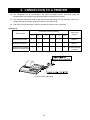
9. CONNECTION TO A PRINTER ....................................................................................................48
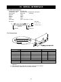
10. RS-232C SERIAL INTERFACE ..................................................................................................51
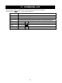
11. COMMAND LIST.........................................................................................................................52
12. TROUBLESHOOTING ................................................................................................................53
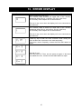
13. ERROR DISPLAY .......................................................................................................................57
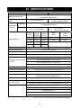
14. SPECIFICATIONS.......................................................................................................................58
15. OPTIONAL ACCESSORIES .......................................................................................................60
16. EXTERNAL DIMENSIONS .........................................................................................................64
Whole View ......................................................................................................................................... 64
Detailed View of the Sensor Unit ........................................................................................................ 64
2
1. INTRODUCTION
This manual describes how the SV series viscometer works and how to get the most out of it in
terms of performance.
Read this manual thoroughly before using the viscometer and keep it at hand for future reference.
1-1 Compliance
Compliance with FCC Rules
Please note that this device generates, uses and can radiate radio frequency energy. This
device has been tested and has been found to comply with the limits of a Class A computing
device pursuant to Subpart J of Part 15 of FCC rules. These rules are designed to provide
reasonable protection against interference when this device is operated in a commercial
environment. If this unit is operated in a residential area, it may cause some interference and
under these circumstances the user would be required to take, at his own expense, whatever
measures are necessary to eliminate the interference.
(FCC = Federal Communications Commission in the U.S.A.)
Compliance with Council Directives
This device features radio interference suppression and safety regulation in
compliance with the following Council Directives
Council directive 89/336/EEC EN61326 EMC directive
Council directive 73/23/EEC EN60950 Safety of Information Technology Equipment
EN61326 Emission and Immunity.
Note
The CE mark is an official mandatory European marking.
Please note that any electronic product must comply with local laws and regulations
when sold or used anywhere outside Europe.
3
4
1-2 Features
High accuracy
The Sine-wave Vibro Viscometer achieves a high measurement accuracy of 1%*1
(repeatability) over the full range.
*1 Refer to "14. SPECIFICATIONS" on page 58.
Wide range continuous measurement
Continuous measurement over the whole measuring range is possible, without replacing the
viscosity detection sensor plates.
Standard temperature sensor
The temperature sensor to measure the sample temperature is installed as standard. The
temperature sensor is located between the two sensor plates. So, the accurate detection of
the relation between temperature and viscosity is possible.
Accurate measurement
Due to the low heat capacity of the viscosity detection unit (sensor plates and temperature
sensor), the time required for temperature equilibrium is short. Thus, the sample viscosity can
be measured accurately in a short time.
Long continuous measurement time
The sensor plates, with a low frequency of 30 Hz and an amplitude of less than 1 mm, apply
very little load to the sample. So, the viscometer can continuously obtain stable viscosity
values without causing a temperature rise or damaging the sample.
Measurement of a non-Newtonian fluid/foaming sample
The thin sensor plates allow little deformation of the sample texture. Thus, non-Newtonian fluid
can be measured in a stable way. And, foaming samples can be measured without breaking
minute foam particles and with less influence scattering large foam particles.
When measuring tap water, bubbles may accumulate on the sensor plates, increasing the
viscosity.
Measurement of a flowing sample
The two sensor plates oscillate in the opposite direction. So, even when a sample is in motion,
errors are eliminated. This allows measurement of a sample while being stirred. The
viscometer can be used for a flowing product line, which enables field management with
identical data used at the laboratories.
Calibration
The viscometer can be calibrated using a standard viscosity fluid or a sample of a known
viscosity. Calibration allows the viscometer to maintain the accuracy constantly.
By calibrating an actual sample, using the viscosity value obtained by another type of
viscometer as a correction value, the measurement data obtained by the SV series viscometer
can be combined into those obtained by the other type of viscometer.
Simplified calibration when measuring the viscosity near 1 mPa⋅s, (SV-10 only)
Simplified calibration using purified water is a one-key operation. The SV-10 has a built-in
function to measure the temperature of the purified water using the temperature sensor and
calculates the viscosity value of the purified water at that temperature.
At this time, be careful not to influence the viscosity value by generating bubbles.
Standard windows communication tools WinCT-Viscosity
Windows communication tools WinCT-Viscosity (CD-ROM) is provided as standard. The
CD-ROM contains the graphing program RsVisco, which imports the data to a personal
computer and displays the results as a graph in real time. With RsVisco, changes in viscosity
over time and temperature dependency of viscosity can be observed easily and the obtained
data can be saved in files.
5
2. UNPACKING THE VISCOMETER
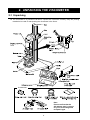
2-1 Unpacking
The viscometer is a precision instrument. Unpack the viscometer carefully. Keep the packing
material to be used for transporting the viscometer in the future.
Accessories
Note
Please confirm that the
AC adapter type is correct
for your local voltage and
receptacle type.
6
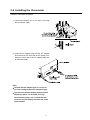
2-2 Installing the Viscometer
Install the viscometer as follows:
1 Connect the display unit to the main unit using
the connection cable.
2 Insert the AC adapter plug into the AC adapter
jack located on the rear side of the display unit.
Insert the other end of the AC adapter plug into
an electrical outlet.
Note:
• Confirm that the adapter type is correct for
the local voltage and power receptacle type.
• The main unit and the display unit have been
adjusted in pairs. For accurate viscosity
measurement, before use, confirm that the
main unit and the display unit have the same
serial number.
7
3. DISPLAY AND KEYS
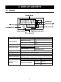
3-1 Display
Name
Description
Displays [- - - - -].
Displays the viscosity value in real
Measurement mode
time.
Freezes the display of the viscosity
Data hold mode
value.
Displays the unit of viscosity.
Displays the temperature value in
Standby mode
real time.
Measurement mode
Freezes the display of the
Data hold mode
temperature value.
Displays the unit of temperature.
Blinks while the measurement is being performed. (While the
sensor plates are in vibrating motion)
Illuminates while the viscometer is in the data hold mode.
Illuminates while measurement is performed using RsVisco, the
graphing program contained in the WinCT-Viscosity (CD-ROM).
Displays " C " in the calibration mode.
At one-point calibration
Blank display [
]
Inputting
Displays [ - - ].
first point
At two-point calibration
Inputting
Displays [ - - ].
second point
Standby mode
Viscosity display
Viscosity units
Temperature display
Temperature units
Processing indicator
Hold indicator
RsVisco link indicator
Calibration indicator
Calibration mode ID
indicator
8
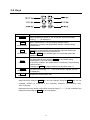
3-2 Keys
Key
ON:OFF
Power
START
Start
measurement
STOP
Stop
measurement
HOLD
Data hold
MODE
Change units
PRINT
Output data
∗1
Description
Turns the power on and off.
When the power is turned on, the viscometer enters the standby
mode ( [- - - - -] is displayed.)
Start a measurement. (The processing indicator blinks.)
Displays the viscosity and temperature values in real time during
measurement.
Stops the measurement (The processing indicator is off) and freezes
the display of the viscosity and temperature values at the time the
STOP key is pressed during measurement.
When the STOP key is pressed again, the viscometer enters the
standby mode.
Freezes temporarily the display of the measurement data (viscosity
and temperature) at the time the HOLD key is pressed during
measurement. (The hold indicator is on.)
In the above condition, the measurement is continued. (The processing
indicator blinks.)
Pressing the HOLD key again releases the data hold mode. ∗1
Changes viscosity units. ∗1
(By the function setting "fnc 1", the measurement elapsed time can
be displayed.)
Outputs the measurement data.
While the measurement is being performed using the graphing program RsVisco, the
data hold mode using the HOLD key and unit changes using the MODE key are not
available. RsVisco is contained in the accessory Windows communication tools,
WinCT-Viscosity.
While data are being output continuously (function setting "prt 2" or SIR command), the
data hold mode using the HOLD key is not available.
9
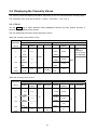
3-3 Displaying the Viscosity Values
The viscosity values are displayed as below, depending on the unit selected and the viscosity range.
The correlation of the units are as follows: 1 mPa⋅s = 0.001 Pa⋅s = 1 cP =0.01 P
3-3-1 SV-10
Use the MODE key to switch between mPa⋅s (Millipascal second) and Pa⋅s (Pascal second), or
between cP (Centipoise) and P (Poise).
The unit selected at the factory before shipment is mPa⋅s.
When the viscosity unit is mPa⋅s or Pa⋅s:
Unit selected
Viscosity
measured
mPa⋅s
1
10
100
1000
10000
Display
0.30
⏐
1.00
|
9.99
10.0
|
99.9
100
|
999
1.00
|
10.00
mPa⋅s
Minimum
Unit
display
Pa⋅s
Remarks
Display
Switches
to Pa⋅s
0.0003
|
0.0010
|
0.0099
0.0100
|
0.0999
0.100
|
0.999
1.00
|
10.00
0.01
mPa⋅s
0.1
1
0.01
Pa⋅s
Minimum
display
Unit
Remarks
Digit
indicating
0.01 mPa⋅s is
not displayed
0.0001
0.0001
Pa⋅s
0.001
0.01
When the viscosity unit is cP or P:
Unit selected
Viscosity
measured
mPa⋅s
1
10
100
1000
10000
Display
0.30
|
1.00
|
9.99
10.0
|
99.9
100
|
999
1 0.0
|
100.0
cP
Minimum
Unit
display
P
Remarks
0.01
cP
0.1
1
0.1
P
Switches
to P
10
Display
0.0030
|
0.0100
|
0.0999
0.100
|
0.999
1.00
|
9.99
10.0
|
100.0
Minimum
display
Unit
0.0001
0.001
0.01
0.1
P
Remarks
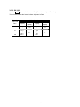
3-3-2 SV-100
Use the MODE key to switch between Pa⋅s (Pascal second) and P (Poise).
The unit selected at the factory before shipment is Pa⋅s.
Viscosity
measured
Pa⋅s
1
10
100
Unit selected
Pa⋅s
Minimum
Display
display
1.00
|
9.99
10.0
|
99.9
100.0
0.01
0.1
P
Minimum
display
Display
10.0
|
99.9
100
|
999
1000
0.1
1
11
4. PRECAUTIONS
To get the optimum performance from the viscometer and acquire accurate measurement data, note
the following:
4-1 General Precautions
Install the viscometer in an environment where the temperature and humidity are not excessive.
The best operating temperature is 25°C±2°C at 45-60% relative humidity.
For precise measurement, install the viscometer where there are no great changes in
temperature and humidity.
Install the viscometer where it is not exposed to direct sunlight and it is not affected by heaters
or air conditioners.
Install the viscometer where it is free of dust.
Install the viscometer away from equipment which produces magnetic fields.
The viscometer uses the Tuning-fork Vibration Method. So, use much care to avoid external
vibration, especially when measuring low viscosity.
Places where the viscometer is prone to vibration are:
Second or higher floor, soft ground, near busy highways or rail lines.
Avoid these places as a measuring site. If measurement is to be performed in such a place, use
an anti-vibration table that is available as an option (AD-1685).
Protect the internal parts from liquid spills and excessive dust.
Do not disassemble the viscometer.
When precise measurement is required, acclimatize the viscometer to the measuring
environment. After installation, plug in the AC adapter and warm up the viscometer for one hour
or more.
12
4-2 During Use
To level the surface of the sample; adjust the leveling feet so that the center of the narrow part
of the right and left sensor plates is on the liquid surface.
The viscosity of a liquid is temperature dependent and changes by negative 2 to negative 10
percent, per degree Celsius. Take changes in the liquid temperature into consideration for an
accurate measurement.
Be sure to calibrate using the standard viscosity fluid or purified water before measurement.
In a measurement that takes a long time, perform calibration periodically, as necessary.
Placing the sensor plates and the temperature sensor in the sample may change the sample
temperature. For precise measurement, leave the sample as is for a while, after placing the
sensor plates and the temperature sensor, to ensure no changes to the sample temperature.
And then, start a measurement.
Ensure a stable power source when using the AC adapter.
Use only your finger to press the keys. Using a sharp instrument such as a pen may damage
keys.
The sample cup is made of polycarbonate (PC) and is not appropriate for organic solvents.
When organic solvents are used as a sample fluid, do not use the accessory sample cup. Use
the glass sample cup (AX-SV-35) that is sold separately or a commercially-available glass
beaker.
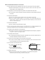
The protector can be raised or removed. So, even when a beaker is used, the viscosity can be
measured with a small amount of sample.
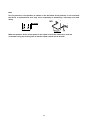
How to remove the protector:
Press the left and right side frames lightly in the
direction indicated as 1 to remove the rotational axis.
Pull the protector in the direction indicated as 2 to
remove.
13
4-3 After Use
Remove any residual sample material from the sensor plates, temperature sensor and
protector using alcohol. Using the sensor plates, temperature sensor and protector with
residue of an old sample left on will cause a measurement error.
Clean the sensor plates carefully to avoid bending them.
The sensor plates and the temperature sensor are made of stainless steel (SUS304). The
surface is plated with 24K gold.
Note
Liquids with strong acidity may remove the gold plating and corrode the sensor plates
and the temperature sensor.
How to clean the sensor plates and temperature sensor
Hold the sensor plate or temperature sensor with
tissue paper. Move the tissue paper downward to
remove the sample.
Then, use tissue paper moistened with alcohol,
to remove any residual sample material.
Clean the sample cup as necessary.
Unlock the cable connector before disconnecting the connection cable.
How to unlock the cable connector
14
4-4 Measuring the Absolute Value of Viscosity
The SV Series Sine-wave Vibro Viscometer, as a measuring principle, detects the product of viscosity
and density.
Displayed viscosity value = Viscosity × Density ⋅ ⋅ ⋅ ⋅ ⋅ [1]
While the displayed value has a unit of mPa⋅s, it indicates the product of viscosity and density.
Example (1) When a sample has an absolute value of viscosity of 2.00 mPa⋅s and density of 1.000:
Displayed value = 2.00 [mPa⋅s] × 1.000
= 2.00 [mPa⋅s]
(2) When a sample has an absolute value of viscosity of 2.00 mPa⋅s and density of 0.800:
Displayed value = 2.00 [mPa⋅s] × 0.800
= 1.60 [mPa⋅s]
Note
The density can be measured, using the density determination kit, AD-1653 in
combination with a balance.
To obtain the absolute viscosity value precisely, do as follows:
4-4-1 At Measurement
Divide the displayed viscosity value by the sample density to obtain the absolute value of viscosity.
Example (1) Measure the sample and confirm the displayed viscosity value.
Here, 736 mPa⋅s as an example.
(2) Check the sample density at the temperature when the sample is measured.
Here, 0.856 as an example.
(3) Divide the displayed viscosity value by the sample density to obtain the absolute value
of viscosity.
Here, 860 mPa⋅s is obtained as the absolute viscosity value.
Absolute value of viscosity =
=
Displayed viscosity value
Sample density
736
0.856
15
≅ 860 mPa⋅s
4-4-2 At Calibration
When calibrating, enter the product of the absolute viscosity value and the density of the standard
viscosity fluid used for calibration, as a correction value.
The standard viscosity fluid has the calculation sheet of kinetic viscosity and viscosity at various
temperatures attached. To obtain the correction value using this sheet, do as follows:
Kinetic viscosity =
Viscosity
Density
From this, Density =
Viscosity
Kinetic viscosity
⋅ ⋅ ⋅ ⋅ ⋅ [2]
Correction value = Viscosity × Density ⋅ ⋅ ⋅ ⋅ ⋅ [3]
When substituting [2] for the density in [3], the following equation is obtained.
Correction value =
Viscosity2
Kinetic viscosity
⋅ ⋅ ⋅ ⋅ ⋅ [4]
Example 1: To calibrate the viscometer using a standard viscosity fluid:
Using the calculation sheet, calculate the value used for calibration.
(1) Check the kinetic viscosity and the viscosity at the temperature when the calibration is
performed.
Here, 1011 mm2/s for the kinetic viscosity and 889 mPa⋅s for the viscosity at 20°C
as an example.
(2) Substitute the values above into equation [4].
8892
1011
≅781
781 mPa⋅s is obtained as a correction value used for calibration.
(3) After calibration, measure the viscosity of the standard viscosity fluid used and confirm
that the viscometer displays the similar value as the correction value, 781 mPa⋅s in
this example. This completes the calibration procedure.
Example 2: To calibrate using a standard viscosity fluid with known values of viscosity and density.
In this example, a standard viscosity fluid with a viscosity of 889 mPa⋅s at 20°C is used.
(1) Check the viscosity value and the density of the standard viscosity fluid at the
temperature when the calibration is performed..
Here, 889 mPa⋅s for the viscosity and 0.878 for the density at 20°C as an example.
(2) Substitute the values above into equation [3].
889 × 0.878 ≅ 781
781 mPa⋅s is obtained as a correction value used for calibration.
(3) After calibration, measure the viscosity of the standard viscosity fluid used and confirm
that the viscometer displays the similar value as the correction value, 781 mPa⋅s in
this example. This completes the calibration procedure.
16
5. MEASUREMENT
5-1 Preparing the Sample
1 Pour the sample into the cup until its surface
reaches between the level gauges. The level
gauges indicate 35 and 45 mL.
2 Attach the cup on the table along the guides.
3 Confirm that the protector is in the position as
shown in the figure.
Raise the lever to release the sensor unit.
4 Pinch the grips, support the front side of the
sensor unit and gently lower the sensor plates
above the sample surface.
5 Lower the lever to secure the sensor unit.
6 Turn the knob on the table so as
to adjust the sample surface to the
center of the narrow part of the
sensor plates. At this time, use the
surface locator plate as a guide.
The surface locator plate has
been secured in position so that
the tip of the surface locator plate
comes into contact with the
sample surface.
SV-10
Note
• Be sure to adjust the sample surface to the
center of the narrow part of the sensor plates.
Otherwise, a measurement error may occur.
• The surface locator plate can be attached or
removed by loosening the screw.
• Before removing the sensor protective
cover, remove the surface locator plate.
• When the surface locator plate was
removed and attached again, it is
recommended
that
calibration
be
performed using the standard viscosity
fluid before measurement.
17
SV-100
Note
Use the protector in the position as shown on the left below. If the protector is not used with
the SV-10, a measurement error may occur, especially in measuring a viscosity over 5000
mPa⋅s.
NO
When the position of the sensor plates in the liquid is not at the same level, level the
viscometer using the leveling feet so that the liquid surface will be leveled.
18
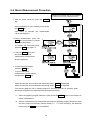
5-2 Basic Measurement Procedure
The below is an example of the SV-10 at shipment.
For the SV-100, the unit at shipment is Pa⋅s
1 With the power turned off, press the ON:OFF
key.
When the display is in the standby mode, press
the START key. *1
After about 15 seconds, the measurement
values are displayed.
2 During measurement, press the
HOLD key as necessary, to freeze
the display temporarily.
To release the data hold mode,
press the HOLD key again. *2
3 Press the STOP key to stop
the measurement. The
measurement results freeze
and are displayed.
4 To stop the measurement,
press the STOP key.
To go on to the next
measurement, set the sample
and press the START key.
When the viscosity value is below the measuring range, Sl TOP is displayed.
When the viscosity value exceeds the measuring range, SH TOP is displayed.
If the sensor plates are not in vibrating motion for about 20 seconds, for example, when
the sample coagulates, the measurement will stop automatically.
∗1
When the graphing program RsVisco is used, press the START button on the RsVisco to
start a measurement.
∗2
While the measurement is being performed using the graphing program RsVisco or data
are being output continuously (function setting "prt 2" or SIR command), the data hold
mode using the HOLD key is not available.
19
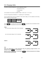
5-3 Changing Units
The units of viscosity available are: mPa⋅s (millipascal second),
Pa⋅s (Pascal second),
cP (Centipoise),
P (Poise).
The correlation of the units are as follows: 1 mPa⋅s = 0.001 Pa⋅s = 1 cP =0.01 P
The units of temperature available are: °C (Celsius) and °F (Fahrenheit).
The unit selected upon power-on depends on the function setting. The unit selected at the factory
before shipment is as shown below.
Model
SV-10
SV-100
Viscosity
mPa・s
Pa・s
Temperature
°C
Use the MODE key to change units. Each time the MODE key is pressed, units are switched as below:
Note that the unit of temperature is fixed in the function setting.
SV-10
In the function setting, mPa⋅s or Pa⋅s is selected:
In the function setting, cP or P is selected:
SV-100
Note
While the measurement is being performed using the graphing program RsVisco, unit
changes using the MODE key is not available.
With the function setting "fnc 1", pressing the MODE key during measurement will display
the measurement elapsed time.
20
6. VISCOSITY CALIBRATION
Viscosity calibration is to correct the viscosity value.
Two calibration methods are available: one-point calibration and two-point calibration, using
standard viscosity fluids.
With the SV-10, simplified calibration using purified water is available.
It is recommended that calibration be performed using a fluid with a known viscosity value
which is close to the sample viscosity.
When the measuring range is great, perform two-point calibration. Two-point calibration
requires two standard viscosity fluids (high viscosity and low viscosity) that are appropriate for
the measuring range.
With the SV-10, when measuring the viscosity near 1 mPa⋅s, simplified calibration using
purified water, which is a one-key operation, is available. The SV-10 has a built-in function to
perform an automatic temperature compensation on the viscosity value, based on the
temperature of the purified water used.
In one-point and two-point calibration, the viscosity of a fluid with a known value, such as a
standard viscosity fluid, is measured, displayed, corrected digitally and saved in memory.
To obtain the absolute viscosity value precisely, use the correction value as described in
"4-4-2 At Calibration".
If the wrong calibration data such as a correction value have been entered, the viscometer
condition can be restored. For details, refer to "Initialization (Clr)" of the function setting.
6-1 Notes on Viscosity Calibration
Pay close attention to the liquid temperature at calibration. Be sure to enter the viscosity
value of the liquid temperature at calibration. Even a standard viscosity fluid has a viscosity
change of -2%/°C to -10%/°C, and purified water, a viscosity change of -2%/°C, when the room
temperature changes.
The temperature of the standard viscosity fluid must be the same as the temperature of the
sensor plates and the temperature sensor. Allow the displayed temperature to stabilize before
calibration.
Be sure to adjust the sample surface to the center of the narrow part of the sensor plates.
Otherwise, a measurement error may occur.
In the calibration mode, the unit of viscosity for the SV-10 is mPa⋅s, for the SV-100, Pa⋅s.
The unit of temperature is fixed to °C.
The viscometer has been calibrated with the protector attached when shipped. Please note
that the value, obtained when the viscometer is calibrated without the protector, may be
different from that upon shipment.
If water other than purified water (such as tap water) is used for simplified calibration, or the
water temperature is different from the ambient temperature, bubbles may accumulate on the
sensor plates and cause a measurement error. Allow the sample to adjust to the ambient
temperature and remove any accumulated bubbles before calibration.
If the measured viscosity of the water is 3.00 mPa⋅s or greater, it is contaminated and
simplified calibration can not be performed using it. Replace the water.
21
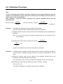
6-2 Calibration Procedure
Note
As to the correction value used for one-point calibration and two-point calibration, enter the
product of the absolute viscosity value and the density of the standard viscosity fluid. For
details, refer to "4-4-2 At Calibration".
After calibration, check the values, comparing the product described above with the
displayed value.
Kinetic viscosity =
Viscosity
From this, Viscosity × Density =
Density
Viscosity2
Kinetic viscosity
is obtained.
Example 1: To calibrate the viscometer using a standard viscosity fluid:
Using the calculation sheet, calculate the value used for calibration.
(1) Check the kinetic viscosity and the viscosity at the temperature when the calibration is
performed.
Here, 1011 mm2/s for the kinetic viscosity and 889 mPa⋅s for the viscosity at 20°C
as an example.
(2) Substitute the values above to obtain the value for
8892
1011
Viscosity2
Kinetic viscosity
.
≅781
781 mPa⋅s is obtained as a correction value used for calibration.
Example 2: To calibrate using a standard viscosity fluid with known values of viscosity and density.
In this example, a standard viscosity fluid with a viscosity of 889 mPa⋅s at 20°C is
used.
(1) Check the viscosity value and the density of the standard viscosity fluid at the
temperature when the calibration is performed..
Here, 889 mPa⋅s for the viscosity and 0.878 for the density at 20°C as an example.
(2) Substitute the values above to obtain the value for Viscosity × Density.
889 × 0.878 ≅ 781
781 mPa⋅s is obtained as a correction value used for calibration.
22
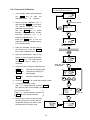
6-2-1 One-point Calibration
1
2
3
4
5
The below is an example of the SV-10.
For the SV-100, the unit is Pa⋅s
In the standby mode, press and hold
the HOLD key to enter the
calibration mode. " Cal " appears.
(Standby mode)
Select one-point calibration (Cal-1)
and press the PRINT key to confirm.
The standby mode of the onecalibration mode appears.
Use the MODE key to switch
between the calibration modes,
one-point calibration (Cal-1) or
two-point calibration (Cal-2).
Press the STOP key to exit the
calibration mode. The display returns
to the standby mode.
Press and hold
(One-point calibration)
(One-point calibration
standby mode)
Place the standard viscosity fluid in
the sample cup. Press the START
key to start a measurement.
Set standard viscosity fluid
After the measurement, wait for the
display to become stable and press
the PRINT key. The measurement
value blinks and is ready to be
corrected.
Correct the value using the following keys:
MODE key
Switches the blinking digits.
START key
Changes the setting of a
blinking digit.
STOP key
Moves the decimal point.
(Measurement mode)
When the data
is stabilized
(Correct the value)
6
Press the PRINT key to confirm the correction value.
7
To exit the calibration mode:
With " end " being displayed, press the PRINT
key again to return to the standby mode.
To correct the value:
With " end " being displayed, press the
STOP key and correct the value.
8
To correct
(End of one-point calibration)
Measure the viscosity of the standard
viscosity fluid used. Confirm that the
viscometer displays the similar value
as the entered correction value.
(Confirm the value)
23
(Standby mode)
The below is an example of the SV-10.
For the SV-100, the unit is Pa⋅s
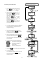
6-2-2 Two-point Calibration
1
In the standby mode, press and hold
the HOLD key to enter the
calibration mode. " Cal " appears.
2
Select two-point calibration (Cal-2)
and press the PRINT key to confirm.
The standby mode of the twocalibration mode appears.
Use the MODE key to switch
between the calibration modes,
one-point calibration (Cal-1) or
two-point calibration (Cal-2).
Press the STOP key to exit the
calibration mode. The display returns
to the standby mode.
3
In two-point calibration mode, the calibration
mode ID indicator (-) appears below the
temperature display.
4
Place the standard viscosity fluid in the
sample cup. Press the START key to start
the measurement of the first point.
5
After the measurement, wait for the display
to become stable and press the PRINT key.
The measurement value blinks and is ready
to be corrected.
6
Correct the value using the following keys:
MODE key
Switches the blinking digits.
START key
Changes the setting of a
blinking digit.
STOP key
Moves the decimal point.
7
Press the PRINT key to confirm the correction value.
8
To correct the value:
In the calibration standby mode to enter the
second point, press the STOP key and
correct the value.
24
9
When the measurement of the first point has
completed, clean the sensor plates,
temperature sensor and protector and
prepare the second standard viscosity fluid.
From the previous page
10 Place the second standard viscosity fluid in
the sample cup. Press the START key to
start the measurement of the second point.
11 After the measurement, wait for the display
to become stable and press the PRINT key.
The measurement value blinks and is ready
to be corrected.
Set standard viscosity fluid
(Second point measurement mode)
When the data
is stabilized
12 Correct the value using the following keys:
MODE key
Switches the blinking digits.
START key
Changes the setting of a
blinking digit.
STOP key
Moves the decimal point.
(Correct the second point value)
13 Press the PRINT key to confirm the
correction value.
14 To exit the calibration mode:
With " end " being displayed, press the PRINT
key again. The calibration data is saved and the
display returns to the standby mode.
To correct
(End of two-point calibration)
To correct the value:
With " end " being displayed, press the
STOP key and correct the value.
(Standby mode)
15 Measure the viscosity of the two standard
viscosity fluids used. Confirm that the
viscometer displays the similar value as the
entered correction value for each fluid.
(Confirm the value
of the first fluid)
25
(Confirm the value
of the second fluid)
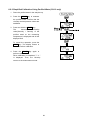
6-2-3 Simplified Calibration Using Purified Water (SV-10 only)
1
Place the purified water in the sample cup.
2
Press the START key to measure
the purified water. Confirm that the
viscosity and temperature values are
stabilized.
3
Press and hold the START key.
The
theoretical
viscosity
value(Viscosity × Density) of the
purified water at the measuring
temperature is displayed and all the
displays blink.
To cancel the operation, press the
STOP key. The display returns to
the status before calibration.
4
Press the START key again to
perform calibration.
When calibration is completed, " end "
is displayed. Then, the viscosity
returns to the measurement mode.
26
Reference data: Theoretical viscosity value (Viscosity × Density)
of the purified water at various temperatures
Temperature (°C)
10.0
11.0
12.0
13.0
14.0
15.0
16.0
17.0
18.0
19.0
20.0
21.0
22.0
23.0
24.0
25.0
26.0
27.0
28.0
29.0
30.0
Viscosity × Density (mPa・s)
1.31
1.27
1.24
1.20
1.17
1.14
1.11
1.08
1.05
1.03
1.00
0.98
0.95
0.93
0.91
0.89
0.87
0.85
0.83
0.81
0.79
27
7. FUNCTION SETTING
The viscometer, by selecting functions to be used in the function setting, can specify the
performance appropriate to the usage.
Each function is assigned parameters. The performance of a function is specified by changing the
parameter.
The parameters saved, even if the power is turned off, are maintained in non-volatile memory.
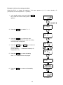
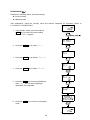
7-1 Operation
The operational procedure of the function setting is as follows:
1
In the standby mode, press and hold the MODE key to enter the function setting mode.
2
Press the MODE key to select a function item.
3
Press the PRINT key to confirm the function item. The changeable digit blinks.
4
Press the START key or HOLD key to change the blinking digit.
5
START key
Increases the value of the blinking digit. When the value reaches the upper
limit of the setting range, the minimum value appears again.
HOLD key
Decreases the value of the blinking digit. When the value reaches the lower
limit of the setting range, the maximum value appears again.
To save the new setting, press the PRINT key. After " end ", the next item is displayed.
To cancel the new setting, press the STOP key. The next item is displayed.
6
To change other settings, repeat the procedure starting at step 2.
7
To exit the function setting mode, press the STOP key. The viscometer returns to the
standby mode.
Note
The operational procedures for setting the date and
time ("Cladj"), ID number ("id") and initialization
("Clr") are not the same as the procedure described
above. Refer to "7-3 Description of Items".
"Date/Time"
pages 31-33
"Device ID Number"
pages 37-38
28
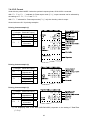
Example of the function setting procedure
Using the SV-10, to change the setting of "Unit upon power-on (Unit)" to the viscosity: cP
(Centipoise) and the temperature: °C (Celsius).
1
In the standby mode, press and hold the MODE
key to enter the function setting mode. " Cladj "
appears.
2
Press the MODE key to select " Unit ".
3
Press the PRINT key to confirm the item.
(The decimal point illuminates when the setting
currently saved is displayed.)
4
Press the START key or HOLD key to select the
unit to be used.
(In this example, " 2 " is selected. Viscosity: cP,
Temperature: °C)
5
Press the PRINT key to save the setting.
After " end ", the next item is displayed.
6
Press the STOP key to return to the standby
mode.
29
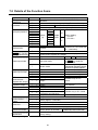
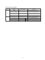
7-2 Details of the Function Items
Function item
Cladj
Date/Time
Cond
Condition
Parameter
pnt
0
1
2
0
1
2
3
4
5
6
7
0
Decimal point
1
fnc
MODE key function
during measurement
prt
0
1
Data output mode
1
Unit
Unit upon power-on
0
•
•
•
•
•
•
2
type
Data output format
5-at
Measurement
elapsed time output
5-td
Date/time output
5-ed
Other output
0
1
2
3
0
1
0
1
0
1
2
pU5e
Pause at data
output
erfnc
Reserved
id
Device ID number
Clr
Initialization
• Factory setting
Description
Sets the order of the date (YMD,MDY,DMY) and the
date/time.
Follows the viscosity changes quickly. (Prone to vibration)
•
•
•
•
3
0
Follows the viscosity changes slowly.
(Stable values)
mPa⋅s
Pa⋅s
°C
cP
Factory setting:
P
Viscos
TemperSV-10=0
-ity
ature
mPa⋅s
SV-100=1
Pa⋅s
°F
cP
P
Dot
With "Comma" selected, the
separator for CSV format will
Comma
be ";" (semicolon).
Switches viscosity units.
Switches between the temperature display and the
measurement elapsed time display.
Key mode
Press the PRINT key to output data.
Outputs automatically when
Auto print mode
the STOP key ends the
measurement.
Continuous output during
Stream mode
measurement. Outputs the viscosity
only when D.P. format is selected.
A&D standard format
For AD-8121B MODES 1&2
D.P. format
For AD-8121B MODE 3
CSV format
For a personal computer
RsVisco format
For graphing program RsVisco
No output
Available only for D.P.
format
Output
Available only for D.P. and
No output
CSV formats
Output
No output
Outputs remarks.
Outputs remarks, Device ID Available only for D.P. format
information and signature.
Outputs ID number.
Available only for CSV format
No pause
1
•
Pause (Approx. 2 seconds)
0
|
7
•
Usually use this parameter.
With "5-ed", the device ID information
is added to the measurement data.
Restores the function settings and calibration data to the
factory setting.
Set the device ID number.
30
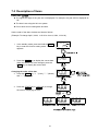
7-3 Description of Items
Date/Time (Cladj)
The upper two digits of the year are not displayed. For example, the year 2003 is displayed as
"03".
The time is set using the 24-hour system.
Do not enter a non-existing date and time.
Set the order of the date, the date and time as follows:
(Example: To change April 5, 2003, 11:22:33 to June 8, 2004, 12:34:00)
1
In the standby mode, press and hold the MODE
key to enter the function setting mode. " Cladj "
appears.
2
Press the PRINT key to display the current date.
When the date is not to be changed, press the
MODE key to display the current time.
Changing the order of the date
3
Press the PRINT key. " y " (Year), " m " (Month)
and " d " (Day) blink.
4
Press the START key or HOLD key to change
the order of displaying the date.
31
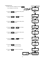
Changing the date
The date is changed in the selected displaying order.
The following is an example when the order of " y " (Year), " m " (Month) and " d " (Day) is selected.
5
Press the MODE key to select the setting value
of " y " (Year). (Example:03)
6
Press the START key or HOLD key to change
the year. (Example:03→04)
START key
Increases the value of the blinking
digit by one.
HOLD key
Decreases the value of the
blinking digit by one.
7
Press the MODE key to select the setting value
of " m " (Month). (Example:04)
8
Press the START key or HOLD key to change
the month. (Example:04→06)
9
Press the MODE key to select the setting value
of " d " (Day). (Example:05)
10 Press the START key or HOLD key to change
the day. (Example:05→08)
11 Press the PRINT key to save the date.
After " end ", the current time is displayed.
32
Changing the time
12 The current time is displayed. Press the MODE
key to display the current date.
13 Press the PRINT key to select the setting value
of the hour. (Example:11)
14 Press the START key or HOLD key to change
the hour. (Example:11→12)
15 Press the MODE key to select the setting value
of the minute. (Example:22)
16 Press the START key or HOLD key to change
the minute. (Example:22→34)
17 Press the MODE key to select the setting value
of the second. (Example:33)
18 Press the START key or HOLD key to change
the second. (Example:33→00)
19 Press the PRINT key to save the time.
After " end ", the next item is displayed.
20 Press the STOP key to return to the standby
mode.
33
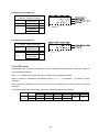
Condition (Cond)
The stability of the viscosity measurement results can be adjusted, taking ambient conditions such
as vibration into consideration.
Parameter
0
1
•
Settings
Description
Follows the viscosity changes When the viscosity value is unstable due to external
quickly.
vibration, set a greater parameter.
(Prone to vibration)
To measure while following the rapid changes in
viscosity, set a smaller parameter.
With a smaller setting, the measurement is prone to
Follows the viscosity changes
external vibration. Consider the ambient conditions
slowly.
of the installation site.
(Stable values)
2
Unit Upon Power-on (Unit)
The units of viscosity and temperature displayed when the power is turned on are specified.
SV-10
Parameter
0
•
1
2
3
Viscosity
4
5
6
7
SV-100
Parameter
1
•
3
Viscosity
5
7
*1
Settings
mPa⋅s
(Millipascal second)
Pa⋅s
°C
(Pascal second)
(Celsius)
cP
(Centipoise)
P
Temper(Poise)
ature
mPa⋅s
(Millipascal second)
Pa⋅s
°F
(Pascal second)
(Fahrenheit)
cP
(Centipoise)
P
(Poise)
Description
In the standby mode, pressing
the MODE key switches the
viscosity unit.
mPa⋅s ⇔ Pa⋅s, cP ⇔ P
With "fnc 0" selected, units can
be switched even during
measurement. *1
Settings
Description
Pa⋅s
In the standby mode, pressing
(Pascal second)
°C
the MODE key switches the
(Celsius)
P
viscosity unit.
(Poise)
TemperPa⋅s ⇔ P
ature
Pa⋅s
With "fnc 0" selected, units can
(Pascal second)
°F
be
switched even during
(Fahrenheit)
P
measurement. *1
(Poise)
While the measurement is being performed using the graphing program RsVisco, unit
changes using the MODE key is not available.
With the SV-10, for a viscosity over 1000 mPa⋅s, the unit is fixed to Pa⋅s, and for a
viscosity over 1000 cP, the unit is fixed to P.
34
Decimal Point (pnt)
Parameter
0
•
1
Settings
Dot
"."
Comma
","
Description
The decimal point format for the displayed measurement data and the
decimal point code for measurement data output via RS-232C are
specified.
With "Comma" selected, the separator for CSV format and RsVisco
format will be ";" (semicolon).
MODE Key Function During Measurement (fnc)
Parameter
0
•
Settings
Switches the viscosity
units.
Description
Each time the MODE key is pressed, the viscosity unit is
switched.
SV-10: mPa⋅s ⇔ Pa⋅s, cP ⇔ P
sv-100: Pa⋅s ⇔ P
Note
With the SV-10, for the viscosity over 1000 mPa⋅s, the
unit is fixed to Pa⋅s and for the viscosity over 1000 cP,
the unit is fixed to P.
Switches between the
temperature display
and the measurement
elapsed time display
1
Each time the MODE key is pressed, the display is switched
between the temperature display and the measurement
elapsed time display.
Upon a measurement start, the temperature display is
selected.
When the elapsed time reaches 100 hours, the display
returns to 0. (99.59.59→00.00.00)
Data Output Mode (prt)
The condition to output the measurement data via RS-232C is set.
Parameter
0
•
Settings
Key mode
1
Auto print mode
2
Stream mode
Description
During measurement or in the data hold mode, pressing the
PRINT key outputs the current measurement values. *2
The measurement values are output automatically when the
STOP key ends the measurement.
Pressing the PRINT key outputs the current measurement
values. *2
The measurement values are output continuously during
measurement.
When D.P. format is selected in "Output format (type)" of the
function setting, only the viscosity value is output, regardless
of the settings of "5-at", "5-td" and "5-ed".
When this mode is selected, the data hold mode using the
HOLD key is not available.
*2
When A&D standard format is selected in "Output format (type)" of the function setting,
pressing the PRINT key in the standby mode will not output the measurement data.
35
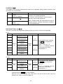
Data Output Format (type)
The output format appropriate for the device connected to RS-232C can be selected.
Parameter
0
•
1
Settings
A&D standard format
D.P. format
Description
Used with the printer MODE 1 or MODE 2 when the optional compact
printer, AD-8121B is connected. Only the viscosity value is output.
Used with the printer MODE 3 when the optional compact
printer, AD-8121B is connected.
With "prt 0" or "prt 1" selected for "Data output mode (prt)",
output contents can be selected by the settings of "5-at",
"5-td" and "5-ed".
CSV format
2
With "prt 2" selected for "Data output mode (prt)", only the
viscosity value is output.
Appropriate when a personal computer is used to collect data.
Measurement values are output in comma separated format.
With "5-td" and "id" settings, the date/time and ID number
can be added to the measurement data.
When a comma is selected as the decimal point by "pnt 1", a
semicolon ";" is used as a data separator.
RsVisco format
3
The viscosity value and the temperature are output using the
internal resolution. *3
Used with the graphing program RsVisco.
When a measurement is started using RsVisco, the viscometer
automatically selects this format.
The viscosity value and the temperature are output using the
internal resolution.*3
The relation between the measuring unit and the internal resolution is as follows:
*3
Model
Internal
resolution
SV-10
SV-100
mPa・s
0.01
-
Viscosity
Pa・s
cP
0.0001
0.01
0.01
-
Temperature
P
0.0001
0.1
°C
°F
0.01
0.01
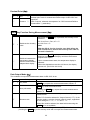
Measurement Elapsed Time Output (5-at)
Parameter
0
1
Settings
No output
•
Output
Description
With D.P. format selected, whether or not to add the
measurement elapsed time (the time elapsed from a
measurement start) to the measurement data can be selected.
For examples of output format, refer to "7-4 Data Output
Format Examples".
36
Date/time Output (5-td)
Parameter
0
1
Settings
Description
With D.P. format or CSV format selected, whether or not to
add the date and time to the measurement data can be
selected.
No output
•
Output
For examples of output format, refer to "7-4 Data Output
Format Examples".
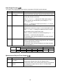
Other Output (5-ed)
Parameter
0
1
2
•
3
Settings
No output
Outputs remarks.
Description
With D.P. format selected, whether or not to add remarks,
Device ID information or signature to the measurement data
can be selected.
Outputs remarks,
Device ID information
and signature.
For examples of output format, refer to "7-4 Data Output
Format Examples".
With CSV format selected, whether or not to add ID number to
the measurement data can be selected.
Outputs ID number.
For examples of output format, refer to "7-4 Data Output
Format Examples".
Pause at Data Output (pU5e)
Parameter
0
1
Settings
Description
Whether or not to take a pause of two seconds each time one
line is output can be selected, when the data are output via
RS-232C.
No pause
•
Pause
(Approx. 2 seconds)
When MODE 3 of the optional compact printer, AD-8121B is
used, select "1".
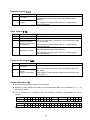
Device ID Number (id)
The ID number is used to identify the viscometer.
Whether or not to add the ID number to the measurement data can be selected by "5-ed" of
the function setting.
The ID number is six characters long. The following characters are available for the ID
number.
Character
Display
Character
Display
0
1
0 1 2 3 4 5 6 7 8 9
(Space)
(Space)
F
P
G
2
H
3
I
4
J
5
K
6
L
7
8
M
N
9
O
Q
-(hyphen)
R
S
T
A
B
C
D
E
a b C d e
U
V
W X
Y
Z
f g H i j k l m N o p q r 5 t U v w x y z
For examples of output format, refer to "7-4 Data Output Format Examples".
37
Setting the ID number
1
In the standby mode, press and hold the
MODE key to enter the function setting
mode. " Cladj " appears.
2
Press the MODE key to select " id ".
3
Press the PRINT key to enter the ID number
setting mode.
4
Set the ID number using the following keys:
5
MODE key
Switches the blinking digits.
START key
Increases the value of the
blinking digit by one.
HOLD key
Decreases the value of the
blinking digit by one.
STOP key
Cancel the operation.
Press the PRINT key to save the setting.
After " end ", the next item is displayed.
6
Press the STOP key to return to the standby
mode.
38
Initialization (Clr)
Restores the following data to the default setting.
Function setting
Calibration data
After initialization, check the viscosity value and perform calibration as necessary. (Refer to
6. VISCOSITY CALIBRATION").
1
In the standby mode, press and hold the
MODE key to enter the function setting
mode. " Cladj " appears.
2
Press the MODE key to select " Clr ".
3
Press the PRINT key to display " Clr no ".
4
Press the START key to select " Clr go ".
5
Press the PRINT key to execute initialization.
After " end ", the next item is displayed.
Initialization has completed.
6
Press the STOP key to return to the standby
mode.
39
7-4 Data Output Format Examples
7-4-1 A&D Standard Format
Used with the printer MODE 1 or MODE 2 when the optional compact printer, AD-8121B is
connected. Only the viscosity value is output.
SV-10 output format example
Viscosity
unit
Display
Remarks
LLLLL mPa・s
OL,-99999999mPs
0.30mPa・s
ST,+00000.30mPs
10.0 mPa・s
ST,+00010.00mPs
The digit of 0.01mPa⋅s is always zero.
ST,+00100.00mPs
The digits of 0.01mPa⋅s and
0.1mPa⋅s are always zero.
1.00 Pa・s
ST,+01000.00mPs
For 1000mPa⋅s or greater, the
displayed unit is Pa⋅s, but the
output unit remains mPa⋅s.
The digits of 0.01mPa⋅s, 0.1mPa⋅s
and 1mPa⋅s are always zero.
H
Pa・s
OL,+99999999mPs
Above measuring range error
L
Pa・s
OL,-99999999Pas
Below measuring range error
0.0003 Pa・s
ST,+000.0003Pas
0.0100 Pa・s
ST,+000.0100Pas
0.100
Pa・s
ST,+000.1000Pas
The digit of 0.0001Pa⋅s is always
zero.
1.00 Pa・s
ST,+001.0000Pas
The digits of 0.0001Pa⋅s and
0.001Pa⋅s are always zero.
H
Pa・s
OL,+99999999Pas
Above measuring range error
L
cP
OL,-99999999 cP
Below measuring range error
0.30 cP
ST,+00000.30 cP
mPa・s
10.0
cP
ST,+00010.00 cP
The digit of 0.01cP is always zero.
cP
ST,+00100.00 cP
The digits of 0.01cP and 0.1cP are
always zero.
P
ST,+01000.00 cP
For 1000 cP or greater, the displayed
unit is P, but the output unit remains cP.
The digits of 0.01cP, 0.1cP and
1cP are always zero.
H
P
OL,+99999999 cP
Above measuring range error
L
0.0030
0.100
P
P
P
OL,-99999999
ST,+000.0030
ST,+000.1000
P
P
P
Below measuring range error
1.00
P
ST,+001.0000
P
P
ST,+010.0000
P
P
OL,+99999999
P
100
cP
10.0
P
Below measuring range error
mPa・s
100
Pa・s
Output format
10.0
H
The digit of 0.0001P is always
zero.
The digits of 0.0001P and 0.001P
are always zero.
The digits of 0.0001P, 0.001P and
0.01P are always zero.
Above measuring range error
: Space (ASC 20h)
40
SV-100 output format example
Viscosity
unit
Display
L
Pa ・
Below measuring range error
ST,+00001.00Pas
s
10.0
H
L
P
Remarks
OL,-99999999Pas
Pa・s
1.00
Pa・s
Output format
Pa・s
ST,+00010.00Pas
Pa・s
OL,+99999999Pas
P
10.0 P
100
P
H
P
OL,-99999999
ST,+000010.0
ST,+000100.0
OL,+99999999
P
P
P
P
The digit of 0.01Pa⋅s is always
zero.
Above measuring range error
Below measuring range error
The digit of 0.1P is always zero.
Above measuring range error
: Space (ASC 20h)
41
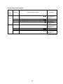
7-4-2 D.P. Format
Used with the printer MODE 3 when the optional compact printer, AD-8121B is connected.
With "prt 0" or "prt 1" selected for "Data output mode (prt)", output contents can be selected by
the settings of "5-at", "5-td" and "5-ed".
With "prt 2" selected for "Data output mode (prt)", only the viscosity value is output
Shown below are SV-10 printing examples.
Printing format example (1)
Function setting
(√=Output Blank=No output)
Measurement
5-at
1
√
elapsed time
Date/time
5-td
1
√
Remarks
√
Device ID
5-ed
2
information
√
Signature
Printing format example (2)
Function setting
(√=Output Blank=No output)
Measurement
5-at
1
√
elapsed time
Date/time
5-td
1
√
Remarks
√
Device ID
5-ed
1
information
Signature
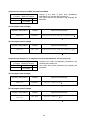
Printing format example (3)
Function setting
(√=Output Blank=No output)
Measurement
5-at
1
√
elapsed time
Date/time
5-td
1
√
Remarks
Device ID
5-ed
0
information
Signature
(*) The displaying order of the date (YMD/DMY/MDY) depends on the setting of "Date/Time
(Cladj)".
42
Printing format example (4)
Function setting
(√=Output Blank=No output)
Measurement
5-at
1
√
elapsed time
Date/time
5-td
0
Remarks
Device ID
5-ed
0
information
Signature
Printing format example (5)
Function setting
(√=Output Blank=No output)
Measurement
5-at
0
elapsed time
Date/time
5-td
0
Remarks
Device ID
5-ed
0
information
Signature
7-4-3 CSV Format
Appropriate when a personal computer is used to collect data. Measurement values are output in
comma separated format.
With "5-td" setting, the date and time can be added to the measurement data.
When a comma is selected as the decimal point by "pnt 1", a semicolon ";" is used as a data
separator.
With CSV format selected, the viscosity value and the temperature are output using the internal
resolution.
The relation between the measuring unit and the internal resolution is as follows:
Model
Internal
resolution
SV-10
SV-100
mPa・s
0.01
-
Viscosity
Pa・s
cP
0.0001
0.01
0.01
-
43
Temperature
P
0.0001
0.1
°C
°F
0.01
0.01
Output format example (1) With ID number, date and time added
Function setting
(√=Output Blank=No output)
Date/time
5-td
1
√
Device
5-ed
3
√
ID number
Outputs in the order of ID number, date, time,
temperature, temperature unit, viscosity and viscosity
unit.
The output data are 52 characters long excluding the
terminator.
SV-10 output format example
Viscosity
/
Temperature
mPa・s
/
°C
Pa・s
/
°F
cP
/
Display
Output format example
Remarks
LLLLLmPa・s
LAB-12,2003/03/19,12:34:56,+025.67,C,+00000.00,mPa s
Zeroes are output for
below measuring
range error.
0.30mPa・s
10.0 mPa・s
100 mPa・s
1.00 Pa・s
LAB-12,2003/03/19,12:34:56,+025.67,C,+00000.30,mPa
LAB-12,2003/03/19,12:34:56,+025.67,C,+00010.00,mPa
LAB-12,2003/03/19,12:34:56,+025.67,C,+00100.00,mPa
LAB-12,2003/03/19,12:34:56,+025.67,C,+01000.00,mPa
H
Pa・s
LAB-12,2003/03/19,12:34:56,+025.67,C,+12000.00,mPa s
L
Pa・s
LAB-12,2003/03/19,12:34:56,+051.23,F,+000.0000, Pa s
0.0003 Pa・s
LAB-12,2003/03/19,12:34:56,+051.23,F,+000.0003, Pa s
0.0100 Pa・s
LAB-12,2003/03/19,12:34:56,+051.23,F,+000.0100, Pa s
0.100
Pa・s
LAB-12,2003/03/19,12:34:56,+051.23,F,+000.1000, Pa s
1.00 Pa・s
LAB-12,2003/03/19,12:34:56,+051.23,F,+001.0000, Pa s
H
Pa・s
LAB-12,2003/03/19,12:34:56,+051.23,F,+012.0000, Pa s
L
cP
LAB-12,2003/03/19,12:34:56,+025.67,C,+000.0000, cP
0.30 cP
LAB-12,2003/03/19,12:34:56,+025.67,C,+00000.30, cP
cP
LAB-12,2003/03/19,12:34:56,+025.67,C,+00010.00, cP
cP
LAB-12,2003/03/19,12:34:56,+025.67,C,+00100.00, cP
P
LAB-12,2003/03/19,12:34:56,+025.67,C,+01000.00, cP
H
P
LAB-12,2003/03/19,12:34:56,+025.67,C,+12000.00, cP
L
P
LAB-12,2003/03/19,12:34:56,+051.23,F,+000.0000,
P
0.0030
P
LAB-12,2003/03/19,12:34:56,+051.23,F,+000.0030,
P
0.100
P
LAB-12,2003/03/19,12:34:56,+051.23,F,+000.1000,
P
1.00
P
LAB-12,2003/03/19,12:34:56,+051.23,F,+001.0000,
P
P
LAB-12,2003/03/19,12:34:56,+051.23,F,+010.0000,
P
P
LAB-12,2003/03/19,12:34:56,+051.23,F,+120.0000,
P
10.0
100
10.0
°C
P
/
°F
10.0
H
s
s
s
s
For 1000 mPa⋅s or
greater, the displayed
unit is Pa⋅s, but the output
unit remains mPa⋅s.
12000 is output for
above measuring
range error.
Zeroes are output for
below measuring
range error.
12 is output for above
measuring range error.
Zeroes are output for
below measuring
range error.
For 1000 cP or greater,
the displayed unit is
P, but the output unit
remains cP.
12000 is output for
above measuring
range error.
Zeroes are output for
below measuring
range error.
120 is output for above
measuring range error.
: Space (ASC 20h)
44
SV-100 output format example
Viscosity
/
Temperature
Display
Output format example
Remarks
Pa・s
LAB-12,2003/03/19,12:34:56,+025.67,C,+00000.00, Pa s
Zeroes are output for
below measuring
range error.
1.00 Pa・s
LAB-12,2003/03/19,12:34:56,+025.67,C,+00001.00, Pa s
L
Pa・s
/
°C
P
/
°F
Pa・s
LAB-12,2003/03/19,12:34:56,+025.67,C,+00010.00, Pa s
H
Pa・s
LAB-12,2003/03/19,12:34:56,+025.67,C,+00120.00, Pa s
L
P
LAB-12,2003/03/19,12:34:56,+051.23,F,+000000.0,
P
10.0
10.0
100
H
P
LAB-12,2003/03/19,12:34:56,+051.23,F,+000010.0,
P
P
LAB-12,2003/03/19,12:34:56,+051.23,F,+000100.0,
P
P
LAB-12,2003/03/19,12:34:56,+051.23,F,+001200.0,
P
120 is output for
above measuring
range error.
Zeroes are output for
below measuring
range error.
1200 is output for
above measuring
range error.
: Space (ASC 20h)
45
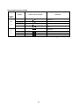
Output format example (2) With date and time added
Outputs in the order of date, time, temperature,
temperature unit, viscosity and viscosity unit.
The output data are 46 characters long excluding the
terminator.
Function setting
(√=Output Blank=No output)
Date/time
5-td
1
√
Device
5-ed
0
ID number
SV-10 output format example
Viscosity / Temperature
mPa⋅s / °C
Display
1.23 mPa⋅s
Output format example
,2003/03/19,12:34:56,+025.67,C,+00001.23,mPa s
: Space (ASC 20h)
SV-100 output format example
Viscosity / Temperature
Pa⋅s / °C
Display
1.23
Pa⋅s
Output format example
,2003/03/19,12:34:56,+025.67,C,+00001.23, Pa s
: Space (ASC 20h)
Output format example (3) To output the measured temperature and viscosity only
Function setting
(√=Output Blank=No output)
Date/time
5-td
0
Device
5-ed
0
ID number
Outputs in the order of temperature, temperature unit,
viscosity and viscosity unit.
The output data are 28 characters long excluding the
terminator.
SV-10 output format example
Viscosity / Temperature
mPa⋅s / °C
Display
1.23 mPa⋅s
Output format example
,,,+025.67,C,+00001.23,mPa s
: Space (ASC 20h)
SV-100 output format example
Viscosity / Temperature
Pa⋅s / °C
Display
1.23 Pa⋅s
Output format example
,,,+025.67,C,+00001.23, Pa s
: Space (ASC 20h)
46
7-4-4 RsVisco Format
Used with the graphing program RsVisco. Measurement data are output in comma separated format.
When a comma is selected as the decimal point by "pnt 1", a semicolon ";" is used as a data separator.
When a measurement is started using RsVisco, the viscometer automatically selects this format.
Measurement data are output in the order of viscosity, viscosity unit, temperature and temperature
unit.
The output data are 25 characters long excluding the terminator
With RsVisco format selected, the viscosity value and the temperature are output using the internal resolution.
The relation between the measuring unit and the internal resolution is as follows:
Model
Internal
resolution
Viscosity
Pa・s
cP
0.0001
0.01
0.01
-
mPa・s
0.01
-
SV-10
SV-100
Temperature
P
0.0001
0.1
°C
°F
0.01
0.01
SV-10 output format example
Viscosity
/
Temperature
mPa・s
/
°C
Pa・s
/
°F
cP
/
°C
P
/
°F
Display
Output format example
LLLLL mPa・s
+00000.00,mPa s,+025.67,C
0.30 mPa・s
+00000.30,mPa s,+025.67,C
10.0 mPa・s
+00010.00,mPa s,+025.67,C
mPa・s
+00100.00,mPa s,+025.67,C
1.00 Pa・s
+01000.00,mPa s,+025.67,C
H
Pa・s
+12000.00,mPa s,+025.67,C
L
Pa・s
+000.0000, Pa s,+051.23,F
0.0003 Pa・s
+000.0003, Pa s,+051.23,F
0.0100 Pa・s
+000.0100, Pa s,+051.23,F
0.100
Pa・s
+000.1000, Pa s,+051.23,F
1.00 Pa・s
+001.0000, Pa s,+051.23,F
100
Remarks
Zeroes are output for below measuring
range error.
For 1000 mPa⋅s or greater, the displayed unit
is Pa⋅s, but the output unit remains mPa⋅s.
12000 is output for above measuring
range error.
Zeroes are output for below measuring
range error.
H
Pa・s
+012.0000, Pa
,+051.23,F
12 is output for above measuring range error.
L
cP
+000.0000, cP
,+025.67,C
Zeroes are output for below measuring
range error.
0.30 cP
+00000.30, cP
,+025.67,C
cP
+00010.00, cP
,+025.67,C
cP
+00100.00, cP
,+025.67,C
P
+01000.00, cP
,+025.67,C
H
P
+12000.00, cP
,+025.67,C
L
P
+000.0000,
P
,+051.23,F
0.0030
0.100
1.00
10.0
H
P
P
P
P
P
+000.0030,
+000.1000,
+001.0000,
+010.0000,
+120.0000,
P
P
P
P
P
,+051.23,F
,+051.23,F
,+051.23,F
,+051.23,F
,+051.23,F
10.0
100
10.0
For 1000 cP or greater, the displayed
unit is P, but the output unit remains cP.
12000 is output for above measuring
range error.
Zeroes are output for below measuring
range error.
120 is output for above measuring range error.
: Space (ASC 20h)
47
SV-100 output format example
Viscosity
/
Temperature
Display
Pa・s
+0000.000, Pa s,+025.67,C
1.00 Pa・s
+00001.00, Pa s,+025.67,C
L
Pa・s
/
°C
Pa・s
+00010.00, Pa s,+025.67,C
Pa・s
+00120.00, Pa
,+025.67,C
P
+000000.0,
P
,+051.23,F
10.0 P
100 P
H
P
+000010.0,
+000100.0,
+001200.0,
P
P
P
,+051.23,F
,+051.23,F
,+051.23,F
10.0
H
L
P
/
°F
Output format example
Remarks
Zeroes are output for below measuring
range error.
120 is output for above measuring range
error.
Zeroes are output for below measuring
range error.
1200 is output for above measuring range error.
: Space (ASC 20h)
48
8. CONNECTION TO A PERSONAL COMPUTER
Using the standard RS-232C serial interface and the RS-232C cable provided, the viscometer can
be connected to a personal computer.
In addition, using the graphing program RsVisco, contained in the accessory Windows
communication tools WinCT-Viscosity, measurement data are imported to a Windows-based
personal computer to display a graph in real time.
For details, refer to "\English\ReadMe.txt" on the CR-ROM.
49
9. CONNECTION TO A PRINTER
The viscometer can be connected to the optional compact printer, AD-8121B using the
standard RS-232C interface and the measurement results can be printed.
The statistical calculation data of the results and the changes in the viscosity value per a
certain time can be printed using the function of the AD-8121B.
Use the AD-8121B accessory cable to connect the printer to the viscometer.
Setting List
Viscometer function settings
What to print
AD-8121B
settings
prt
type
5-at
5-td
5-ed
pU5e
Measurement results
0、1
1
0、1
0、1
0、1、2
1
MODE 3
Statistical calculation
0、1
0
⎯
⎯
⎯
⎯
MODE 1
2
0
⎯
⎯
⎯
0
MODE 2
(Interval printing
is used.)
Changes in the viscosity
value per a certain time
⎯:: Not applicable.
Compact printer, AD-8121B
50
10. SERIAL INTERFACE
RS-232C Serial Interface
Transmission system
Transmission form
Data format
Data bits
Parity
Stop bit
Code
Terminator
EIA RS-232C
Asynchronous, bi-directional, half duplex
Baud rate
2400 bps
7 bits
EVEN
1 bit
ASCII
CR LF (CR: 0Dh, LF: 0Ah)
RS-232C
Bit format
-5 V to -15 V
+5 V to +15 V
Data bits
Start bit
Stop bit
Parity bit
Pin Connections
SV-10/SV-100 (DCE)
Computer (DTE)
Pin No.
Signal Name *1
Description
Direction
Signal Name
1
FG
Frame ground
FG
2
RXD
Receive data
TXD
←
3
TXD
Transmit data
RXD
→
4
RTS
Ready to send *2
RTS
←
5
CTS
Clear to send
*2
CTS
→
6
DSR
Data set ready
DSR
→
7
SG
Signal ground
SG
16, 18, 19, 21, 23
Internal use
Do not connect *3
Others
Not used
*1: Signal names of the viscometer side are the same as the DTE side with TXD and RXD
reversed.
*2: RTS and CTS flow control are not used. CTS output is HI always.
*3: Normal DOS/V cables do not use these terminals.
51
11. COMMAND LIST
The viscometer can be controlled by the following commands from the computer.
( 0Dh、0Ah ) to each command.
Add a terminator
Command
Description
Q
Outputs the current data.
SIR
Outputs data continuously
C
Stops data output by SIR command.
QM
Outputs the data during measurement. (Effective only during measurement.)
START
Same as the START key
STOP
Same as the STOP key
HOLD
Same as the HOLD key
MODE
Same as the MODE key
PRINT
Same as the PRINT key
52
12. TROUBLESHOOTING
The viscometer is a precision instrument. When the measuring environment or the measurement
method is inadequate, correct values can not be obtained. If measurement values do not become
stable or they seem to be incorrect, check as described below. If improper performance persists after
checking, contact the local A&D dealer for repair.
When measurement values do not become stable:
Is the ambient environment free from vibration and drafts?
Places such as second or higher floor or near busy highways or rail lines are prone to
vibration.
Avoid these places or use an anti-vibration table, AD-1685.
Reconsider the setting of "Condition (Cond) ” of the function setting.
Set it to "Cond 2".
Avoid direct drafts in the vicinity of the viscometer.
Is there a strong electrical or magnetic noise source such as a motor near the viscometer?
Install the viscometer away from the electrical or magnetic noise sources.
Is the protector or the sensor protective cover in contact with the sensor plates or the
temperature sensor?
Attach the protector and the sensor protective cover properly so that they do not touch
the sensor plates or the temperature sensor.
Remove the protector, the surface locator plate or the sensor protective cover when
necessary.
How to remove the protector
Press the left and right side frames lightly in the direction indicated as 1 to remove the
rotational axis. Pull the protector in the direction indicated as 2 to remove.
53
How to remove and attach the surface locator plate
Removing
Loosen the screw and remove the surface
locator plate from the temperature sensor.
Attaching
Install the surface locator plate as
shown in the illustration. Slip the locator
plate onto the temperature sensor.
Move the plate to the top of the sensor.
Adjust the position of the locator
plate so that the tip of the locator
plate aligns to the center of the
narrow part of the sensor plates.
Tighten the screw.
Note
When the sensor plate and the surface locator plate are too close, a measurement
error may occur due to the liquid surface tension. Therefore, secure a clearance of
at least 1 mm between the sensor plate and the surface locator plate. Maintain the
clearance by rotating the surface locator plate when necessary.
How to remove the sensor protective cover
(Sensor unit side view)
Remove the protector and the surface locator plate.
Pull the sensor protective cover in the direction indicated as 1 to release the portions A
(two) and B from the protector frame.
Pull the sensor protective cover in the direction indicated as 2 to remove.
Note
When removing the sensor protective cover, it may touch the sensor plates and the
temperature sensor. Use much care not to damage them.
54
When measurement values are not correct:
Has the sample surface been adjusted to the center of the narrow part of the sensor plates?
Adjust the table height by turning the knob so that the center of the narrow part of the
sensor plates is on the sample surface.
Are the positions of the left and right sensor plates in the sample surface the same?
If not the same, level the viscometer using the leveling feet so that the liquid surface will
be leveled.
Are the sensor plates clean?
Remove any residual sample material from the sensor plates using alcohol.
When any residual sample material is on the portion of the sensor plates above the
sample surface, changes in the mass cause the vibration frequency to shift, which will
result in a measurement error.
Are the sensor plates bent?
If bent, contact the local A&D dealer for repair.
Does the sample generate bubbles because of the differences in the sample temperature and
the ambient temperature and do the bubbles accumulate on the sensor plates?
The sample viscosity depends on the temperature.
Generally, the viscosity of a liquid is temperature dependent and changes by negative 2
to negative 10 percent, per degree Celsius.
Is the sample surface lowered?
In a measurement that takes a long time, evaporation may cause the sample surface to
be lowered. Maintain the sample surface level.
Do the main unit and the display unit have the same serial number?
The main unit and the display unit have been adjusted in pairs. Confirm that the main
unit and the display unit have the same serial number.
Is the viscometer in the data hold mode?
To release the data hold mode,
press the HOLD key.
The processing indicator blinks
while a measurement is performed.
Is calibration performed?
When the absolute viscosity value is important, it is recommend that a periodic
calibration be performed using a standard viscosity fluid.
55
When more precise measurement is required:
When the viscometer is installed for the first time or is moved to another location, plug in the
AC adapter and warm up the viscometer for one hour or more, to acclimatize the viscometer to
the measuring environment.
And before measurement, calibrate the viscometer using the sample cup that will be used for
measurement.
Placing the sensor plates and the temperature sensor in the sample may change the sample
temperature. For precise measurement, leave the sample as is for a while, after placing the
sensor plates and the temperature sensor, to ensure no changes to the sample temperature.
And then, start a measurement.
When the sensor plates and the temperature sensor are cleaned using alcohol, the plates and
the sensor are cooled temporarily and their temperature is lowered. Allow the plates and the
sensor to acclimatize to the measuring environment before measurement.
When the temperature values are not correct:
Is the display unit connected to the main unit properly using the connection cable?
Refer to "2-2 Installing the Viscometer" on page 7 to make a connection between the
display unit and the main unit.
When water viscosity is to be measured:
When tap water is poured into the sample cup directly and is measured, bubbles are
generated on the sensor plates due to the difference in pressure and temperature and the
viscosity may increase gradually. Pressurized tap water generates bubbles easily. Therefore,
use distilled or purified water that is not pressurized.
In a measurement that takes a long time, the sample viscosity may increase due to water
contamination. Perform a periodic check on water quality.
56
13. ERROR DISPLAY
Error display
Description
Above measuring range error
The viscosity value exceeds the upper limit of the viscosity
measuring range (SV-10: 11.99 Pa⋅s, SV-100: 119.9 Pa⋅s).
The viscosity of the sample can not be measured.
This error may occur when the display unit is not connected to
the main unit.
Below measuring range error
The viscosity value is below the lower limit of the viscosity
measuring range (SV-10: 0.30 mPa⋅s, SV-100: 0.90 Pa⋅s)
The viscosity of the sample can not be measured.
This error may occur when the display unit is not connected to
the main unit.
The power supply for the internal clock is depleted.
Press any key to enter the clock correction mode. Setting the
clock enables the viscometer to be used temporarily.
If the error occurs frequently, contact the local A&D dealer for
repair.
Internal IC error
Turn the power off. Then, turn the power on again. If this does
not release the error, contact the local A&D dealer for repair.
57
14. SPECIFICATIONS
Measurement method
Measurement method
Viscosity measuring
range
Measurement
accuracy *1
SV-10
SV-100
Sine-wave Vibro Viscometer using the Tuning-fork Vibration method
Vibration frequency 30 Hz
Repeatability
*2
Accuracy *3
1% (Standard deviation)
±3% (1 to 1000 mPa⋅s)
Range
(mPa⋅s)
Minimum display
Unit (Viscosity)
0.3-10
±5%
Minimum Minimum
display
display
(mPa⋅s)
(Pa⋅s)
0.01
0.0001
10-100
0.1
0.0001
100-1000
1
0.001
1000-10000
10
*4
(1 to 10 Pa⋅s)
(1000 to 10000 mPa⋅s)
1-10
Minimum
display
(Pa⋅s)
0.01
10-100
0.1
Range
(Pa⋅s)
0.01
mPa⋅s, Pa⋅s, cP, P
Operating temperature
Pa⋅s, P
10 to 40°C (50 to 104°F)
Minimum sample amount
Temperature display
1 to 100 Pa⋅s
(1000 to 100000 mPa⋅s)
0.3 to 10000 mPa⋅s
35 mL
0 to 160°C/0.1°C, (32 to 320°F/0.1°F) *5
0 to 20°C/32 to 68°F: ±1°C/±1.8°F
Temperature measurement
accuracy
20 to 30°C/68 to 86°F: ±0.5°C/±0.9°F
30 to 100°C/86 to 212°F: ±2°C/±3.6°F
100 to 160°C/212 to 320°F: ±4°C/±7.2°F
Display
Connection cable length
Vacuum fluorescent display (VFD)
1.5 m (between the main unit and the display unit)
Communication
Power supply
Power consumption
External
dimensions/mass
RS-232C standard
AC adapter (Confirm that the adapter type is correct for the local
voltage and power receptacle type.)
Approx. 14 VA (Including the AC adapter)
Main unit: 332 (W) x 314 (D) x 536 (H) mm/Approx. 5.0 kg
Display unit: 238(W) x 132 (D) x 170 (H) mm/Approx. 1.3 kg
Standard accessories
AC adapter (1 pc)
Windows communication tools for viscosity (WinCT-Viscosity) CD (1 pc.)
Sample cups (4 pcs)
RS-232C cable (25P-9P, 1 pc)
Connection cable (1.5 m, 1pc)
*1 to *5: See the next page for the detailed description.
58
*1
When a sample cup of 45 mL is used.
*2
Repetitive measurement with the sensor plates remaining in the sample
*3
The value after calibration using a standard viscosity fluid at a temperature range
between 20°C and 30°C with no condensation.
In a measurement that takes a long time, perform calibration using a standard viscosity
fluid or purified water periodically, as necessary.
*4
The unit switches to Pa⋅s.
*5
The operating temperature of each standard and optional accessory is as follows:
Sample cup (Standard and optional)
AX-SV-33:
0 to 120°C
Small sample cup (Optional)
AX-SV-34:
0 to 120°C
Glass sample cup (Optional)
AX-SV-35:
0 to 230°C
Water jacket assembly (Optional)
AX-SV-37:
0 to 100°C
Glass storage container (Optional)
AX-SV-38:
0 to 180°C (Lid: 80°C max.)
Take the operating temperature shown above into considerations when using the above
items.
59
15. OPTIONAL ACCESSORIES
List of Optional Accessories
(sold separately)
Name
Standard viscosity fluid (JS2.5)
*1
Standard viscosity fluid (JS5)
*1
Standard viscosity fluid (JS10)
*1
Standard viscosity fluid (JS20)
*1
Standard viscosity fluid (JS50)
*1
Capacity: 500 mL,
Standard viscosity fluid (JS100)
*1
with certification
Standard viscosity fluid (JS200)
*1
according to JIS Z8809
Standard viscosity fluid (JS500)
*1
Standard viscosity fluid (JS1000)
*1
Standard viscosity fluid (JS2000)
*2
Standard viscosity fluid (JS14000)
Standard viscosity fluid (JS160000) *3
Sample cup (Capacity: 35 to 45 mL)
10 pieces/set
Same as the standard accessory.
Small sample cup (Capacity: 10 mL)
10 pieces/set
Glass sample cup (Capacity: Approx. 13 mL)
Positioning stopper
Water jacket assembly
Glass storage container (Capacity: Approx. 50 mL) 10 pieces/set
Analog output
Extension cable (5 m)
To extend the distance between the main unit and the display unit.
Compact printer
*1
Only available for the SV-10
*2
When calibrated with the SV-100, use it at 25°C or below.
*3
Only available for the SV-100
AX-SV-33 Sample Cup
• The AX-SV-33 consists of :
Sample cup (Capacity: 35 to 45 mL)
10 pcs
(Polycarbonate, Operating temperature: 120°C max.)
AX-SV-34 Small Sample Cup (10mL)
• Used when a small amount of sample will be
measured.
• The AX-SV-34 consists of :
Small sample cup (10 mL)
10 pcs
Small sample cup cover
10 pcs
Sample cup
1 pc
(All: Polycarbonate, Operating temperature: 120°C max.)
60
Number
AX-SV-31-2.5
AX-SV-31-5
AX-SV-31-10
AX-SV-31-20
AX-SV-31-50
AX-SV-31-100
AX-SV-31-200
AX-SV-31-500
AX-SV-31-1000
AX-SV-31-2000
AX-SV-31-14000
AX-SV-31-160000
AX-SV-33
AX-SV-34
AX-SV-35
AX-SV-36
AX-SV-37
AX-SV-38
AX-SV-42
AX-SV-43
AD-8121B
AX-SV-35 Glass Sample Cup (Approx. 13 mL)
• Used when organic solvents will be measured.
• The AX-SV-37 consists of :
Glass sample cup (Capacity: Approx.13mL) 1 pc
(Pyrex® glass, Operating temperature: 230°C max.)
Glass sample cup holder (Stainless steel)
1 pc
Sample cup
1 pc
(Polycarbonate, Operating temperature: 120°C max.)
AX-SV-36 Positioning Stopper
• Used to fix the position of the sensor unit and the
sensor plates so that positioning the sensor plates
and the sample surface is not required each time a
measurement is performed in a repetitive test. See
below for how to attach the positioning stopper.
How to attach the positioning stopper:
1 Raise the lever so that the sensor unit
can be moved.
Sensor unit
2
2 While pinching the grips, lift out the
sensor unit from above.
3
While pinching the grips on the
positioning stopper, attach the
stopper, with the lever on the left side
as seen from front, on the supportintg
post. Be sure to place the guide
located on the inner wall of the stopper
in the guide channels located on the
supporting post.
4 Position the stopper at an appropriate
height. Raise the lever to secure the
stopper.
5 While pinching the grips, attach the
sensor unit on the supporting post.
6 Lower the sensor unit until it comes
into contact with the stopper.
7 Lower the lever to secure the sensor
unit.
Grips
1
7
Lever
Sensor unit
Supporting post
Guide channel
Grips
Make these surfaces
come into contact
6
4
Positioning stopper
Sensor plates
61
AX-SV-37 Water Jacket Assembly
• Used, in combination with a commercially available
constant temperature bath for heating medium
circulation, to maintain the sample temperature
constant or to measure the viscosity while changing
the sample temperature.
• The glass sample cup sold separately can also be
used.
• The AX-SV-37 consists of :
Water jacket
1 pc
(Main body: Polycarbonate, Packing: Silicone rubber,
Washer: Nylon)
Small sample cup
4 pcs
(Polycarbonate, Operating temperature: 120°C max.)
Small sample cup cover
4 pcs
(Polycarbonate, Operating temperature: 120°C max.)
Screw
1 pc
(Screw: Polyacetal, Washer: Nylon)
• Specifications Circulation nozzle: Outside diameter 10.5 mm
Recommended hose: Silicone tube, inside diameter 8 mm
• It is recommended that, for safety, a commercially available tubing clamp (clamping size: 11 to
20 mm) be used to fasten the tube securely to the nozzle.
• When using the water jacket, make sure that no inner pressure is exerted in the water jacket
due to the kinked or blocked tubes, as that could exert the pressure in the water jacket,
causing it to break.
• When a stirrer is attached at the bottom of the water jacket, the sample viscosity can be
measured while the sample is being stirred. The maximum viscosity value which can be
measured is 1000 mPa⋅s. (Only for SV-10)
Stirrer: VARIOMAG MICRO manufactured by H+P Labortechnik AG
Use a rotator with a size of 6 mm (length) x 4 mm (diameter).
62
AX-SV-38 Glass Storage Container
• Used to store sample fluids.
Lid
• The viscosity of the sample stored in the
container can be measured as it is.
• The AX-SV-38 consists of :
Glass storage container
Glass storage container
10 pcs
Capacity: Approx. 50mL
Material: Polypropylene
Operating temperature: 180°C max.
Lid
10 pcs
Material: Polyethylene
Operating temperature: 80°C max.
AX-SV-39 Plastic Storage Container
• Used to store sample fluids.
Lid
• The viscosity of the sample stored in the
container can be measured as it is.
Inner lid
• The AX-SV-39 consists of :
Plastic storage container
20 pcs
Capacity: 120mL max.
Material: Polypropylene
Operating temperature: 120°C max.
Plastic storage container
47mm
(100mL)
Lid
20 pcs
Material: Polypropylene
Operating temperature: 120°C max.
Inner lid
20 pcs
Material: Low density polyethylene
Operating temperature: 80°C max.
AD-1685 Anti-vibration table
• Used when the viscosity value is unstable due to
external vibration, especially for measuring low
viscosity.
63
16. EXTERNAL DIMENSIONS
Whole View
Unit: mm
Detailed View of the Sensor Unit
Unit: mm
64