1
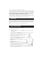
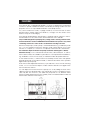
SUBMERSIBLE
WATER PUMPS
Model Nos.
CS85S - CS85SA
CS120S - CS120SA
CS185S - CS185SA
CS240S - CS240SA
CS305S - CS305SA
OPERATING & MAINTENANCE
INSTRUCTIONS
1000
CONTENTS
Warranty conditions ..................................................... 3
Safety Precautions ....................................................... 3
Electrical Connections ................................................ 4
Features ........................................................................ 5
Installation ..................................................................... 6
Maintenance ............................................................... 7
Trouble Shooting .......................................................... 8
Pump Specifications .................................................... 9 - 10
Spare Parts and Servicing ........................................... 11
SPARE PARTS & SERVICING
A range of suitable hose is available from your CLARKE dealer
For Spare Parts and Service,please contact your nearest dealer, or
CLARKE International, on one of the following numbers.
PARTS & SERVICE TEL: 020 8988 7400
PARTS & SERVICE FAX: 020 8558 3622
or e-mail as follows:
PARTS: [email protected]
SERVICE: [email protected]
2
Thank you for purchasing this Clarke Submersible Pump.
These highly efficient pumps are designed for pumping clean water, or water containing
sand or solids in suspension, (please see Features, page 5), and are ideally suited for draining
ponds, pools, building excavations etc., where water temperature does not exceed 50°C.
These pumps are NOT suitable for pumping salt water, or for permanent installation in fish
ponds as the acidity, found in fish ponds, will damage the pump seals.
Before attempting to operate your pump, please read this instruction manual thoroughly
and follow all directions carefully. This is for your own safety and that of others around you,
and to help you achieve long and trouble free service from your pump.
GUARANTEE
This product is guaranteed against faults in manufacture for 12 months from purchase date.
Keep your receipt as proof of purchase. This guarantee is invalid if the product has been
abused or tampered with in any way, or not used for the purpose for which it is intended.
The reason for return must be clearly stated. This guarantee does not affect your statutory
rights.
Please note that dismantling this pump will invalidate the guarantee
SAFETY PRECAUTIONS
1.
These pumps are designed to pump WATER ONLY. Never use for pumping flammable
liquids or chemicals of any kind.
2.
Never run the pump dry.
3.
An approved Residual Current Device (RCD) MUST be used when pumping from ponds
or swimming pools.
4.
Your submersible pump may ONLY be used for pumping water from a swimming pool
when there is no person or animal in the pool.
5.
Always disconnect the pump from the electrical supply before
placing into, or removing from the water, and before any
cleaning or maintenance of the pump.
6.
Always use the handle, with a rope or chain attached
when lifting the pump. NEVER lift thepump by the mains
cable, or, where fitted, the float switch cable.
7.
DO NOT run the pump with the body exposed for longer
than 10 minutes.
8.
DO NOT install the pump on sand, silt, mud etc., or
ground which is likely to shift.
9.
If pumping water which is below 0oC, the pump MUST be
run continuously, otherwise the pump must be removed from the
water and stored in a frost free location.
10. If the pump is to be used where there may be silt or mud (e.g., garden ponds), keep
the pump clear of any sedimentby standing it on a platform or brick or suspending
from a rope attached to the handle
3
ELECTRICAL CONNECTIONS
All models should have their mains lead connected to a standard 230Volt (50Hz) electrical
supply through an approved plug or a suitably fused isolator switch. We recommend that
these pumps be fitted with a Residual Current Device (RCD).
NOTE: This is mandatory when pump is used for pumping swimming pools and ponds
If the pump is to be connected to an outdoor electrical supply, make sure that both the
plug and the socket are of a BS approved waterproof design.
In the event that the pump is hard wired into the electrical system, it must be carried out in
accordance with IEE regulations.
If used for draining swimming pools or ponds, the pump MUST be fitted with a Residual
Current Device (RCD), with a rated residual operating current of no greater than 30mA.
WARNING: THIS APPLIANCE MUST BE EARTHED
IMPORTANT: The wires in the mains lead are coloured in accordance with the following
code:
Green & Yellow
Earth
Blue
-
Neutral
Brown
-
Live
As the colours of the flexible cord of this appliance may not correspond with the coloured
markings identifying terminals in your plug proceed as follows:
Connect GREEN & YELLOW cord to plug terminal marked with a letter “E” or
Earth symbol “ ” or coloured GREEN or GREEN & YELLOW.
Connect BROWN cord to terminal marked with a letter “L” or coloured RED
Connect BLUE cord to terminal marked with a letter “N” or coloured BLACK
FUSE RATING
The fuse in the plug for this appliance must be rated at 13 amps.
If this appliance is fitted with a plug which is moulded onto the electric cable (i.e. nonrewirable) please note:
1.
The plug must be thrown away if it is cut from the electric cable. There is a danger of
electric shock if it is subsequently inserted into a socket outlet.
2.
Never use the plug without the fuse cover fitted.
3.
Should you wish to replace a detachable fuse carrier, ensure that the correct
replacement is used (as indicated by marking or colour code).
4.
Replacement fuse covers can be obtained from your local dealer or most electrical
outlets
5.
The fuse in the plug must be replaced with one of the same rating (13 amps) and
this replacement must be ASTA approved to BS1362.
IMPORTANT:
If you are in any doubt regarding electrical installation,
you should consult a qualified electrician.
4
FEATURES
These pumps are of rugged and durable construction, designed for long lasting
continuous operation and their stainless steel bodies provide good anti corrosive
properties. The motor is provided with built in overload protection.
For your information the charts, on pages 9 and 10, show the flow rate for each
pump at various heads. (HEAD is the distance, or height, from the surface of the
water to the point of discharge)
These pumps are designed to pump water containing solids in suspension. That is with a maximum of 5% solid content, and a maximum 3mm solid dia.
They are NOT designed for pumping slurry, sludge, mud or heavily polluted water,
and should NOT be used for PERMANENT INSTALLATION in fish ponds or any water
containing chemicals or other acidic contaminants including salt water.
Whenever the pump is used to pump contaminated water, e.g. to drain fish ponds
etc., you must ALWAYS immerse the pump in clean water and run it for a few
minutes on completion, to ensure it is completely cleansed of all contaminants.
The maximum depth to which these pumps should be submerged is 5 Metres.
Automatic Pumps, i.e. those fitted with a Float Switch, denoted by an ‘A’ suffix to
their model number, are suitable for permanent or semi-permanent installations,
e.g. installations where it is necessary to maintain a water at a particular level.
As the water level rises, so will the float. At a certain point the switch will operate
and start the pump. As the water level falls, so will the float until the switch operates
again and stops the pump.
Float switches are adjusted at the factory to provide the correct ON-OFF switching
mode, i.e. cut out when the depth of water is 40mm and will cut in again when
the level reaches 300mm.
You can adjust the level at which the pump cuts out by sliding the float switch
cable through the clip attached to the main body. Shorten or lengthen it as the
case may be. The shorter it is, the earlier the pump will cut out, and the water
therefore will be deeper at this point. Similarly, it will cut in earlier and the water will
therefore be shallower when it does so.
5
It should not normally be necessary to change the length of cable (from the clamp
to the float switch), but should you do so, remember that the cable length should
NEVER be so long that the float switch fails to operate and switch the pump OFF.
ALWAYS check its operation before use.
INSTALLATION
All pumps are complete with an Outlet Hose Adapter which simply screws into the
outlet port on top of the pump body.
Model CS85 is provided with a 1”BSP threaded adapter which will accept a 1”
I.D. hose.
Models CS120 and 185 are provided with a 1¼”BSP threaded, two stage adapter,
which will accept either a 1” or 1 ¼” I.D. hose.
Models CS240 and 305 are provided with a 1½” BSP threaded adapter which
will accept a 1½” I.D. hose.
Ensure the hose is secured with a suitable worm drive clip (not supplied).
If the pump is to be used for drainage purposes, or in situations that demand
maximum efficiency, we strongly recommend that you connect the largest
diameter hose possible to the outlet hose adapter, as small diameter hoses reduce
capacity and put additional strain on the motor.
If a 1¼” hose is used with models CS120 & 185, it will be necessary to cut off the 1”
diameter fitting at the joint between the two. Do not slide the 1¼” hose over the
1” fitting as the 1” fitting will act as a restriction.
The pumps are completely submersible and must be placed in a vertical position
on a solid flat surface. If this is not available, sit the pump on house bricks, or
something similar, and ensure that this type of support is not likely to shift.
The pump should be well clear of silt, mud or any type of marine growth.
IMPORTANT:
ALWAYS raise and lower the pump using a rope attached to the lifting eye,
where fitted, or to the lifting handle, NEVER by the power cable.
Automatic versions should be placed in a sump which has adequate dimensions
so as not to restrict the movement of the float switch.
Please note that the symbo
on the pumps’ Rating Plate, denotes the MAXIMUM
depth to which the pump may be submerged, in metres.
Take all necessary precautions as described on page 2 before plugging in, and
switching ON.
SUITABLE HOSE, and SPARE/REPLACEMENT HOSE ADAPTERS ARE AVAILABLE FROM
YOUR CLARKE DEALER
6
MAINTENANCE
WARNING
Before checking the condition of the pump, ensure it is unplugged from the
mains supply. If the unit is hard wired, ensure the circuit breaker is open.
Check the pump installation regularly to ensure the base inlet is clear of leaves or
other debris.
Note that these pumps are fitted with automatic thermal overload protection. If
the pump overheats due to an obstruction in the pump, or pumping warm water
in excess of 50oC for example, it will shut off automatically. Switch the pump OFF
and disconnect from the mains supply. Check for blockages and allow the motor
to cool (at least 15 minutes) before attempting to restart.
These pumps should require no maintenance other than regular cleaning. If the
pump starts to show signs of wear or damage, contact your CLARKE dealer for
advice. Do not use the pump if there is any damage to the mains supply cable, or
to the float switch or its cable.
Do not attempt to repair the pump yourself, as you may damage the waterproof
seal and invalidate your guarantee. Repairs must be carried out by your CLARKE
dealer, or contact the CLARKE Service Department, on 0208 556 4443.
If the pump becomes badly clogged, the stainless steel strainer may be removed
and cleaned by removing the screws, on the underside of the strainer, which
secure it to the main body.
Back flush the pump by removing the inlet hose adapter and directing a jet of
clean water through the inlet port.
IMPORTANT
Do not attempt to strip the pump further as this will invalidate the guarantee
7
TROUBLE SHOOTING
A. PUMP WILL NOT START
1.
Manual type (i.e. without float switch)
1.1 Check to ensure Power is switched on.
1.2 Check fuse (consult an electrician if in doubt).
1.3 If extension lead is fitted, check connections (consult an electrician if in
doubt).
1.4 Internal thermal cutout has not reset. Leave for 5 minutes and try again.
1.5 The Impeller may be jammed. Disconnect from the mains supply, remove
the bottom strainer and remove any objects that may be obstructing the
impeller. Replace the strainer and try again.
If the pump still fails to start, consult your CLARKE dealer for advice.
2.
Automatic Type (with float switch)
2.1 Check all above.
2.2 Float switch may be jammed against side wall, or prevented from moving.
2.3 Water level too low - float switch in OFF position - Lift float to check switch.
B. PUMP WILL START BUT NOT PUMP
1.
Water level too low - below the minimum suction level (Manual type).
2.
Check to ensure strainer is not blocked.
3.
Discharge tube clogged or obstructed.
4.
The head may be too great, i.e. you are trying to lift the water too great a
distance for the pump to cope with. (See specifications pages 9 -10 ).
5.
Air bubble in the pump, produced during the plunge. Plunge the pump again,
at an angle, and shake it whilst lowering to remove any air trapped in the system.
6.
Impeller may be damaged - Consult your CLARKE dealer
C. AUTOMATIC PUMP WILL NOT STOP
1.
Float switch may be prevented from moving to the fully down position.
2.
Float switch may be faulty. Consult your CLARKE dealer for advice.
D. PUMP STOPS RUNNING
1.
Thermal overload has operated. If this condition persists, investigate the cause.
Are you attempting to pump liquid which is too heavy for the pump (mud, slurry
etc.)
2.
Pump has run dry, or float switch has cut in.
3.
A foreign object has jammed the impeller.
8
PUMP PERFORMANCE DATA
CS85S & CS85SA
Outlet Dia. ................................. 1”/25mm
Motor Output ............................ 250Watts
Motor Speed ............................. 2,800RPM
Head Max. ................................ 6M
Max. Submersion Depth .......... 5M
Max. Capacity ......................... 80L/min
Weight ....................................... 3.3/3.5kg
Cable ........................................ 10M
Dimensions* .............................. 155x212mm
Part No.
CS85S ..................... 7239100
CS85SA .................. 7239105
*Diameter x Height
CS120S & CS120SA
Outlet Dia. ................................. 1¼”/ 32mm
Motor Output ............................ 300Watts
Motor Speed ............................. 2,800RPM
Head Max. (M) ......................... 6M
Max. Submersion Depth .......... 5M
Max. Capacity ......................... 115L/min
Weight ....................................... 5.2/5.5kg
Cable ........................................ 10M
Dimensions* .............................. 154X238mm
Part No.
CS120S ................... 7239110
CS120SA ................ 7239115
*Diameter x Height
CS185S & CS185SA
Outlet Dia.
1¼”/ 32mm
Motor Output
450Watts
Motor Speed
2,800RPM
Head Max
8M
Max. Submersion Depth
5M
Max. Capacity
160L/min
Weight
5.9/6.2kg
Cable
10M
Dimensions*
154x238mm
Part No.
CS185S ................... 7239120
CS185SA ................ 7239125
*Diameter x Height
9
CS240S & CS240SA
Outlet Dia. ............................... 1½”/ 38mm
Motor Output .......................... 600Watts
Motor Speed ........................... 2,800RPM
Head Max. .............................. 11M
Max. Submersion Depth ........ 5M
Max. Capacity ....................... 215L/min
Weight ..................................... 8.7/9.0kg
Cable ...................................... 10M
Dimensions* ............................ 212x290mm
Part No.
CS240S .............. 7239130
CS240SA ........... 7239135
*Diameter x Height
CS305S & CS305SA
Outlet Dia. ................................. 1½”/ 38mm
Motor Output ............................ 750Watts
Motor Speed ............................. 2,800RPM
Head Max. ................................ 14M
Max. Submersion Depth .......... 5M
Max. Capacity ......................... 300L/min
Weight ....................................... 10.7/11.0kg
Cable ........................................ 10M
Dimensions* .............................. 212x290mm
Part No.
CS305S ................ 7239140
CS305SA ............. 7239145
*Diameter x Height
10