1
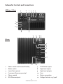
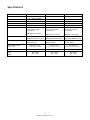
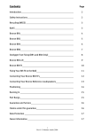
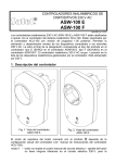
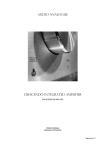
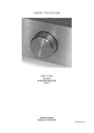
SUBWOOFER OWNERS MANUAL
24 Brook Road, Rayleigh, Essex SS6 7XL. England.
Tel: +44 (0) 1268 740580 Fax: +44 (0) 1268 740589
[email protected]
www.monitoraudio.co.uk
SUBWOOFER OWNERS MANUAL
ASW100/FB110/FB210
Monitor Audio Subwoofers
Thank you for purchasing your Monitor Audio subwoofer, we trust it will enable you
to have hours of continuous pleasure.
All our speakers are hand crafted from top to bottom in our factories in England.
Established in 1972, Monitor Audio has extensive experience in the use of
traditional woodworking skills for our cabinets and state of the art technology for
our drive units.
Music is and should be a natural enhancement of life. It stimulates the imagination,
changes your mood, helps you relax, and provides endless hours of entertainment.
Now in the 21st century we pride ourselves in the quality and versatility of our
loudspeakers. Monitor Audio have removed the need for compromise by offering
attractive solutions for both stereo and hometheatre applications.
Important:
Owing to the sophisticated construction of the subwoofer drive units, a running in
period of approximately 60 hours should be expected before the optimum
performance is achievable.
Guarantee and Service
Valid upon completion of the guarantee card and its return within 30 days of
purchase.
This equipment has been fully tested prior to despatch from the factory. Both the
craftmanship and the performance of this product is guaranteed against
manufacturing defects for the period of one year from the date of purchase (see
conditions below) and that the product was supplied by an authorised Monitor
Audio retailer under the consumer sale agreement.
(The words ‘consumer sale’ shall be construed in accordance with section 15 of the
supply of goods act 1973).
Monitor Audio accepts no responsibility for defects arising from accident; misuse,
abuse, wear and tear, modification or operation outside of that specified within this
instruction manual. Neither will responsibility be accepted for damage or loss
occurring during transit to or from the parties claiming under this guarantee.
This guarantee covers both labour and parts. The liability of Monitor Audio is
limited to the cost of repair or replacement of the defective parts (at the discretion
of Monitor Audio) and under no circumstances extends to consequential losses or
damage.
Claims under this guarantee
The equipment should be returned in its packing to the original supplier where
possible, or to any other authorised Monitor Audio dealer. If it is not possible to
return the equipment by hand, then it should be sent carriage prepaid via a
reputable carrier. If the original packing is not available replacement packing can be
purchased from Monitor Audio. If you have any difficulties complying with these
requirements please contact us at the following address:
Monitor Audio Ltd
24 Brook Road, Rayleigh, Essex SS6 7XL England
Tel:
+44 (0) 1268 740580
Fax:
+44 (0) 1268 740589
Email:
[email protected]
Web:
www.monitoraudio.co.uk
You may wish to visit our website which gives full details of our complete range of
products.
This guarantee does not affect the statutory rights of the consumer under UK law.
Monitor Audio reserve the right to alter specifications without notice if considered
an improvement can be made to the product.
17
© Monitor Audio Ltd 2001
Contents
What we have provided in this Owners Manual
Page
2
Unpacking and Installation
3-4
Safety Instructions
5
Mains Connection
6-8
Subwoofer Controls and Connections
9
Standard amplifier - speaker cable connection
10
Satellite Speaker wiring option 1
11
Speaker level high pass filter
12
Main/Satellite speaker wiring option 2
13
Wiring with a pre amp and separate power amp
14
Plugging in the Subwoofer
14
Fine tuning
15
Trouble shooting
16
Specifications
17
Guarantee and Service
17
Claims under Guarantee
1
© Monitor Audio Ltd 2001
Unpacking & Installation
Lift out the subwoofer unit from the packaging, care must be taken not to depress
the drive unit cones as this could result in permanent damage. Fix the four feet to
the underside with the screws provided. The subwoofer unit should be positioned
in the most suitable position, preferably not in the corner of a room as this may
cause a pronounced boom. It is important to position the subwoofer initially to have
easy access to the control panel.
After you have chosen your desired connection method it is important to note that
all your cables will reach easily. Leave the subwoofer unplugged until the
installation and initial set-up procedure is complete.
The optimal control settings will depend entirely on your system configuration.
For initial trials set the controls as follows:
Gain
should be set to the minimum position.
Frequency
should be set to approximately 60 Hz, if you have large main speakers.
If you have small main speakers or satellites, this should be set to
approximately 100Hz.
Phase
should be set to initial 0 degrees.
Mode
If you prefer an audio quality performance the mode switch should be
left in audio. If you are installing a predominately home cinema
system it may be more effective to set mode switch to video position.
Note: This Subwoofer unit is fitted with a switchable voltage selector, which
should be factory set. If you are in any doubt as to your mains supply voltage specification you must consult the dealer from where you purchased the product. Under
no circumstances should the voltage selector be altered.
See: Mains voltage chart under specifications on page 16.
Note: If the Subwoofer is not likely to be used for long periods, it is wise to switch
off at the mains. This is a recommended safe practice in order to reduce the risk of
electrical fire.
2
© Monitor Audio Ltd 2001
Monitor Subwoofers
Safety Instructions
1
Read Instruction
All the safety and operating instructions in this Manual should be read before
the appliance is operated.
2
Retain Instructions
Retain this Owners Manual for future reference.
3
Note Warnings
All warnings on the appliance should be adhered to.
4
Follow the Instructions
All operating instructions should be followed
5
Water and Moisture
The appliance should not be used near water - for example, bathtub, wash
bowl, kitchen sink, washing machine, in a wet basement or near a swimming
pool. Under no circumstance should plants or fish bowls be placed on the
appliance.
6
Positioning
The appliance has been designed for floor mounting only.
7
Ventilation
The appliance should be situated so that its location or position does not
interfere with its own proper ventilation. For example, the appliance should
not be situated on a sofa, bed, rug or similar surface that may impair any
ventilation openings. It should not be placed in any purpose built location
without suitable ventilation being provided.
8
Heat
The appliance should not be placed near any heat source such as radiators,
open fires, stoves, direct sunlight and any other appliance that produces heat.
9
Power Sources
The appliance should be connected to a power supply only of the type
described in the operating instructions or as marked on the product.
3
© Monitor Audio Ltd 2001
10
Power Cord Protection
Power supply cords should be routed so that they are not likely to be stepped
on or pinched by items placed upon or against them, paying particular
attention to cords at plugs, convenience receptacles and the point where the
cable exits the appliance.
11
Non Use Periods
The power cord of the appliance should be unplugged from the mains outlet
when left unused for a long period of time.
12
Cleaning
While cleaning is in progress the AC mains power lead should be unplugged
from the AC supply. The appliance can be cleaned with a soft dry cloth.
13
Liquid Entry
Care should be taken to ensure that no liquid is spilt on the appliance,
especially near the rear panel where the power cord enters the appliance.
14
Damage Requiring Service
Qualified personnel should service the appliance when:
a
b
c
The power cord or the plug has been damaged.
Liquid has been spilt on to the rear panel of the appliance.
The appliance does not appear to operate normally or exhibits a marked
change in its performance.
The appliance has been dropped or the enclosure damaged.
d
15
Servicing
The user should not attempt to service the appliance beyond that specified in
the operating instructions. Qualified service personnel should carry out all
other servicing requirement.
4
© Monitor Audio Ltd 2001
Mains Connection
Important
Check the voltage setting. Do not connect the appliance to an incorrect power
supply, as serious damage may occur. Do not connect the power supply until all
other connections have been made.
Position/Location
Your Monitor Audio Subwoofer should perform well in just about any room location.
In fact unless your ear is within a couple of feet of the subwoofer, the bass should
seem to radiate from your main speakers.
Your Monitor Audio Subwoofer is not magnetically shielded and therefore should
not be located too close to your television set, leave a distance of at least 2-3 feet.
Failure to do so will result in your television set’s tube becoming magnetised and
this will cause a distortion of the picture, together with a change of colour. Should
this occur, consult your Television service agent for advice.
No matter where you place your subwoofer, you must allow sufficient spacing for
ventilation of the rear panel. The rear panel has a heat sink mounted onto it and will
therefore generate heat, when in use.
Do Not
a
Place your subwoofer directly against a wall, leave at least a minimum of 15cm
(6 inches) and preferably 30cm (12 inches).
b
Place against a radiator, panel heater or forced air heating outlet
c
Place outdoors or in a humid environment
d
Plug into an AC mains outlet until all your system wiring is completed.
5
© Monitor Audio Ltd 2001
Subwoofer Controls and Connections
ASW 100 / FB110
9
8
2
5
4
3
1
12
11
7
10
1
6 7
2
FB 210
4
3
5
8
9
12
11
10
1
2
3
Power switch with auto off facility
Mode switch
Level/Gain control
7
8
9
RCA Phono inputs
High level inputs
High level outputs
4
5
6
Crossover/Frequency control
Phase control
RCA Phono outputs
10
11
12
Fuse
Mains connection
Voltage Selector 115/230V
6
© Monitor Audio Ltd 2001
Subwoofer connections
There are a number of ways to connect your subwoofer into your system. One uses
loudspeaker cables, the other uses interconnect cables with RCA phono plugs.
Looking at the rear panel of your subwoofer you will see two sets of speaker
terminals, one labelled ‘high level input’, the other ‘high level output’, and RCA
phono socket labelled ‘input’ (left and right).
The configuration of your system will determine how you will connect your
subwoofer.
1. Power Switch with Auto Off facility: The power switch provided for
ASW100/FB110 has two positions: Off - Auto On. In the Auto On position the subwoofer unit will remain in stand by mode until the unit receives an input signal. If
the subwoofer unit does not receive a signal for around 15-20 minutes, it will switch
to stand by mode until it receives a further signal. The FB210 is provided with a three
position switch, which also has a permanently ‘On’ position
2. Mode switch: This facility is used to set the desired gain level for your music or
home cinema system. Factory set in the audio position, the subwoofer possesses an
optimum frequency response for music playback. In the video mode the output is
increased by 3dB at 30Hz in order to allow for a greater impact to cinema material.
3. Level/Gain: This control allows the subwoofer level or loudness to be adjusted in
order that you can achieve a totally controlled balanced sound. To use this feature,
firstly take a selection of your favourite music with good bass content and listen,
judge the bass quality and content and whether or not the level is integrated with
the main/satellite speakers. Once you achieve the correct integration in your
system then there should be no further reason to touch this control.
4. Crossover/Frequency: This feature controls the frequency at which the subwoofer
rolls off. This should be set in conjunction with the fine tuning instructions.
5. Phase: The phase control is used to synchronise the phase of the subwoofer and
the main/satellite speakers. Monitor Audio choose to use a linear potentiometer
rather than the standard 0/180 degree switch to enable perfect tuning between the
subwoofer and the front main speakers. However, this depends on the position of
the subwoofer in relation to the front main/satellite speakers and their types, i.e.
bass frequency and type. Simply using a switch between 0 and 180 degrees, as with
most subwoofers, is insufficient for optimising a perfect balance, as the correlation
factors are considerable.
What to listen for? The point at which the subwoofer is in phase with the main/
satellite speakers, the sound should be full bodied and integrated. At this point the
subwoofer should almost be undetectable. Experimentation is advisable in order to
obtain the optimum result.
NB Re-adjusting the crossover frequency should also be considered.
7
© Monitor Audio Ltd 2001
6. RCA Phono Output (FB210 only): This facility can be used to link out to an
additional power amplifier. The RCA phono output can also be used to daisy chain a
number of sub woofer units together.
7. RCA Phono Input Connection: This method of connection is recommended for
optimum performance. Input should be provided at line or signal level from a
pre-amplifier or A.V. receiver. It is not advisable to run cable lengths of more than 10
metres, as this will introduce a degree of noise and attract interference from other
appliances. Both left and right inputs are buffered and added together internally. In
the case of an A.V. receiver with a dedicated ‘sub-out’ connection, only one length
of cable can be run to the left input connection.
8. High Level Input: This facility provides the sub-woofer with connection directly
from the amplifier output terminals.
Note: A maximum input of 150watts, when using the high level input connection
method.
9. High Level Output: When the high level input connection method is used, the
output to the main speakers is provided by the high level output.
Note: The high level output is filtered from 100Hz@6dB/octave, which reduces the
overall bass energy transferred to the main speakers. This facility allows higher
sound pressure levels from the system, this is particularly useful when using small
satellite speakers.
10. The mains fuse should be replaced with one of the exact specification.
Note: A spare fuse is provided within the fuse holder. If a fuse blows more than
once, it is advisable to have the subwoofer unit checked by an
authorised service agent.
11. Mains connection is provided by 3 pin IEC style socket.
12. Mains Voltage Selector should be factory set to your countries mains voltage
specification. Do not attempt to adjust this as this may lead to permanent damage
to the product and even the risk of fire.
8
© Monitor Audio Ltd 2001
Standard amplifier - speaker cable connection
This method will involve connecting your subwoofer to the amplifier using
loudspeaker cables. To do this you make the same kind of connections that you
would use for your main / satellite speakers, except both your left and right
channels go to the subwoofer.
1
Connect the amplifiers left channel Red (+) to the subwoofer left channel Red
(+) ‘high level input’ terminals.
2
Connect the amplifiers left channel Black (-) to the subwoofer left channel
Black (-) ‘high level input’ terminals.
3
Make a corresponding match connection to the right channel.
See fig. 1 (showing ASW100/FB110)
(If using two subwoofers connect one to each channel)
Fig. 1
AMPLIFIER
SPEAKERS
L
R
9
© Monitor Audio Ltd 2001
Satellite speaker wiring option 1
With this option, you connect the wiring for the main/satellite speakers directly to
the subwoofer. There is no performance advantage in wiring your system this way,
it may just be a factor of convenience, remembering to keep the speaker cables
approximately the same length to avoid different loading to the amplifier.
1
Connect the subwoofer Red (+) ‘high level output’ terminal to the Red (+)
terminal on the back of the left main / satellite speaker.
2
Connect the subwoofer Black (-) ‘high level output’ terminal to the Black (-)
terminal on the back of the main / satellite speaker.
3
Make a matching connection to the right channel main/satellite.
Fig. 2
AMPLIFIER
SPEAKERS
L
R
MONITOR AUDIO
MONITOR AUDIO
LEFT
SPEAKER
RIGHT
SPEAKER
10
© Monitor Audio Ltd 2001
Speaker-level high pass filter
Monitor Audio’s subwoofers have a high pass filter. When your main/satellite
speakers are connected to the ‘speaker output’ terminals on the subwoofer, the low
bass frequencies below 100Hz are filtered from your main / satellite speakers.
This filter significantly reduces the bass demands placed on your main / satellite
speakers and can make a considerable improvement in their sound quality,
especially in the mid-bass and lower midrange. The filter may make subtle changes
to the sound quality, you may wish to experiment with or without the filter to
determine the best configuration for your system.
To use the filter, connect as speaker wiring option 1. See Fig 2.
If you have a Dolby Pro-Logic system, we recommend that you set the centre
channel switch on the processor to the normal mode. This provides a low bass filter
for the centre channel speaker and also insures that the bass from all three front
channels is fed to the subwoofer.
This high-pass filter does not operate when the subwoofer is connected using
interconnect cable (RCA phono).
11
© Monitor Audio Ltd 2001
Main/Satellite speaker wiring option 2
This option has the main/satellite speakers directly connected to the amplifier. This
requires 2 sets of speaker cables, one set running to the main / satellite speakers
and the other running to the subwoofer. If your amplifier has only one set of
speaker terminals you can connect the main / satellite speakers to your amplifier
using the same high level output terminals as the subwoofer. Do not connect the
main / satellite speakers to the subwoofer.
Fig. 3
SPEAKERS
AMPLIFIER
L
R
MONITOR AUDIO
MONITOR AUDIO
LEFT
SPEAKER
RIGHT
SPEAKER
12
© Monitor Audio Ltd 2001
Wiring with a pre amplifier and separate power amplifier
The ‘pre-amplifier’ RCA input phono sockets on the subwoofer, allows you to
directly connect the subwoofer to line level components such as pre-amplifier,
integrated amplifier and surround sound processors with pre-amplifier outputs. If
you only have one set of pre-amplifier outputs you will need to have a Y connector
(split lead) to feed both the amplifier and subwoofer. The high level output filters do
not work when RCA phono inputs are used.
To connect the subwoofer in this way, simply run a set of shielded RCA - RCA
interconnect cables from the output sockets of your component to the ‘input’
sockets (left and right) on the subwoofer rear panel. See Fig. 4 if you are using two
subwoofers, simply connect one subwoofer per channel.
Fig. 4
PREAMP
L
R
L
MAIN
OUT 1
POWER AMP
SPEAKERS
L
L
R
MAIN
OUT 2
R
R
MAIN
INPUT
MONITOR AUDIO
MONITOR AUDIO
LEFT
SPEAKER
RIGHT
SPEAKER
13
© Monitor Audio Ltd 2001
Plugging in the Subwoofer
Once all the speaker cables are in place you are ready to plug in the subwoofer. Set
the bass level to minimum then plug in your mains cable. At switch on your
subwoofer will be in stand-by mode. The subwoofer will remain in stand-by mode
until a signal is sensed at the input. If the subwoofer is not active for a period of
around fifteen minutes, the unit will switch back into stand-by mode.
Fine-tuning
Play the music at an average listening level, the Subwoofer should switch on
automatically. The phase control must be set first, rotate the phase control slowly,
listening for the point at which the bass sounds full and integrated. The sound from
the subwoofer should be almost undetectable. Once this is set you should not need
to reset this again. Next, alter the gain control for the optimum loudness level.
The frequency control can now be set to give a seamless sound balance; this may
take some time and patience. The gain may need to be fine-tuned to complete the
installation process. It is very important to try a variety of music software, with
which you are familiar in order to obtain the optimum overall settings.
Note: If the Subwoofer is not likely to be used for long periods, it is wise to switch
off at the mains. This is a recommended safe practice in order to reduce the risk of
electrical fire.
14
© Monitor Audio Ltd 2001
Troubleshooting
No sound from the subwoofer
•
•
•
•
Check that the power connection is made correctly
Check to see if the power light is on
Check the input connections to the subwoofer are correct
If the high level input is in use, check the connections are phased
Excessive bass from subwoofer
•
•
Check the position of subwoofer - ensure that it is not too close to a corner of
the room
Re-check the setting up procedure
Inadequate bass from subwoofer
•
Re-check full setting up procedure
Vibrating noise from subwoofer
•
Check that this is not caused by items located on top of or close to the
subwoofer which may vibrate when subject to deep bass sounds
If problems persist contact your dealer immediately for assistance.
15
© Monitor Audio Ltd 2001
Specifications
Low Frequency Limit
Upper Frequency Limit
Amplifier Output
Input Impedance Line Level
Speaker Level
Filter Characteristics
ASW 100
FB 110
27 Hz
26 Hz
25 Hz
40 - 180 Hz Variable
40 - 180 Hz Variable
40 - 180 Hz Variable
FB 210
120 W
150 W
200 W
10K Ohms
10K Ohms
10K Ohms
>100K Ohms
>100K Ohms
>100K Ohms
Active 4th Order/24dB Per
Octave Linkwitz-Riley
Linear Phase
Active 4th Order/24dB Per
Octave Linkwitz-Riley
Linear Phase
Active 4th Order/24dB Per
Octave Linkwitz-Riley
Linear Phase
6 dB/Octave @ 120 Hz
6 dB/Octave @ 120 Hz
6 dB/Octave @ 120 Hz
Input
RCA, Line Level, 4mm
Binding Post Speaker Level
RCA, Line Level, 4mm
Binding Post Speaker Level
RCA, Line Level, 4mm
Binding Post Speaker Level
Driver Complement
1 x 10” Paper cone
Sub-Bass Driver
1 x 10” Magalloy
Sub-Bass Driver
2 x 10” Magalloy
Sub-Bass Driver
External Dimensions
(H x W x D)
33 x 32 x 32 cm
13” x 121/2” x 121/2”
37 x 37 x 37
141/2” x 141/2” x 141/2”
50 x 37 x 37
193/4” x 141/2” x 141/2”
Weight
12Kg / 26lb
15Kg / 33lb
24Kg / 53lb
Input Voltage (Mains)
115V
230V
90 - 125V
220 - 250V
90 - 125V
220 - 250V
90 - 125V
220 - 250V
16
© Monitor Audio Ltd 2001