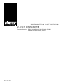
1
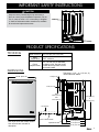
Install ation Instructions 24 - Inch Dishwasher For use with models: ED24, ID24, MDH24, MDV24, PD24AG, PD24BK, Part No. 101891 Rev. F PD24BU, PD24GN, PD24SG, PD24TS TABLE OF CONTENTS Before You Begin............................................................... 1 Important Safety Instructions........................................ 1-3 Product Specifications...................................................... 3 Technical........................................................................... 3 Dimensions....................................................................... 3 Preparing for Installation................................................ 4-5 Preparing the Location...................................................... 4 Power Supply Preparation................................................ 5 Plumbing Preparation........................................................ 5 Preparing the Drain........................................................... 5 Installation Instructions................................................ 6-12 Verify the Package Contents............................................. 6 Electrical Connection..................................................... 7-8 Plumbing Connections...................................................... 9 Installing the Unit in the Cabinet.................................. 9-10 Drain Line Installation......................................................11 Verifying Proper Operation.............................................. 12 Before You Begin... IMPORTANT: If you have questions or problems with installation, contact your Dacor ® dealer or the Dacor Customer Service Team. Installer: In the interest of safety and to minimize problems, read these installation instructions completely and carefully before you begin the installation process. Leave these installation instructions with the customer. Dacor Customer Service Customer: Keep these installation instructions for future reference and the local electrical inspector’s use. Phone: Email: Web site: (800) 793-0093 [email protected] www.Dacor.com All specifications are subject to change without notice. Dacor assumes no liability for changes to specifications. Important Safety Instructions Safety Symbols and Labels Important Information About Safety Instructions The Important Safety Instructions and warnings in these instructions are not meant to cover all possible problems and conditions that can occur. Use common sense and caution when installing, maintaining or operating this or any other appliance. Always contact the Dacor Customer Service Team about problems and conditions that you do not understand. DANGER Indicates immediate hazards that WILL result in severe personal injury or death. WARNING Indicates hazards or unsafe practices that COULD result in severe personal injury or death. CAUTION Indicates hazards or unsafe practices that COULD result in minor personal injury or property damage. DANGER To avoid the possibility of explosion or fire, do not store or use combustible, flammable or explosive vapors and liquids (such as gasoline) inside or in the vicinity of this or any other appliance. Do not store flammable or explosive materials in adjacent cabinets or areas. warning The customer should not install, repair or replace any part of the dishwasher unless specifically recommended in the literature accompanying it. A qualified service technician should perform all other service. Contact the nearest Dacor authorized service representative at (800) 793-0093, or at www.Dacor.com for examination, repair or adjustment. Important Safety Instructions To reduce the risk of fire, electric shock, serious injury or death when using the dishwasher, follow basic safety precautions, including the following: WARNING 1. Do not install or operate this dishwasher if it has been damaged, dropped, has damaged electrical conduit or wires or is not working properly. If the product is damaged when received, immediately contact the dealer or builder. 2. Use this dishwasher only for its intended purpose as outlined in the use and care manual. It is not intended for commercial use. Read the use and care manual completely before use. 3. Keep all packaging materials away from children. Plastic bags can cause suffocation. 4. To avoid electric shock, this dishwasher must be installed and grounded by a qualified installer in a completely enclosed cabinet according to these installation instructions. 5. All installation work, plumbing connections and electrical wiring must be performed in accordance with all applicable codes and standards. 6. Install or locate this appliance only in accordance with these installation instructions. 7. The installer must show the customer the location of the fuse box or circuit breaker panel so that the customer knows where and how to turn the power off. 8. Before installing or servicing the dishwasher, switch power off at the fuse box or circuit breaker panel and lock the electrical panel door to prevent power from being switched on accidentally. When the circuit breaker panel cannot be locked, securely fasten a prominent warning device, such as a tag, to the electrical panel. 9. Do not tamper with the controls. 10. Do not leave children alone or unattended in the area where the dishwasher is in use. Never allow children to sit or stand on an appliance. Do not let children play with this appliance. 11. Never allow anyone, including children, to sit or stand on any part of the dishwasher. Stepping or sitting on any part of it may result in tipping, damage and serious injury. 12. Many surfaces within the dishwasher achieve high temperatures. Do not touch interior surfaces or items inside the dishwasher during or immediately after use. Exercise caution when opening the door. Let hot air and steam escape before looking or reaching inside. 13. Do not operate the dishwasher without the door completely closed and the toe kick panel in place. 14. Store all detergents and rinse aids out of the reach of children. 15. During loading, insert all sharp or pointed objects with the handles up. Locate these items where they will not damage the door seal or cause personal injury. 16. Do not tamper with the controls. 17. Under certain conditions hydrogen gas may be produced in a hot water system that has not been used for two weeks or more. Hydrogen gas is explosive. If the hot water system has not been used for a period of time, turn on all hot water faucets and let the water flow for several minutes to release any accumulated hydrogen gas. Do not smoke or use an open flame during this process. 18. To prevent child entrapment, always remove the door from an old dishwasher when removing it from service. 19. To prevent household mold and mildew damage, periodically check the inlet and drain hoses for leaks. 20. If the dishwasher outlet is connected to a garbage disposal, make sure the disposal is completely empty before running the dishwasher. 21. To avoid damage to the racks, do not let sharp edges come into contact with them. 22. This appliance is designed for installation by more than one person. To avoid personal injury, do not attempt to move or lift the dishwasher without assistance. 23. To prevent personal injury and damage to the unit due to it tipping over, do not push down on the door anytime it is open. To reduce the chance of tipping, attach the anti-tip brackets to the cabinet before operation. Important Safety Instructions CAUTION Keep the factory installed high loop drain hose in place to ensure proper dishwasher operation. Do not cut, tie, strap or lower it. If it is necessary to lengthen it, install an aftermarket drain extension kit, available at most home improvement stores. Product Specifications Technical Water Pressure 20 to 120 psi (138 - 827 kPa) Water Temperature Power Requirements 120°F, minimum 15 A, 120 Vac, 60 Hz dedicated, grounded, circuit. See the model number label on product for total connected loaded. Dimensions 1 1/8” (2.9 cm) 23 7/8” (60.6 cm) Tolerances: +1/16”, -0, (+1.6 mm, -0) unless otherwise stated 2 3/8” (6. 0 cm) 26" (66.0 cm) ED24: 29 5/8" (75.2 cm) ID24: 26 7/8" (68.3 cm) 33 3/4" (85.7 cm) to 36 1/4" (92.1 cm) 1 1/2” (3.8 cm) Door in Lowered Position Door style varies with model number. See use and care manuals for description. Adjustable Toe Kick 19 3/8" (49.2 cm) 23 1/2" (59.7 cm) 46 1/2" (118.1 cm) Preparing for Installation WARNING • Observe all governing codes and ordinances during planning and installation. Contact your local building department for further information. Preparing the Location Carefully check the location where the dishwasher is to be installed. Put it in a location with convenient access. Make certain that electrical power can be provided in the selected location. Plan the installation so that the appliance can be removed if service is required. IMPORTANT: Follow all cabinet and countertop minimum dimensions shown below to insure safe operation. Prepare the installation location as shown below. All minimum product dimensions be must met or exceeded (see page 3). Dimensions shown provide minimum clearances, unless otherwise noted. The floor must be level and all cut-out surfaces must be at right angles. The dishwasher must be secured to the adjacent cabinets using the anti-tip brackets for safety and proper operation. Min. Countertop 25" (63.5 cm) Fasten anti-tip anchors into material under counter top and adjacent cablinets 90° 90° 33 3/4” (85.7 cm) to 36 1/4” (92.1 cm) 24” (61.0 cm) Access Hole for Utilities 8” H X 5“ D (20.3 cm X 12.7 cm) 24” (61.0 cm) CUT-OUT FRONT VIEW CABINET INSTALLATION SIDE VIEW Preparing for Installation Power Supply Preparation WARNING • The electrical power supply for the dishwasher must be installed only by a licensed electrician as specified below. It is the owner’s responsibility to ensure that the electrical connection of this appliance is performed by a licensed electrician. Plumbing Preparation • The water pressure must be between 20 and 120 psi (138-827 kPa). The household hot water heater should supply a minimum of 120°F water to the dishwasher location for best results. • Install a water supply valve for the hot water supply line where it is easily accessible after the dishwasher is installed. The dishwasher is shipped with a 3/8 male compression fitting to facilitate installation. Electrical Specifications The electrical installation, including minimum supply wire size and grounding, must be in accordance with the National Electric code ANSI/NFPA* (or latest revision) and local codes and ordinances. *A copy of this standard may be obtained from: National Fire Protection Association 1 Batterymarch Park Quincy, Massachusetts 02269-9101 Power supply requirements: • The dishwasher requires a grounded, dedicated 120 Vac, 60 Hz circuit protected by a 15 A circuit breaker or time delay fuse installed by a licensed electrician. • It must be located to the right or left of the cut-out, in an adjacent cabinet, so that power can be disconnected without removing the dishwasher. • The ground terminal (or lead) on the appliance must be connected to a grounded, metallic, permanent wiring system or grounding conductor installed by a licensed electrician. • Do not ground the appliance or appliance wiring to a gas pipeline or to the neutral (white) power supply wire. • Do not install a fuse in the neutral or ground circuit. The dishwasher can be connected to: A UL/CSA approved, grounded, three-prong receptacle (if local code permits). This method is the easiest to install. OR Directly to the house wiring. Hard-wire the dishwasher according to local code directly to a three wire grounded, single phase connection in a junction box. Hot Water Inlet • • • Have a licensed electrician prepare the electrical receptacle or junction box for final connection inside the adjacent cabinet according to the specifications above. If copper tubing is present from a prior installation, remove it and replace it with a flexible braided hose. Preparing the Drain IMPORTANT: A drain line hose is supplied with the product. Should a longer drain hose be required, use a hose approved for detergents and high temperature water. The drain hose supplied with the dishwasher meets an AHAM DW-1 test standard. Longer drain hoses should not be longer than 12 ft. in length. • You must install an air gap in the drain if the drain hose is connected to household plumbing lower than 20 in. (50.8 cm) from the floor or if required by local codes. Plan for the air gap in the sink or countertop area adjacent to the dishwasher. A section of drain hose (not provided) needs to be installed from the air gap to the disposal or waste tee. • If an air gap is not required, the drain hose must be installed to an inlet or waste tee above the drain trap in the household plumbing. • The drain hose supplied with the dishwasher should be connected to a minimum 1/2 in. I.D. drain connection. • If the drain is connected to a disposal, see the disposal manufacturer’s installation instructions for correct drain hose mounting techniques. NOTE: In either case, be sure the power cable or wire is long enough to remain connected when the appliance is removed from the cut-out for service. If the electrical service does not meet the specifications above: BACK OF DISHWASHER A flexible braided fill hose is highly recommended. Connect it to the unit just prior to installation into the cabinet. Installation Instructions Verify the Package Contents NOTE: Model ID24 ships without a front panel. It is designed for the installation of an integrated front panel that matches the surrounding cabinets. • With the assistance of at least one person, remove the dishwasher from the shipping carton. Place the unit to the side of the cabinet opening. • Remove all of the packing materials from inside and outside of the unit. DO NOT allow any of the shipping materials, loose screws or plastic to remain inside. Remove the racks. Set them aside for later installation. • Unpack the parts box and verify that all required components have been provided. If any item is missing or damaged, please contact the dealer immediately. Do not install a damaged or incomplete appliance. A Extended toe kick B Left side access panel C 6 Plastic fasteners (for access panel) D Use and care manual E Model ID24 only: Integrated template, screws and door tensioning springs for heavy door panels A bottle of Dacor ® Stainless Steel Cleaner is also included with models having stainless steel doors. A B C E D 24-Inch Integrated Custom Panel Installation Tools required for installation: F Wire strippers G Level H Crescent wrench J Phillips screwdriver K Tape measure F G Materials required for installation (not provided): L 2 wire nuts to fit wire mentioned above. Additional wire nuts may be required for connection to house wiring. M 3/4” UL/CSA approved strain relief N Hose clamp (for 1 3/8” OD drain hose) P 3/8” flexible braided fill hose (required length varies) Q Wire or three-prong UL/CSA approved electric cord (see electrical specifications) J H Q N L M Make sure you have everything necessary for proper installation before proceeding. K P Installation Instructions WARNING • Do not install the dishwasher unless the electrical service provided meets the dishwasher specifications (see page 5). • A qualified technician must complete the installation of this built-in appliance. The owner is responsible to make sure the dishwasher is properly installed. Improper connection of the electrical wiring may create an electric shock or fire hazard and may result in damage to the dishwasher’s electrical system. • To avoid an electrical shock hazard, turn off power to the electrical outlet or junction box at the circuit breaker panel or fuse box before proceeding. Do not turn on the power or water supply until instructed to do so on the following pages. • Do not allow any material, including the hoses or electrical wiring to be directly behind the dishwasher while pushing it into the cut-out opening. Carefully pull the slack out of both hoses and the wiring from outside the cut-out during push back to prevent pinching. An electric shock hazard or water damage may result from pinched wires or hoses. Damage due to improper installation is not covered under warranty. Electrical Connection 4. Remove the dishwasher junction box cover screw. The junction box is mounted to the dishwasher chassis below the door. Screw Junction Box Location 5. Remove the junction box cover. 6. Install a 3/4” UL/CSA approved strain relief on the base of the dishwasher junction box. Strain relief Wire nuts Base 1. Make sure power to the electrical receptacle or junction box is off. 2. Before connecting the wiring and the plumbing, push the dishwasher into position with the back of the unit about six (6) inches in front of the cut-out. 3. Remove the two (2) screws that hold the toe kick assembly in place and remove it. NOTE: Do not reinstall the toe kick until the dishwasher is completely installed and tested. Junction Box Wiring 7. Strip the three (3) wires on the end of the electric cord or one end of the wire that will connect to the house wiring. Door Retaining screw, 2 places Ground connection Toe kick assembly 8. Feed the end of the wire or cord through the dishwasher chassis into the junction box base through the strain relief. 9. Loosen the grounding screw on the base and connect the green wire. Tighten it into place. 10. Connect the power cord (or house wiring) black and white wires to the black and white wires inside the junction box. Match the colors. Use wire nuts to connect them. 11. Tighten the strain relief. Pull gently on the wiring from the back to make sure it is secure. 12. Replace the junction box cover and screw. continued... Installation Instructions Electrical Connection (Continued) 13. Feed the electric wire or cord into the utility hole in the side of the cut-out. Pull all of the slack out of the wire. If the unit is to be connected directly to the house wiring: • With power turned off at the circuit breaker or fuse box, remove the house junction box cover. • Feed the dishwasher wiring into the junction box. Secure the wire with a UL/CSA approved strain relief. • Strip and connect the wires according to one of the wiring diagrams below. • Tighten the strain relief. Check to make sure the wire is secure. • Replace the junction box cover and screws. Utility Cut-outs Hoses WARNING • Connect the dishwasher ground wire to a separate, properly grounded wire installed by a licensed electrician. • A grounded cold water pipe must have metal continuity to an electrical ground and must not be interrupted by insulating materials. Any insulating materials must be jumped with a length of No. 4 copper wire securely clamped to bare metal at both ends. See diagram below. To house circuit breaker panel or fuse box Wire nut, 3 places Feed the electric cord (or wire) and both hoses into the utility cut-out(s); direction varies with installation. To house circuit breaker panel or fuse box BLACK BLACK Separate No. 10 (minimum) copper ground wire Junction box WHITE WHITE GREEN GREEN Wire or cord WHITE WHITE GREEN GREEN BLACK BLACK Fasten clamp tightly on pipe Wire nut, 3 places Meter No. 4 copper wire Strain relief To dishwasher Junction box Standard 3-Wire Connection to House Junction Box* Strain relief To dishwasher 3-Wire Connection with External Ground* * Does not apply when using a 3-Prong power cord. Clamps Bare metal Insulated Pipe Jumper (if necessary) Installation Instructions Plumbing Connections 1. Connect one end of the 3/8” flexible braided fill hose to the water supply valve. 2. Route the hose through the utility access hole in the side of the appliance cut-out. Put the unconnected end of the hose over a bucket. Turn on the water to clean any debris out of the supply line and fill the hose for leak testing. Turn the valve off. 3. Keeping as much water as possible in the hose, route it through the bottom of the dishwasher chassis and connect it to the water inlet. Access the water inlet through the hole on the left side of the chassis. Installing the unit in the Cabinet • Make sure the water valve is off before sliding the unit into the cabinet. • Care should be exercised when the appliance is installed or removed to reduce the likelihood of damage to the power cord or hoses. • Before sliding the unit into the cut-out, make sure the hoses and wiring are positioned in the utility cut-outs as shown on the facing page. Level the Dishwasher Level the dishwasher using the adjustable legs on the front and back before sliding the unit into the cut-out. 1. Measure the height of the front and back of the cut-out with a tape measure. 2. Measure the height of of the front and back of the dishwasher. 3. Using a crescent wrench, loosen the leg nut on all four legs and turn the legs to adjust them. The maximum height of the dishwasher must be 1/8” lower than the maximum height of the cut-out. Fill hose Water inlet Access hole in side Leg nut Dishwasher Left Side 4. Turn on the water valve and check both ends for leaks. 5. Using the included plastic fasteners, attach the left side access panel. NOTE: The top edge of the access panel slides behind the chassis corner as shown below. Chassis corner Front leg Leg nut Rear leg 4. Remove the lower rack from the dishwasher and place a level on the tank side wall rack guides to verify the unit is level front to back. To verify left to right level, place a level on the front door jamb. 5. Adjust the legs until the unit is level and does not exceed the height specifications in step 3. 6. Tighten the leg nut to the chassis to secure the leg in place. NOTE: The leg nuts can be removed to make the dishwasher lower. See page 10. Access panel Slide this edge behind chassis corner 6. Slide the drain hose into the utility access hole in the side of the appliance cut-out. See facing page. 10 Installation Instructions Installing the unit in the Cabinet (continued) NOTE: The leg nuts can be removed to make the dishwasher lower. To do so: ◊ Turn the leg until it comes out of the chassis. ◊ Remove the nut from the leg. ◊ Re-thread the leg into the chassis. ◊ Reach inside the chassis and thread the nut onto the top of the leg. 2. To attach the anti-tip bracket anchors, insert the anchoring screws through the 1/2” diameter access holes inside the dishwashing compartment on the ceiling and the sides, near the front. Make sure that the anchoring screws pass through the anti-tip brackets located on the outside of the dishwasher. Top anti-tip bracket Side anti-tip bracket Cabinet Panel Installation (Model ID24 Only) Install the custom panel according to the instructions on the included template (part# 101394). If the panel requires decorative door hardware, attach it before panel installation. warning Slide the Dishwasher into the Cut-out • Pull the electrical wiring and both hoses (drain and water supply) through the utility access hole in the side of the cabinet as you slide the dishwasher into the opening. Stop when the dishwasher contacts the back wall or aligns with the front cabinet opening. • The provided mounting screws are designed for panels with a thickness of 5/8” to 3/4”. Smaller panels may require different mounting hardware to prevent damage to the outside surface. • To prevent corrosion and the possibility of the panel falling off, use only stainless steel screws where instructed. Install the Anti-Tip Brackets caution • Make sure to anchor at least one anti-tip bracket on each side of the dishwasher. • The anchoring material must be no more than 1/4” (6 mm) from the anti-tip bracket. The anti-tip brackets protect against possible tipping caused by heavy bottom rack loads on the door. 1. There are anti-tip mounting locations provided around the top and sides of the dishwasher front frame. CUSTOM PANEL INSTALLATION (ID24 ONLY) 11 Installation Instructions Drain Line Installation 1. Connect the flexible drain line to the air gap or connect it directly to the waste tee or disposal (see below). 2. For installations without an air gap, put a loop in the drain line as shown. 3. Tighten the holding clamp. For installations with an air gap check to make sure the drain line from the air gap to the disposal/drain trap is complete and that the clamps are tight. Create loop and fasten to under side of cabinet 20" Min. Floor INSTALLATION WITH AIR GAP AND DISPOSAL DISPOSAL INSTALLATION WITHOUT AIR GAP Create loop and fasten to under side of cabinet 20" Min. Floor INSTALLATION WITH AIR GAP AND WASTE TEE 12 WASTE TEE INSTALLATION WITHOUT AIR GAP Installation Instructions Verifying Proper Operation □ You should hear the dishwasher drain and then begin to fill with water. Wait approximately two (2) minutes, then carefully open the door to verify water is filling the dishwasher tank. If there is water present, close the door and continue the process. Should the water not fill the tank or the pump is not running, immediately push the START/STOP button to stop the dishwasher. Verify that the water supply valve is turned on, power is connected, and that main power supply is on. □ Check for leaks under the dishwasher. If any leaks are found, immediately turn off the main power supply, tighten all connections and restore the power. □ Check for leaks around the door. A leak around the door could be caused by the dishwasher door rubbing or hitting against adjacent cabinets. Reposition the dishwasher if necessary. □ The dishwasher will drain after the first fill. Check the drain line for leaks. If leaks are found, turn off the power supply immediately, tighten all connections and restore the power. □ Open the dishwasher door and verify that most of the water has drained. If not, verify that the disposer plug has been removed and/or the air gap is not plugged. □ Run the dishwasher through another fill and drain cycle. Verify that there are no leaks. □ If the dishwasher does not operate correctly, see the instructions below. □ If the fill, wash and drain cycles operate properly, reinstall the toe kick. Adjust it so that the bottom of the chassis and the legs below the door are completely covered. If the toe kick does not cover the chassis and legs completely, install the included extended toe kick. WARNING • To ensure a safe and proper installation, the following checklist should be completed by the installer to ensure that no part of the installation has been overlooked and the unit is working properly. • Proper installation is the responsibility of the homeowner. The importance of proper installation of your Dacor ® dishwasher cannot be overemphasized. Pre-verification Check List □ Confirm that the main power supply (at the circuit breaker panel or fuse box) is off. □ Remove all packing material from inside the dishwasher. □ Check the orientation of the bottom door seal. The seal “bulb” should be facing into the tank. If it is oriented towards the exterior of the door, open the dishwasher door fully and orientate the door seal so that it is facing into the tank. □ Familiarize yourself with operation of the dishwasher by reading the use & care manual. □ Remove any protective film, if present from the control panel, door panel, etc. □ Verify that all wiring is secure and is not being pinched or in contact with door springs or any other dishwasher components. □ Verify that the dishwasher is level by pulling the lower rack half way out. Let go of the rack and make sure it does not roll in or out. If it does, re-level the dishwasher. □ Add two quarts of water to the bottom of the dishwasher to lubricate the pump seal. □ Turn on the water supply and check for plumbing leaks. Tighten connections if necessary. □ Verify that the door springs do not come in contact with any dishwasher components. □ Verify the hot water temperature by turning on the hot water faucet at the sink. The water going to the dishwasher must be between 120ºF and 150ºF. Wet Test Check List □ Plug in the power cord if the dishwasher is equipped with one. Turn on the main power supply. □ Program the dishwasher to run a short wash. See the use and care manual for specific operating instructions. □ Close and latch the door. If the dishwasher fails to operate properly: • Verify that power is supplied to the dishwasher. • Check the electrical connections to ensure that the installation has been completed correctly. • For additional start up or drain problems check all installation steps to verify they are correct and complete. • Repeat the above test. • If the appliance still does not work, contact the Dacor Customer Service Team at (800) 793-0093. Do not attempt to repair the appliance yourself. Dacor is not responsible for service required to correct a faulty installation. 13 Install ation Instructions