1
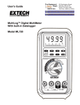
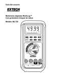
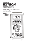
User’s Guide
MultiPro™ Digital MultiMeter Series
With PC Interface
Models:
MP510
MP520
MP530
1
WARRANTY
EXTECH INSTRUMENTS CORPORATION warrants this instrument to be free of defects
in parts and workmanship for three years from date of shipment (a six month limited
warranty applies on sensors and cables). If it should become necessary to return the
instrument for service during or beyond the warranty period, contact the Customer Service
Department at (781) 890-7440 ext. 210 for authorization. A Return Authorization (RA)
number must be issued before any product is returned to Extech. The sender is
responsible for shipping charges, freight, insurance and proper packaging to prevent
damage in transit. This warranty does not apply to defects resulting from action of the
user such as misuse, improper wiring, operation outside of specification, improper
maintenance or repair, or unauthorized modification. Extech specifically disclaims any
implied warranties or merchantability or fitness for a specific purpose and will not be liable
for any direct, indirect, incidental or consequential damages. Extech's total liability is
limited to repair or replacement of the product. The warranty set forth above is inclusive
and no other warranty, whether written or oral, is expressed or implied.
REPAIR AND CALIBRATION SERVICES
Extech offers complete repair and calibration services for all of the
products we sell. For periodic calibration, NIST certification or repair of
any Extech product, call customer service for details on services
available. Extech recommends that calibration be performed on an annual
basis to insure calibration integrity.
Support Hotline (781) 890-7440
Tech support: Ext. 200; Email: [email protected]
Repair/Returns: Ext. 210; Email: [email protected]
Website: www.extech.com
Copyright © 2002 Extech Instruments Corporation.
All rights reserved including the right of reproduction in whole or in part in any form.
MP Series V2.2 9/03
P/N: 7M1C-0241-A000
Introduction
2
Congratulations on your purchase of Extech model MP510, MP520, or
MP530 digital multimeter. Properly used, this meter will provide many
years of reliable service.
MultiPro™ Meters measure AC/DC Voltage, AC/DC Current, Resistance,
Frequency, Capacitance, Diode, and Continuity. The MultiPro™ also
offers RS-232 PC Interface data acquisition capabilities as an option.
Models MP520 and MP530 are True RMS AC sensing. In addition, the
MP530 offers Temperature, Relative, Peak capture and MIN/MAX
functions.
Safety
International Safety Symbols
This symbol, adjacent to another symbol or terminal, indicates
the user must refer to the manual for further information.
This symbol, adjacent to a terminal, indicates that, under normal
use, hazardous voltages may be present
Double insulation
Safety Precautions
1. Improper use of this meter can cause damage, shock, injury or death.
Read and understand this users manual before operating the meter.
2. Make sure any covers or battery doors are properly closed and
secured.
3. Always remove the test leads before replacing the battery or fuses.
4. Inspect the condition of the test leads and the meter itself for any
damage before operating the meter. Repair or replace any damage
before use.
5. Do not exceed the maximum rated input limits.
6. Use great care when making measurements if the voltages are
greater than 25VAC rms or 35VDC. These voltages are considered a
shock hazard.
7. Always discharge capacitors and remove power from the device
under test before performing Capacitance, Diode, Resistance or
Continuity tests.
3
8. Remove the battery from the meter if the meter is to be stored for
long periods.
9. To avoid electric shock, do not measure AC current on any circuit
whose voltage exceeds 500V AC.
10. Voltage checks on electrical outlets can be difficult and misleading
because of the uncertainty of connection to the electrical contacts.
Other means should be used to ensure that the terminals are not
"live".
11. The product is intended only for indoor use
12. If the equipment is used in a manner not specified by the
manufacturer, the protection provided by the equipment may be
impaired.
13. Pollution degree: 2
PER IEC1010 OVERVOLTAGE INSTALLATION CATEGORY
OVERVOLTAGE CATEGORY I
Equipment of OVERVOLTAGE CATEGORY I is equipment for
connection to circuits in which measures are taken to limit the transient
overvoltages to an appropriate low level. Note – Examples include
protected electronic circuits.
OVERVOLTAGE CATEGORY II
Equipment of OVERVOLTAGE CATEGORY II is energy-consuming
equipment to be supplied from the fixed installation.
Note – Examples include household, office, and laboratory appliances.
OVERVOLTAGE CATEGORY III
Equipment of OVERVOLTAGE CATEGORY III is equipment in fixed
installations.
Note – Examples include switches in the fixed installation and some
equipment for industrial use with permanent connection to the fixed
installation.
OVERVOLTAGE CATEGORY IV
Equipment of OVERVOLTAGE CATEGORY IV is for use at the origin of
the installation.
Note – Examples include electricity meters and primary over-current
protection equipment
Specifications
4
DC VOLTAGE
RANGE
Accuracy
50.00 mV
0.12% + 2d
500.0 mV
0.06% + 2d
5.000V, 50.00V, 500.0V, 1000V
0.08% + 2d
NMRR: >60dB @ 50/60Hz, CMRR: >120dB @ DC, 50/60Hz, Rs=1kΩ
Input impedance: 10MΩ, 16pF nominal (44pF nominal for 50mV & 500mV
ranges)
AC VOLTAGE
RANGE
Accuracy
50Hz/60Hz
50.00mV, 500.0mV, 5.000V, 50.00V, 500.0V, 1000V 0.5% + 3d
40Hz to 500Hz
50.00mV, 500.0mV
0.8% + 3d
5.000V, 50.00V, 500.0V
1.0% + 4d
1000V
1.2% + 4d
Up to 20kHz
50.00mV, 500.0mV
0.5dB*
5.000V, 50.00V, 500.0V
3dB*
1000V
Unspecified
*Specified from 30% to 100% of range
CMRR: >60dB @ DC to 60Hz, Rs=1kΩ
Input Impedance: 10MΩ, 16pF nominal (44pF nominal for 50mV &
500mV ranges)
DC CURRENT
RANGE
Accuracy
Burden Voltage
500.0µA, 5000µA
0.15mV/µA
0.2% + 4d
50.00mA, 500.0mA
3.3mV/mA
5.000A, 10.00A*
0.03V/A
*10A continuous, 20A for 30 seconds max with a 5 minute cool down
interval
AC CURRENT
RANGE
Accuracy
Burden Voltage
50 / 60Hz
0.6%+3d
500.0µA, 5000µA
0.15mV/µA
50.00mA, 500.0mA
0.6%+3d
3.3mV/mA
5.000A, 10.00A*
0.6%+3d
0.03V/A
40Hz to 1kHz
0.8%+4d
500.0µA, 5000µA
0.15mV/µA
50.00mA
0.8%+4d
3.3mV/mA
500.0mA
1.0%+4d
3.3mV/mA
5.000A, 10.00A*
0.8%+4d
0.03V/A
*10A continuous, 20A for 30-second max with 5 minutes cool down
interval
Peak Capture (for V & A)
Specified accuracy ±150 digits for changes > 5 ms in duration
TEMPERATURE (MP530 ONLY)
RANGE
Accuracy
0.3% + 3d
-50°C TO 1000°C
0.3% + 6d
-58°F TO 1832°F
RESISTANCE
RANGE
Accuracy
0.2% + 6d
50.00Ω
0.1% + 3d
500.0Ω
0.1% + 2d
5.000kΩ, 50.00kΩ, 500.0kΩ
0.4% + 3d
5.000MΩ
1.5% + 5d
50.00MΩ
Open Circuit Voltage: < 1.3VDC (< 3VDC for 50Ω & 500Ω ranges)
CAPACITANCE
RANGE
Accuracy*
50.00nF, 500.0nF
0.8% + 3d
1.0% + 3d
5.000µF
2.0% + 3d
50.00µF
3.5% + 5d
500.0µF
5.0% + 5d
9999µF
*Accuracies with film capacitor or better
5
FREQUENCY
Function
6
Sensitivity
(ACrms)
300mV
2V
20V
80V
300V
300mV
10% F.S.
Range
mV
10Hz - 125kHz
5V
10Hz - 125kHz
50V
10Hz - 20kHz
500V
10Hz - 1kHz
1000V
10Hz - 1kHz
10Hz - 125kHz
Ω, Cx, diode
10Hz - 125kHz
µA, mA, A
Accuracy: 0.01% + 2d
Audible Continuity:
Measurement threshold: Beeper will sound if measurement is below
20Ω. Beeper will not sound if measurement is above 200Ω. Beeper
may or may not sound if measurement is between 20 and 200Ω.
Response time: < 100µs
Accuracy Notes: Accuracy is ± (% reading digits + number of digits), or
as otherwise specified, at 23°C ±5°C < 75% R.H. True RMS accuracies
are specified from 5% to 100% of range or as otherwise specified.
Maximum Crest Factor <3:1 at full scale & <6:1 at half scale (with
frequency component within the specified frequency bandwidth for nonsinusoidal waveforms).
Digital Display:
5000-count LCD display; 5 per second nominal
refresh rate
Bar Graph Display:
52-segment bargraph; 60 per second nominal
refresh rate
Low Battery:
Below approx. 7V
Operating Temperature: 41° to 104°F (5° to 40°C)
Storage Temperature: -4° to 140°F (-20 to 60oC
Relative Humidity:
Max 80% up to 87ºF (31ºC) decreasing linearly
to 50% at 104ºF(40ºC): <80% storage
Altitude:
Operating below 2000 meters
Temp. Coefficient:
Nominal 0.15 x specified accuracy per ºC
(between 0 and 18oC or 28 to 50oC), or as
otherwise specified
Power Supply:
9V battery (NEDA1604, JIS006P or IEC6F22)
7
AC Sensing:
True RMS on MP520 and MP530
Auto Power Off: After 17 minutes of inactivity with no input signal
Safety:
The MultiPro™ Series meters are intended for indoor use
and protected, against the users, by double insulation per
EN61010-1 and IEC61010-1 2nd Edition (2001) to CAT III
1000V & CAT IV 600V. The meter (all versions) also
meets UL3111-1(1994)* and CSA C22.2 No. 1010-1-92*
to CAT III 1000V.
Terminals (to COM) ratings:
V:
CATEGORY III 1000 VOLTS AC & DC, AND
CATEGORY IV* 600 VOLTS AC & DC.
A / MAµA : CATEGORY III AND CATEGORY IV* 500
VOLTS AC AND 300 VOLTS DC.
*Category IV safety standard (for DMMs) was first released in
IEC61010-1 2nd Edition in year 2001, and was yet an UL published
standard at the time this manual was written.
UL Certification: The meter that bears the UL markings, if any, has
been investigated by UL headquarter in the USA per
UL standard UL3111-1 1st Ed to its highest CAT III
rating and international standard IEC61010-1 Second
Edition (year 2001) to CAT IV rating. The UL
markings on the meter, where applicable, are marked
as “UL Listed Cat III only” and “UL Classified to
IEC61010-1 2nd Ed. Cat IV”.
E.M.C.:
Meets EN61326(1997, 1998/A1), EN61000-4-2(1995) and
EN61000-4-3(1996). Also meets former standards EN55011
(1991) and EN50082-1(1997)
In an RF field of 3V/m: Capacitance function is not specified
Other function ranges: Total Accuracy = Specified Accuracy +
30 digits. Performance above 3V/m is not specified
Overload Protection:
µA/mA Range:
0.63/500V, IR 200kA, F fuse.
12.5A/500V IR 20kA, F fuse.
A Range:
1050V rms, 1450V peak
V Range:
mV, Ω and other: 600VDC/VAC rms
Power Consumption: 2.7 mA typical
Dimension: 7.32 x 3.43 x 1.4" with holster (186mm x 87mm x 35.5mm)
Weight:
15.17 oz. with holster (430g)
Meter Description (MP530 Shown)
8
1. 5000 count Liquid Crystal display
2. Function push-buttons
3. Rotary function switch
4. 10A input jack
5. V/Hz/Ω/Cap/Temp input jack
6. COM input jack
7. mA/uA current input jack
NOTE: RS-232 Optical interface is located
on the top rear of the meter.
Features
Analog Bargraph display
Visual indication of measurement in the tradition of an analog meter
pointer. The bargraph consists of 52 discrete viewing segments. The
bargraph is useful for detecting faulty contacts, identifying
potentiometer gradations, and viewing signal spikes.
True RMS vs. Average Sensing (AC Measurements)
True RMS meters can accurately measure non-sinusoidal waveforms,
as well as distorted sine waves that contain harmonics. Average
Sensing is a fast, accurate and cost effective method of measuring
pure sine wave signals. However, non-sinusoidal waveforms cannot
accurately be measured using Average-sensing techniques.
NOTE: The MP510 is average sensing; the MP520 and MP530 are
True RMS.
Backlit display
The MultiPro™ series multimeters are equipped with a backlight for
viewing the LCD display in poorly lit areas.
9
Data Hold
The HOLD function freezes the reading on the display for later
viewing.
Manual and Automatic Ranging
The MultiPro™ series multimeters are Autoranging, with manual
override.
Smart Power Auto Power Off
Smart Power shuts the meter down automatically after approximately
17 minutes of inactivity.
Audible Beeper
To disable the audible meter tones, press and hold the Hz key while
powering the meter.
Automatic Test Lead Resistance Compensation
Automatically compensates for the resistance of the test leads, as well
as the internal protection circuitry automatically, ensuring greater
accuracy of low resistance measurements.
MAX/MIN mode (MP530 only)
MAX/MIN mode stores the minimum and maximum readings in
memory for later viewing.
Relative mode (MP530 only)
Relative mode allows the meter to display the difference between the
actual measurement and a stored reference value.
Zoom mode analog pointer (MP530 only)
The Zoom mode magnifies the regular analog bar graph resolution (up
to 5 times) to show small signal changes
PeakC capture mode (MP530 only)
PeakC captures voltage or current signal that have durations as short
as 5ms. This mode is available in DCV, ACV, DCA, & ACA functions.
Operation
10
Measurement Considerations
NOTICE: Read and understand all warning and caution statements
listed in the safety section of this operation manual prior to using this
meter.
1. Always move the rotary function switch to the OFF position when the
meter is not in use. This meter has Auto Power OFF that
automatically shuts the meter OFF if 17 minutes elapse without
activity.
2. If "OL" appears on the display during a measurement, the
measurement exceeds the range selected. Change to a higher range.
AC/DC Voltage Measurements
1. Insert the black test lead into the negative COM jack and the red test
lead into the positive V jack.
2. Set the function switch to the "VAC" "VDC" "mV" position. Press the
SELECT key momentarily to toggle between AC and DC.
3. Read the voltage measurement on the display
AC/DC Current Measurements
CAUTION: Do not make current measurements at 20A for longer than
30 seconds. Exceeding 30 seconds may cause damage to the meter
and/or the test leads.
1. Insert the black test lead into the negative COM jack.
2. For current measurements up to 4000µA, set the function switch to
the "µA" position and insert the red test lead into the mA-µA jack.
3. For current measurements up to 400mA, set the function switch to the
"mA" position and insert the red test lead into the mA-µA jack.
4. For current measurements up to 10A, set the function switch to the
"A" position and insert the red test lead into the A jack.
5. Press the SELECT key momentarily to toggle between AC and DC.
6. Remove power from the circuit under test and open the circuit at the
point where you wish to measure current.
7. Touch the black test probe tip to the negative side of the circuit and
touch the red test probe tip to the positive side of the circuit.
8. Apply power to the circuit.
9. Read the current on the display
11
Resistance and Continuity Measurements
1. Insert the black test lead banana plug into the negative COM jack and
the red test lead banana plug into the V/Ω/CAP jack.
2. Set the function switch to the "Ω " position.
3. Press the SELECT key momentarily to select Continuity (if required).
4. Touch the test probe tips across the circuit or part under test. It is best
to disconnect one side of the part under test so the rest of the circuit
will not interfere with the resistance reading.
5. For Resistance tests, read the resistance on the display.
6. For Continuity tests, If the resistance is < 20Ω, an audible tone will
sound
Automatic test lead resistance calibration
When manually entering the 50Ω range (using the RANGE key) the
automatic test lead resistance feature will prompt ("Shrt" in the display)
the user to short the inputs for calibration. Short the test leads for about
3 seconds until the display shows zero. The resistance of the test leads
is now subtracted from the reading. The compensation value can be as
much as 5Ω.
Note: The compensation procedure must be repeated each time the
range or function is changed.
Capacitance Measurements
1. Insert the black lead into the negative COM jack and the red test lead
into the positive CAP jack.
2. Set the function switch to the " CAP" position.
3. Press the SELECT key momentarily to select Capacitance (if
required).
4. Touch the test leads to the capacitor to be tested and read the
measured value.
12
Frequency Measurements
1. Connect and make the measurement required as described in the
previous paragraphs.
2. Press the Hz key to select the Frequency (Hz) function.
3. Read the frequency on the display
Notes on sensitivity:
Input sensitivity varies automatically with function range selected. The
mV function has the highest (300mV) and the 1000V range has the
lowest (300V) sensitivity. It is recommended that the user first
measure the signal voltage (or current) level before activating the Hz
function to automatically set the most appropriate trigger level. You
can also press the RANGE button momentarily to select another
trigger level manually. If the Hz reading becomes unstable, select a
lower sensitivity to avoid electrical noise. If the display is zero, select
a higher sensitivity.
Diode Test
1. Insert the black lead into the negative COM jack and the red test lead
into the positive jack
2. Set the function switch to " CAP" position.
3. Press the SELECT key momentarily to select the diode function (if
required).
4. Touch the test probe tips to the diode or semiconductor junction you
wish to test. Note the meter reading.
5. Reverse the test lead polarity by reversing the red and black leads.
Note this reading.
6. The diode or junction can be evaluated as follows:
A. If one reading displays a value and the other reading displays "OL",
the diode is good.
B. If both readings display "OL", the device is open.
C. If both readings are very small or 0, the device is shorted.
Temperature Measurements (MP530 only)
1. Insert the Temperature Probe into the COM and TEMP input jacks
observing polarity.
2. Set the function switch to the "TEMP" position.
3. Use the SELECT key to toggle between oC and oF.
4. Touch the Temperature Probe tip to the device under test.
5. Wait 30 seconds for the measurement to stabilize then read the
display.
13
MAX/MIN (MP530 only)
1. Press the MAX/MIN key to activate the MAX/MIN recording mode.
The display annunciators "MAX/MIN" will appear. The meter will beep
every time a new maximum or minimum reading is sensed. Auto
power off is disabled while in MAX/MIN mode.
2. Press the MAX/MIN key to cycle through the stored MAX (maximum),
MIN (minimum) and MAX-MIN (maximum minus minimum) readings.
3. To exit MAX/MIN mode press and hold the MAX/MIN key for 2
seconds.
Relative mode (MP530 only)
1. Press the
key once to a store the displayed reading as the
reference value. The display will now show readings relative to the
stored reference value. (display = reading - stored value)
2. Press the Relative key again to exit the Relative mode.
Peak C capture mode (MP530 only)
1. Press the Peak C key momentarily to activate Peak Mode, which
captures voltage or current signal durations as short as 5ms. This
mode is available in DCV, ACV, DCA, & ACA functions (the display
annunciators "C" & "MAX" appear). The Auto Power Off feature will
be disabled automatically in this mode.
2. The meter will beep whenever a new maximum or minimum reading is
detected.
3. Press the Peak key to cycle through the Maximum (MAX), Minimum
(MIN), and Maximum minus Minimum (MAX-MIN) readings.
4. Press the PEAK key for 1 second to exit PEAK capture mode.
Smart Power™ Auto Power Off
Smart Power™ shuts the meter down automatically after
approximately 17 minutes of inactivity. The 17-minute time period is
reset any time the rotary switch is moved or as long as a signal is
being fed into the meter is greater than 10% of the range. This
prevents auto powering off during long term tests. To wake the meter,
press the SELECT key or turn the meter off and on again.
Disabling Auto Power Off
Press the RANGE key while turning the meter on to disable the Auto
Power Off feature
Audible Beeper
The audible beeper can be disabled by pressing the Hz key while
turning the meter on.
RS-232 PC Interface
14
This instrument is equipped with an optically isolated interface port
(located on the rear of the meter). An optional WindowsTM software
(part no. SW800) and interface package is available for data
acquisition applications. This optional kit is required to connect the
meter to a PC. The software provides digital, analog, and graphical
data displays. Refer to the README file in the interface kit for further
details.
Maintenance
WARNING
To avoid electrical shock, disconnect the meter from any circuit, remove
the test leads from the input jacks and turn OFF the meter before opening
the case. Do not operate with open case. Install only the same type of
fuse or equivalent
Cleaning and Storage
Periodically wipe the case with a damp cloth and mild detergent; do not
use abrasives or solvents. If the meter is not to be used for periods of
longer than 60 days, remove the battery and store it separately
15
Battery Replacement
Loosen the 2 screws from the battery access door of the case bottom. Lift
the battery access door and thus the battery compartment up. Replace
the battery. Re-fasten the screws.
Battery: Standard 9V Alkaline (NEDA1604, JIS006P, IEC6F22)
Fuse Replacement
1. Remove the four screws from the case bottom and stand using a
Philips head screwdriver.
2. Lift the end of the case bottom nearest the input jacks until it unsnaps
from the case top
3. Replace the battery or blown fuse(s)
4. Replace the case bottom, and ensure that all the gaskets are properly
seated and that the two snaps on the case top (near the display side)
are engaged
5. Re-fasten the screws.
Fuses:
FS1 (µA/mA Range): 0.5/0.63 ampere F, fast acting ceramic.
Preferred: Ferraz C084205 (0.63A)
Acceptable: Bussmann ABC-1/2 (0.5A)
FS2 (A Range): 12 ampere F, fast acting ceramic.
Preferred: Ferraz D085448 (12.5A)
Acceptable: Bussmann ABC-12 (12A)
A fuse kit, Extech P/N FS880, is available that contains one each of the
Ferraz fuses.