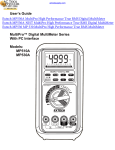
1
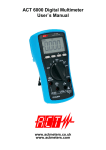
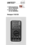
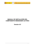
Operating Instructions
ACT720
True RMS Datalogging Multimeter
0.000
AUTO
~
O
2
1
3
V
4
5
MultiLog 72O True RMS
▼
RANGE
Hz
=
▼
AC/DC
SELECT
HOLD
AUTO POWER OFF
Ω
Temp
A
mA
CAP
►
µA
mV
OFF
VDC
◄
VAC
OFF
1OA
1OA µA
MAX
1OA
FUSED
MAX O.5A
FUSED
COM
V.TEMP
Ω.CAP
CATIV 6OOV
CAT III 1OOOV
Using high end technology, the ACT 720 combines a wide range of
measurements with datalogging capabilities to help the engineer
monitor and locate faults – fast.
www.actmeters.com
+44(0)1744 886660
ACT 720
Important Information
The ACT 720 measures AC/DC voltage and current, resistance,
frequency, capacitance, temperature, diode and continuity. The ACT
720 offers a built-in datalogger and an optical RS-232 interface. The
meter stores 43,000 data points in internal memory.
Safety
International Safety Symbols
!
▼
This symbol, adjacent to another symbol or terminal,
indicates the user must refer to the manual for further
information
This symbol, adjacent to a terminal, indicates that, under
normal use, hazardous voltages may be present
Double insulation
www.actmeters.com
+44(0)1744 886660
ACT 720
Important Information
1.
Improper use of this meter can cause damage, shock, injury or death. Read and
understand this user manual before operating the meter.
2.
Make sure any covers or battery doors are properly closed and secured.
3.
Always remove the test leads before replacing the battery or fuses.
4.
Inspect the condition of the test leads and the meter itself for any damage before
operating the meter. Repair or replace any damage before use.
5.
Do not exceed the maximum rated input limits.
6.
Use great care when making measurements if the voltages are greater than 25VAC
rms or 35VDC. These voltages are considered a shock hazard.
7.
Always discharge capacitors and remove power from the device under test before
performing capacitance, diode, resistance or continuity tests.
8.
Remove the battery from the meter if the meter is to be stored for long periods.
9.
To avoid electric shock, do not measure AC current on any circuit whose voltage
exceeds 500V AC.
10. Voltage checks on electrical outlets can be difficult and misleading because of the
uncertainty of connection to the electrical contacts. Other means should be used to
ensure that the terminals are not ‘live’.
11. The product is intended only for indoor use
12. If the equipment is used in a manner not specified by the manufacturer, the
protection provided by the equipment may be impaired.
13. Pollution degree: 2
www.actmeters.com
+44(0)1744 886660
ACT 720
Important Information
important
PER IEC1010 OVERVOLTAGE INSTALLATION CATEGORY
OVERVOLTAGE CATEGORY I
Equipment of OVERVOLTAGE CATEGORY I is equipment for connection to circuits in which
measures are taken to limit the transient overvoltages to an appropriate low level. Note examples include protected electronic circuits.
OVERVOLTAGE CATEGORY II
Equipment of OVERVOLTAGE CATEGORY II is energy-consuming equipment to be supplied
from the fixed installation. Note - examples include household, office and laboratory
appliances.
OVERVOLTAGE CATEGORY III
Equipment of OVERVOLTAGE CATEGORY III is equipment in fixed installations. Note examples include switches in the fixed installation and some equipment for industrial use
with permanent connection to the fixed installation.
OVERVOLTAGE CATEGORY IV
Equipment of OVERVOLTAGE CATEGORY IV is for use at the origin of the installation. Note
- examples include electricity meters and primary over-current protection equipment
www.actmeters.com
+44(0)1744 886660
ACT 720
Specifications
DC VOLTAGE
Range
Accuracy
50.00 mV
0.12% + 2d
500.0 mV
0.06% + 2d
5.000V, 50.00V, 500.0V, 1000V
0.08% + 2d
NMRR: >60dB @ 50/60Hz, CMRR: > 120dB @ DC, 50/60Hz, Rs+1kΩ
Input impedance: 10MΩ, 16pF nominal (44pF nominal for 50mV & 500mV ranges)
AC VOLTAGE
Range
50Hz/60Hz
50.00mV, 500.0mV, 5.000V, 50.00V, 500.0V, 1000V
0.5% + 3d
40Hz to 500Hz
50.00mV, 500.0mV
0.8% + 3d
5.000V, 50.00V, 500.0V
1.0% + 4d
1000V
1.2% + 4d
Up to 20kHz
50.00mV, 500.0mV
0.5dB*
5.000V, 50.00V, 500.0V
3db
1000V
Unspecified
* Specified from 30% to 100% of range
CMRR: >60dB @ DC to 60Hz, Rs+1kΩ
Input Impedance: 10MΩ, 16pF nominal (44pF nominal for 50mV & 500mV ranges)
DC CURRENT
Range
Accuracy
Burden Voltage
500.0µA, 5000µA
0.2% + 4d
0.15mV/µA
50.00mA, 500.0mA
0.2% + 4d
3.3mV/mA
5.000A, 10.00A*
0.2% + 4d
0.03V/A
*10A continuous, 20A for 30 seconds max with a 5 minute cool down interval
www.actmeters.com
+44(0)1744 886660
ACT 720
AC CURRENT
Range
Accuracy
Burden Voltage
500.0µA, 5000µA
0.6% + 3d
0.15mV/µA
50.00mA, 500.0mA
0.6% + 3d
3.3mV/mA
5.000A, 10.00A*
0.6% + 3d
0.03V/A
500.0µA, 5000µA
0.8% + 4d
0.15mV/µA
50.00mA
0.8% + 4d
3.3mV/mA
500.0mA
1.0% + 4d
3.3mV/mA
5.000A, 10.00A*
0.8% + 4d
0.03V/A
50 / 60Hz
40Hz to 1kHz
*10A continuous, 20A for 30-second max with 5 minute cool down interval
TEMPERATURE
Range
Accuracy
-50°C to 1000°C
0.3% + 3d
-58°F to 1832°F
0.3% + 6d
RESISTANCE
Range
Accuracy
50.00Ω
0.2% + 6d
500.0Ω
0.1% + 3d
5.000kΩ, 50.00kΩ, 500.0kΩ
0.1% + 2d
5.000MΩ
0.4% + 3d
50.00MΩ
1.5% + 5d
Open Circuit Voltage: < 1.3VDC (< 3VDC for 50Ω & 500Ω ranges)
CAPACITANCE
Range
Accuracy*
50.00nF, 500.0nF
0.8% + 3d
5.00µF
1.0% + 3d
50.00µF
2.0% + 3d
500.0µF
3.5% + 5d
9999µF
5.0% + 5d
* Accuracies with film capacitor or better
www.actmeters.com
+44(0)1744 886660
ACT 720
FREQUENCY
Function
Sensitivity (ACrms)
Range
mV
300mV
10Hz - 125kHz
5V
2V
10Hz - 125kHz
50V
20V
10Hz - 20kHz
500V
80V
10Hz - 1kHz
1000V
300V
10Hz - 1kHz
Ω, Cx, diode
300mV
10Hz - 125kHz
µA, mA, A
10% F.S.
10Hz - 125kHz
Accuracy: 0.01% + 2d
Accuracy Notes: Accuracy is ± (% reading digits + number of digits), or as otherwise
specified, at 23ºC ±5ºC < 75% R.H. True RMS accuracies are specified from 5% to 100% of
range or as otherwise specified. Maximum Crest Factor <3:1 at full scale & <6:1 at half scale
(with frequency component within the specified frequency bandwidth for non-sinusoidal
waveforms).
Audible Continuity: Measurement threshold: Beeper will sound if measurement is below
20Ω. Beeper will not sound if measurement is above 200Ω. Beeper may or may not sound
if measurement is between 20 and 200Ω. Response time: <100µs
Digital Display:
5000 count LCD display; 5 per second nominal refresh rate
Bar Graph Display:
52 segment bargraph; 60 per second nominal refresh rate
Datalogging Capacity:
43000 points
Datalog Sample Rate:
0.05 (0.2 for ºC/ºF & Ω, 0.4 for Hz and 1 for C), 1, 20, 40, 60, 120, 240 & 480 seconds
Low Battery:
Below approx 7V
Operating Temperature:
32º to 113ºF (0º to 45ºC)
Storage Temperature:
-4º to 140ºF (-20 to 60ºC)
Relative Humidity:
Max 80% up to 87ºF (31ºC) descreasing linearly to 50% at 113ºF (45ºC) <80% storage
Altitude:
Operating below 2000 meters
www.actmeters.com
+44(0)1744 886660
ACT 720
Temp. Coefficient
Nominal 0.15 x specified accuracy per ºC (between 0 and 18ºC
or 28 to 50ºC), or as otherwise specified
Power Supply
9V battery (NEDA 1604, JIS006P or IEC6F22)
AC Sensing
True RMS
Auto Power Off
After 17 minutes or inactivity with no input signal
Safety
Intended for indoor use and protected by double insulation
per EN61010-1 and IEC61010-1 2nd Edition (2001) to CAT III 1000V & CAT IV 600V. The
meter also meets UL3111-1(1994)* and CSA C22.2 No. 1010-1-92* to CAT III 1000V.
Terminals (to COM) ratings:
V:
CATEGORY III 1000 VOLTS AC & DC, AND CATEGORY IV* 600 VOLTS AC & DC
A/MAµA: CATEGORY III AND CATEGORY IV* 500 VOLTS AC AND 300 VOLTS DC
*Category IV safety standard (for DMMs) was first released in IEC61010-1 2nd Edition in
year 2001, and was yet a UL published standard at the time this manual was written
UL Certification
Meters that bear the UL marking have been investigated by
UL headquarter in the USA per UL standard UL3111-1 1st Ed to its highest CAT III rating
and international standard IEC61010-1 Second Edition (year 2001) to CAT IV rating. The UL
markings as ‘UL Listed Cat III only’ and ‘UL Classified to IEC61010-1 2nd Ed. Car IV’
E.M.C.
Meets EN61326 (1997, 1998/A1), EN61000-4-2(1995) and
EN61000-4-3(1996). Also meets former standards EN55011 (1991) and EN50082-1 (1997).
In an RF field of 3V/m: capacitance function is not specified. Other function ranges: Total
Accuracy = specified accuracy + 30 digits. Performance > 3V/m is not specified
Overload Protection
µA/mA Range
0.63/500V, IR 200kA, F fuse
A Range
12.5A/500V IR 20kA, F fuse
V Range
1050V rms, 1450V peak
mV, Ω and other
600VDC/VAC rms
Power Consumption
2.7mA typical
Dimension
186mm x 87mm 35.5mm with holster
Weight
430g with holster
www.actmeters.com
+44(0)1744 886660
ACT 720
Meter Description
1.
5000 count liquid crystal display
2.
Function push buttons
3.
Rotary function switch
4.
10A input jack
5.
V/Hz/Ω/Cap/Temp input jack
6.
COM input jack
7.
mA/µA current input jack
8.
RS232 connector (rear)
0.000
AUTO
~
O
2
1
3
V
4
5
1
MultiLog 72O True RMS
▼
RANGE
Hz
=
▼
AC/DC
SELECT
8
HOLD
2
AUTO POWER OFF
Ω
Temp
A
mA
CAP
►
µA
mV
OFF
VDC
3
◄
VAC
4
7
6
5
OFF
1OA
1OA µA
MAX
1OA
FUSED
www.actmeters.com
+44(0)1744 886660
MAX O.5A
FUSED
COM
V.TEMP
Ω.CAP
CATIV 6OOV
CAT III 1OOOV
ACT 720
Features
Analog Bargraph Display
Visual indication of measurement in the tradition of an analog meter pointer. The bargraph
consists of 52 discrete viewing segments. The bargraph is useful for detecting faulty
contacts, identifying potentiometer graduations and viewing signal spikes.
True RMS v Average Sensing (AC Measurements)
True RMS meters can accurately measure non-sinusoidal waveforms, as well as distorted
sine waves that contain harmonics. Average sensing is a fast, accurate and cost effective
method of measuring pure sine wave signals. However, non-sinusoidal waveforms cannot
accurately be measured using average sensing techniques.
Backlit Display
The ACT 720 is equipped with a backlight for viewing the LCD display in poorly lit areas
Data Hold
The HOLD function freezes the reading on the display for later viewing
Manual and Automatic Ranging
The ACT 720 is autoranging with manual override
Smart Power Auto Power Off
Smart power shuts the meter down automatically after appromimately 17 minutes of
inactivity
Audible Beeper
To disable the audible meter tones, press and hold the Hz key while powering the meter
Automatic Test Lead Resistance Compensation
Automatically compensates for the resistance of the test leads, as well as the internal
protection circuitry, ensuring greater accuracy of low resistance measurements
Datalogging
The ACT 720 will store reading for review on the LCD display or download to a PC using the
supplied software
www.actmeters.com
+44(0)1744 886660
ACT 720
Measurement Considerations
NOTICE: Read and understand all WARNING and CAUTION statements listed in the safety
section of this operation manual prior to using this meter
1.
Always move the rotary function switch to the OFF position when the meter is not
in used. The meter has Auto Power OFF that automatically shuts the meter OFF if 17
minutes elapse without activity
2.
If ‘OL’ appears on the display during a measurement, the measurement exceeds the
range selected. Change to a higher range.
AC/DC Voltage Measurements
1.
Insert the black test lead into the negative COM jack and the red test lead into the
positive V jack
2.
Set the function switch to the ‘VAC’ ‘VDC’ ‘mV’ position. Press the SELECT key
momentarily to toggle between AC and DC
3.
Read the voltage measurement on the display
AC/DC Current Measurements
CAUTION: Do not make current measurements at 20A for longer than 30 seconds.
Exceeding 30 seconds may cause damage to the meter and/or the test leads.
1.
Insert the black test lead into the negative COM jack
2.
For current measurements up to 4000µ, set the function switch to the ‘µA’ position and
insert the red test lead into the mA-µA jack
3.
For current measurements up to 400mA, set the function switch to the ‘mA’ position
and insert the red test lead into the mA-µA jack
4.
For current measurements up to 10A, set the function switch to the ‘A’ position and
insert the red test lead into the A jack
5.
Press the SELECT key momentarily to toggle between AC and DC
6.
Remove power from the circuit under test and open the circuit at the point where you
wish to measure current
7.
Touch the black test probe tip to the negative side of the circuit and touch the red test
probe tip to the positive side of the circuit
8.
Apply power to the circuit
9.
Read the current on the display
www.actmeters.com
+44(0)1744 886660
ACT 720
Resistance and Continuity Measurements
1.
Insert the black test lead banana plug into the negative COM jack and the red test lead
banana plug into the V/Ω/CAP jack
2.
Set the function switch to the ‘Ω ‘ position
3.
Press the SELECT key momentarily to select Continuity (if required)
4.
Touch the test probe tips across the circuit or part under test. It is best to disconnect
one side of the part under test so the rest of the circuit will not interfere with the
resistance reading.
5.
For Resistance tests, read the resistance on the display
6.
For Continuity tests, if the resistance is < 20Ω, an audible tone will sound
Capacitance Measurements
1.
Insert the black lead into the negative COM jack and the red test lead into the positive
CAP jack
►
2.
Set the function switch to the ‘
3.
Press the SELECT key momentarily to select the Capacitance function ( if required)
CAP’ position
4.
Touch the test leads to the capacitor to be tested and read the measured value
www.actmeters.com
+44(0)1744 886660
ACT 720
Important Information
Frequency Measurements
1.
Connect and make the measurement required as described in the previous paragraphs
2.
Press the Hz key to select the Frequency (Hz) function
3.
Read the frequency on the display
Notes on Sensitivity
Input sensitivity varies automatically with function range selected. The mV function has the
highest (300mV) and the 1000V range has the lowest (300V) sensitivity. It is recommended
that the user first measure the signal voltage (or current) level before activating the Hz
function to automatically set the most appropriate trigger level. You can also press the
RANGE button momentarily to select another trigger level manually. If the Hz reading
becomes unstable, select a lower sensitivity to avoid electrical noise. If the display is zero,
select a higher sensitivity.
Diode Test
1.
Insert the black lead into the negative COM jack and the red test lead into the positive
jack
►
2.
Set the function to ‘
3.
Press the SELECT key momentarily to select the diode function (if required)
CAP’ position
4.
Touch the test probe tips to the diode or semiconductor junction you wish to test.
Note the meter reading.
5.
Reverse the test lead polarity by reversing the red and black leads. Note this reading.
6.
The diode or junction can be evaluated as follows:
A. If one reading displays a value and the other reading displays ‘OL’ the diode is good
B. If both readings display ‘OL’, the device is open
C. If both readings are very small or 0, the device is shorted
Temperature Measurements
1.
Insert the Temperature Probe into the COM and TEMP input jacks observing polarity
2.
Set the function switch to the ‘TEMP’ position
3.
Use the SELECT key to toggle between ºC and ºF
4.
Touch the Temperature Probe tip to the device under test
5.
Wait 30 seconds for the measurement to stabilize then read the display
www.actmeters.com
+44(0)1744 886660
ACT 720
Smart Power Auto Power Off
Smart Power shuts the meter down automatically after approximately 17 minutes of
inactivity. The 17 minute time period is reset any time the rotary switch is moved or as long
as the signal being fed into the meter is greater than 10% of the range. This prevents auto
powering off during long terms. To wake the meter, press the SELECT key or turn the meter
off and on again.
Audible Beeper
The audible beeper can be disabled by pressing the Hz key while turning the meter on.
www.actmeters.com
+44(0)1744 886660
ACT 720
Datalogging
Datalogging Basics
The ACT 720 can store up to 43,000 readings automatically. These readings can be viewed
on the LCD display or transferred to a PC using the PC interface cable and Windows
software included.
Datalogging
NOTE: Each time the datalogging ‘Strt’ process is initiated, existing data will be erased.
Always review or download stored data before beginning a new recording session.
1.
Press the
timer key to enter the sample rate mode. The default setting is 0.05
seconds
2.
Press the up/down arrow keys to select the desired sample rate
3.
Press the
4.
Press and hold the
timer key to store the selected sample rate
‘Strt, PAUS, StoP’ key for 1 second until ‘Strt’ appears in the
display to start the datalogging process
5.
The baragraph display will appear with a single oscillating pointer to indicate the
datalogging process is in progress
6.
Press the
‘Strt, PAUS, StoP’ key to pause datalogging. A blinking ‘H’ will appear in
the display
7.
Press
again to continue datalogging. ‘Cont’ will appear momentarily in the display
8.
Press the SELECT key to toggle between the measured value display and the data list
item number display
9.
Press and hold the
key for 1 second until ‘StoP’ appears in the display to stop the
data logging process and store the data
www.actmeters.com
+44(0)1744 886660
ACT 720
Recalling Stored Readings
To recall stored data, press the START, UP or DOWN arrow key momentarily to ‘CALL’ the
logged data. The LCD will show a flashing ‘C’ (CALL) to indicate that the data shown is logged
data. The data can also be transferred to a PC using the supplied Windows software and
interface cable. When the datalogger is paused or when the CALL mode is activated, select
from the following activities for datalog viewing:
1.
Use the arrow keys to scroll through the data on the meter’s LCD display
2.
Press and hold the UP or DOWN arrow keys to quickly scan the logged data. The meter
provides an audible tone when the first or last reading is reached
3.
Press the UP and DOWN arrow keys at the same time momentarily to display
alternately the MINIMUM and MAXIMUM readings
4.
Press the UP or DOWN arrow key momentarily while holding the HOLD key to search
all of the trends in the recorded data list. This LCD will indicate MIN or MAX for each
trend in the list.
Meter Memory Full
When the meter memory is full, the datalogging process ceases automatically and the
meter will enter the Auto Power OFF mode. Note that while datalogging, the Auto Power
OFF mode is disabled.
Low Battery Datalogging
If the 9V battery voltage falls critically low while the meter is datalogging, the meter
automatically ceases logging to ensure the integrity of the data recorded
Non-Volatile Data Storage
Data are stored in non-volatile memory shortly after each measurement is taken to
maximize data safely. However, the end-of-data information can only be stored after a
datalogging event is complete. Always ‘StoP’ the datalogger before switching off the meter.
www.actmeters.com
+44(0)1744 886660
ACT 720
Datalogging Sample Rate
Press the TIMER key momentarily to display the datalogger’s sampling rate (recording
interval). The factory default interval is 0.05 seconds, meaning that a reading will be logged
every 5 hundredths of a second. Press the UP and DOWN arrow key momentarily to select
an alternate sampling interval. Choose from 0.05 up to 480 seconds. Note that the fastest
sampling interval for Temperature and Resistance readings is 0.2 seconds: For Frequency
it is 0.4 seconds; and for Capacitance it is 1 second. Press the TIMER key again to confirm
the new setting.
The Sampling Rate cannot be changed while the meter is datalogging. When a Sampling
Rate of 20 seconds or longer is selected, the meter enters a standby state between readings
(to conserve battery life). While in stand-by, the bargraph will continue to operate. To wakeup meter from a stand-by state in order to view a real-time measurement, press the SELECT
key momentarily.
RS232C PC Computer Interface Capabilities
This device is equipped with an optical isolated interface port located on the rear of
the meter. The data acquisition package includes an interface cable and Windows data
acquisition software. The software provides in the format of a digital meter, a analog meter,
a comparator meter, and a graphical display. Refer to the README file on the software disk
for further details.
www.actmeters.com
+44(0)1744 886660
ACT 720
WARNING: To avoid electrical shock, disconnect the meter from any circuit, remove the test
leads from the input jacks and turn OFF the meter before opening the case. Do not operate
with open case. Install only the same type of fuse or equivalent.
Cleaning and Storage
Periodically wipe the case with a damp cloth and mild detergent; do not use abrasives
or solvents. If the meter is not to be used for periods of longer than 60 days, remove the
battery and store it separately.
UL Listed
The UL mark does not indicate that this product has been evaluated for the accuracy of its
readings.
www.actmeters.com
+44(0)1744 886660
ACT 720
Battery Replacement
Loosen the 2 screws from the battery access door of the case bottom. Lift the battery
access door and thus battery compartment up. Replace the battery. Refasten the screws.
Battery: Standard 9V Alkaline (NEDA 1604, JIS006P, IEC6F22)
Fuse Replacement
1.
Remove the four screws from the case bottom and stand using a Philips head
screwdriver
2.
Lift the end of the case bottom nearest the input jacks until it unsnaps from the case
top
3.
Replace the battery or blown fuses(s)
4.
Replace the case bottom, and ensure that all the gaskets are properly seated and that
the two snaps on the case top (near the display side) are engaged
5.
Refasten the screws
Fuses:
FS1 (µA/mA Range): 0.5/0.63 ampere F, fast acting ceramic
Preferred: Ferraz C084205 (0.63A)
Acceptable: Bussmann ABC-1/2 (0.5A)
FS2 (A Range): 12 ampere F, fast acting ceramic
Preferred: Ferraz D085448 (12.5A)
Acceptable: Bussmann ABC-12 (12A)
www.actmeters.com
+44(0)1744 886660