1
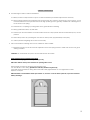
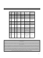
ET BLUE-ROLL
Domestic type roll-up garage door operator
Installation manual
Revision Oct.08.002
[email protected]
Technical specifications may change without prior notice.
All goods are subject to the standard factory warranty as laid out on the last page of this publication
G&C Electronics cc. T/A ET Systems
15 Nelson Rd, Observatory, Cape Town, South Africa
www.et.co.za
1
We strongly recommend that a set of safety infra red beams (ET BLUE I’s) be used for additional
protection.
DO NOT operate the Garage door operator while a person, especially a child is near the door.
Children must be under adult supervision at all times near an automated garage door especially
whilst the operator is in use.
Ensure that the BUILT IN SAFETY OBSTRUCTION SENSING SYSTEM (Load sensing) is correctly setup.
Regular testing (Monthly) is advised and adjustment must be made if necessary.
DO NOT pull the Manual release cord that changes the operator to manual operation whilst any
person or object is near or under the path of the door. If possible always change the operator to
manual mode with the door in the full closed position.
Connect the operator’s 220Vac mains cord to properly earthed mains. Installation and wiring must
comply with local council electrical code. (Enquire at your local municipality for a certified electrician
if uncertain)
DISCONNECT electrical power before undertaking any repairs to the garage door operator. Only
experienced professional personnel should remove the covers.
Keep hands and or other parts of the body, as well as loose items of clothing, clear of the door and
operator while operating or servicing.
In applications where “auto-close” is required, a set of safety infra red beams (ET BLUE I’s) MUST be
installed. The safety device must be tested regularly (Monthly) for correct operation. EXTREME
CAUTION is necessary when setting an operator to “auto-close” mode. Safety rules must be adhered
to at all times. Some regions SAFETY CODES OF PRACTICE disallow the use of “auto-close” in garage
door automation. If uncertain rather don’t make use of this feature, or investigate further.
The SAFETY OBSTRUCTION SENSING SYSTEM (Load sensing) is only activated when a certain level of
resistance (Resistive Force) is exerted onto both the door and object/person obstructing the travel. As
a result, the object/person may suffer a degree of DAMAGE or INJURY relative to the SAFETY REVERSE
SYSTEM (Load sensing) setting. It is strongly recommended that SAFETY INFRA RED BEAMS (ET BLUE I’s)
be installed to increase the safety level.
Ensure that the door is fully open before passing through the doorway and fully closed before leaving
the area.
Keep the door in CLEAR LINE OF SIGHT whenever operating.
2
PRE-INSTALLATION INSTRUCTIONS
1. PRE-INSTALLATION PREPARATION
1.1. Ensure sufficient side room space:
Minimum side room of 85mm from the face of the door drum wheel to the inside edge of the door support
bracket is required to install the opener (see Fig. 1) and maximum side room is 125mm before having to
move and re-fit the support bracket or install the drive unit fully inside the drum (Fig. 7)
1.2. Ensure reasonable door condition and operation:
Before beginning the installation of the opener, check the operation of the door. The door must be well
balanced and be in reasonable condition. In general, the door should stay unmoving at around 900mm
and 1200mm above the floor. The door should not stick or bind in the guide tracks. The ideal operational
effort in raising or lowering the door should not exceed a force of 15kgF.
Fig. 1
Fig. 2
3
INSTALLATION INSTRUCTIONS
WARNING: EXTREME CARE SHOULD BE TAKEN TO PREVENT ANY POSSIBLE DAMAGES
2.
INSTALLING THE OPENER ONTO THE DOOR SHAFT
There are various methods on how to install an opener to the door. The following is the most typical method.
CAUTION: THE INSTRUCTIONS SHOWN HERE ARE FOR RIGHT-HAND INSTALLATION
2.1 Roll the door up until the door curtain is out the door guides / tracks and use a rope to firmly tighten the roll in the
middle of the door (see Fig. 3).
2.2 Go to the opposite side of the door from where the opener is to be installed and ensure the U-bolts fastening the
door shaft to the bracket are firmly tightened. Pay extra attention here, otherwise the door shaft could loosen
when the U-bolt on the installation side is released.
2.3 Using a suitable prop, e.g. step ladder, together with soft padding to protect the door surface, support the door
on the right-hand side (see Fig. 3)
2.4 Loosen the nuts that secure the U-bolt on the right-hand side of the opener (opener installation side) and carefully
place the door onto the supporting prop. Remove and refit the door support bracket to a suitable side room
position, if required.
Fig. 3
4
2.5 Switch the opener into manual operation mode by pulling the manual release handle to enable the opener
drive to rotate freely.
2.6 Raise the door carefully, insert the opener into the door axle and ensure the two opener forks hold the door drum
wheel support. Push the opener inside the door roll as deep as possible (Fig. 4). In cases where the drum spokes
do not match the drive fork, fasten a block of wood or similar material to the drum that will hold firm when driven.
(Fig 6). Use washers to prevent the fasteners tearing out of the drum wheel.
Fig. 4
Fig. 5
2.7 Re-position the door shaft on the door support bracket and fit the specially supplied U-bolt (Fig. 5) over the axle /
drive assembly and tighten firmly.
2.7.1
In cases where the unit is installed where it can not be fastened to the door support bracket as in Fig.7,
the addition of a self drilling tech screw through the base of the clamp into the torsion bar, may be
necessary after clamping the U bolt to the torsion bar. This will prevent the motor drive unit slipping
around the torsion bar which will cause the limit positions to drift.
2.8 Remove the supporting prop, untie the rope and insert the door curtain back into its guides.
Fig. 7
Fig. 6
2.9 Manually open and close the door a few times to ensure the door runs freely and does not interfere with
unmoving parts of the opener. NB! Ensure the manual release cord is free from snagging and can be activated
easily. Care must be taken that the cord does not snag and become tangled in the drum as the door travels up
and down. Protect the cord from slicing and wear, if routed over the edge of the mounting bracket.
5
PIN DOOR CURTAIN TO DOOR DRUM WHEEL
3.1 Pinning the door curtain to the drum wheel will reduce possible forced lifting of the door.
Close the door to the fully closed position and mark the two positions where the curtain is to be pinned onto the
drum wheel on either side of the door. The marked positions (pinning locations) should be at least 90o apart (see
Fig. 8).
2.1 Raise door a little so that you can access the marked positions and pin curtain to drum wheel with self-drilling
tech screws or rivets.
Fig. 8
WEIGHT BARS (Optional – not supplied)
4.1 Weight bars may be required. Their main purpose is to eliminate the possibility of the door curtain ballooning on
initial start-up (from the door fully open position). After installing your new opener, if your door balloons on initial
start-up then we recommend that you fit one or two weight bars to the bottom edge of your door (total weight 57kg) as detailed below. (See Fig. 9).
4.2 Move the door manually to the mid-open position. If fitting one bar, centre it between either sides of the door. In
the case of two weight bars, fit them +/- 300 mm in from either side of the door. This ensures an even distribution
of the weight. Once the weight has been fitted the door should have a natural tendency to lightly freefall from
the mid-open position when in manual mode. The door should not drop rapidly!
Weight bar
Fig. 9
6
THE CONTROL UNIT.
Fig. 10
1
Light fitting
2
Light cover lens
3
Batteries
4
Control card
5
Transformer behind control card
6
Drive unit cable inlet
7
220V mains cable inlet
8
Antenna
9
Light cover lens fastening screw
10
Main control cover
11 Main control cover fastening screw
7
CONNECT THE DRIVE UNIT CABLE TO THE CONTROL CARD AS PER FIG. 12 OR FIG. 13 TO CONTINUE.
NB. The motor wiring of a right hand installation differs to that of a left hand installation! Figures 12 and 13
below indicate the wiring requirements for either left or right handed type installations.
Fig. 9
8
A
B
C
D
E
F
G
H
I
Autoclose jumper
On = active (20secs and pre-beep warning)
BT + centre = Button trigger function (25 users)
Receiver programming pins
LT + centre = Courtesy light function (6 users)
Receiver programming and detect LED
See table under receiver programming section below
Onboard test button
Functions as per transmitter BT
220Vac mains fuse
Replace with 2A fast blow type only
Increase (Anti-clockwise) or Decrease (Clockwise)
allowed resistance before safety reverse intitiates.
Load POT
Adjust for closing cycle. Open cycle is automatically
set.
This is preset in the factory to 27.2Vdc.
Charger float voltage POT
Peak current 370mA.
Replace with 8A fast blow type fuse only.
Motor power supply fuse.
If this fuse is blown the entire control card will be
without power.
On = Battery low beeps de-activated.
Battery low monitoring beep tone jumper
Off = Battery low beeps active. (Must be off when
batteries are installed)
For further detail on these features see page 11
The colouring of the factory fitted wiring is highlighted here
1.
2.
3.
4.
5.
6.
7.
8.
9.
10.
11.
12.
13.
14.
15.
16.
17.
18.
19.
20.
21.
22.
23.
N/O Safety beams input (BM)
N/O Courtesy light input (L)
Common output (C)
N/O Button trigger input (BT)
Green 0,3mm from motor head lead N/C Closed limit input (LC)
White 0,3mm from motor head lead Limit switch common output (C)
Brown 0,3mm from motor head lead N/C Open limit input (LO)
WHITE 220Vac Courtesy light output (LMP)
WHITE 220Vac Courtesy light output (LMP)
GREEN & YELLOW Motor and transformer earth (E)
GREEN & YELLOW Household earth (E)
BLUE 220Vac Neutral input (N)
BROWN 220Vac Live input (L)
BROWN 220Vac output to transformer primary (PRI)
BROWN 220Vac output to transformer primary (PRI)
Per Opener mounting 24Vdc motor output (MOT)
Per opener mounting 24Vdc motor output (MOT)
BLUE Battery negative (BAT)
RED Battery positive (+)
YELLOW 24Vac input from transformer secondary (SEC)
YELLOW 24Vac input from transformer secondary (SEC)
Positive auxiliary output (+ 12V, 100mA peak )
0V auxiliary output (Ground)
Fig. 11
9
Fig. 12
Left hand installation
Fig. 13
Red 0.75mm
Motor
Yellow 0.75mm
Motor
White 0.3mm Limit common
Brow n 0.3mm
Open limit
Green 0.3mm
Closed limit
Right hand installation
10
CONTROL CARD FEATURES AND SETUP EXPANDED
A.
Auto-close link: Placing a jumper across these 2 pins will cause the door to close automatically after 20sec. from any
open position. Before closing the unit will emit three warning beeps. The door can still be triggered to close manually
before 20sec. has counted down.
B.
Receiver programming pins: Max BT (Button trigger function) = 25 locations. Max L (Light function) = 6 locations.
To master erase: (It is recommended that this be done on first time set up)
1.
2.
3.
4.
5.
Remove all power.
Short middle and BT receiver pins and place a wire short between terminal 3 and 4 (C + BT ) of connector
block(or press and hold test button “D”)
Re-apply power. Buzzer will begin 1 second beeps.
When buzzer emits 1 continuous tone remove shorts and power.
Re-apply mains power first then battery power.
Programming new Transmitters into memory
1.
2.
3.
Press and hold required TX button.
While holding the TX button short the middle pin to the required function pin (BT or L)
When buzzer beeps release TX button and remove short.
1 x Beep - First TX in memory for that function.
2 x Beeps – There is still memory available for this function.
10 x Beeps – The last memory location for this function has been filled. Collect all TX’s used for this function
and check that they are all still working. The last TX learned into this function may have been erased to allow
your new TX.
4.
Repeat 1 to 3 above for further TX’s.
C.
RX detection L.E.D. This will flicker whenever there is a Keeloq transmission present on 433.92 MHz. Non Keeloq formats
will not activate this L.E.D. Also used as visual confirmation in programming of the onboard RX
D.
Test Button: Will operate door as though using a remote button.
E.
AC supply Fuse: If blown replace with a 2A fast blow fuse only. (Minimises control card damage in cases of power
surges or electrical spikes)
F.
Load sensing P.O.T: Used to adjust the amount of obstruction sensitivity necessary to initiate the automatic safety
routine. NB! The ET BLUE ROLL automatically sets its own opening load sensing off the closing setting. When adjusting
the load sensing use the closing direction!
When closing, the door will stop and reverse on sensing an obstruction. When opening the door will stop and wait
for the next trigger to reverse. Turn clockwise to make the operator less sensitive to obstructions. To test place a
40mm high object below the door when closing. On encountering the object door should return to the open
position without excessive strain to the door or obstruction object.
G.
Charger Voltage P.O.T: This has been set in the factory to 27 – 27.2 Volts without battery load. Do not adjust unless
qualified to do so. The peak effective current is limited to 370mA. This is a constant voltage, variable current charger
(Float stage/trickle charger)
11
H.
Motor output fuse: If blown replace with an 8A fast blow fuse only. This fuse will normally blow if the maximum resistive
load (Heavy door action/obstruction) is exceeded.
I.
Battery low beep override jumper: If the unit has been installed without batteries, place the jumper across the pins
here. The unit will no longer beep once every 16 seconds. NB! When batteries are installed the battery low beeps must
be active!
Advanced onboard receiver features.
7.1 Adding remotes via an existing remote: This feature allows the installer to guide the end user through the adding
of remote controls to the Bt (Button trigger) channel without accessing the control card, using a previously
programmed remote that has control of the L (light) function.
a.
b.
c.
d.
Open door fully,
Press and hold the remote button that controls the (L) light function, until the onboard buzzer emits a
continuous tone,
Press and release the required button on the new transmitter before the buzzer tone stops. If the tone
stops before pressing a transmitter button then restart from (b).
The onboard buzzer will indicate whether or not the programming was successful by one of the
following;
i.
No beeps = unsuccessful – contact supplier.
ii.
2 beeps = successful – repeat steps (a) to (c) for more remote programming.
iii.
10 beeps = successful however the previous remote in memory location has been deleted due
to the memory being full. – Contact supplier.
7.2 Remote controlled holiday lock-out: This feature allows for any of the remotes programmed into the L (light)
channel to lock-out all use of the unit. I.e. disallow housekeeper from gaining access when the owner is away.
7.2.1
7.2.2
Close door fully,
Press and hold the remote button that controls the L (light) function, until the onboard buzzer emits five
(5) rapid beeps.
Any Bt (Button trigger) attempt will now result in the onboard buzzer repeating the three rapid beeps.
7.2.3
To unlock repeat (b) above, this time however the onboard buzzer will emit four (4) long beeps to
indicate unlocking status. After the beep confirmation, normal use is again active.
12
Adjusting the open and closed limit positions:
Fig. 14
Fig. 15
Accessing the limit switches
Loosen the limit cams
Fig. 16
SETTING THE DOOR TRAVEL LIMITS.
A: RIGHT-HAND SIDE INSTALLATION.
Remove the back cover from the opener (Fig 14). Pull the manual release handle to change opener to the manual
operation mode.
8.1 Open Limit:
Raise the door manually to the open position you would like it to stop at. Slightly loosen the wing-nuts that lock
the cam (to the extent that you can rotate the cam by hand while the cam can not rotate itself). Rotate the
open limit cam (inner cam) clockwise by hand in the direction of the limit switch until the cam clicks the open
limit switch (see Fig. 16).
8.2 Closed Limit:
Close the door manually to a closed position so that the bottom edge of the door just touches the floor. Rotate
the closed limit cam (outer cam) by hand anti-clockwise until the cam clicks the closed limit switch (see Fig. 16).
13
8.3 Slightly re-tighten the two wing-nuts
8.4 Power controller up by connecting the mains power first and then the battery leads
8.5 Pull the manual release handle to change the opener back to automatic mode.
Testing and adjusting travel limit settings (RIGHT-HAND fit):
8.6 Close position:
Press and release the onboard test button. If the door does not stop at the pre-set closed position, repeat step 6.3
above. Turn the closed limit cam anti-clockwise to raise the closed position or clockwise to lower it. Tighten the
wing-nuts after the adjustment
8.7 Open position:
Press and release the onboard test button. If the door does not stop at the pre-set open position, repeat step 6.2
above. Turn the open limit cam anti-clockwise to raise the open position or clockwise to lower it. Tighten the wingnuts after the adjustment.
B: LEFT-HAND SIDE INSTALLATION.
Remove the back cover from the opener using a screwdriver. Pull the manual release handle to change opener to the
manual operation mode.
9.1 Open Limit:
Raise the door manually to the open position you would like it to stop at. Slightly loosen the wing-nuts that lock
the cam (to the extent that you can rotate the cam by hand while the cam can not rotate itself). Rotate the
open limit cam (inner cam) anti-clockwise by hand in the direction of the limit switch until the cam clicks the
open limit switch (see Fig. 16).
9.2 Closed Limit:
Close the door manually to a closed position so that the bottom edge of the door just touches the floor. Rotate
the closed limit cam (outer cam) by hand clockwise until the cam clicks the closed limit switch (see Fig. 16).
9.3 Slightly re-tighten the two wing-nuts
9.4 Power controller up by connecting the mains power first and then the battery leads
9.5 Pull the manual release handle to change the opener back to automatic mode.
Testing and adjusting travel limit settings (LEFT-HAND fit):
9.6 Close position:
Press and release the onboard test button. If the door does not stop at the pre-set closed position, repeat step 6.3
above. Turn the closed limit cam anti-clockwise to raise the closed position or clockwise to lower it. Tighten the
wing-nuts after the adjustment
9.7 Open position:
Press and release the onboard test button. If the door does not stop at the pre-set open position, repeat step 6.2
above. Turn the open limit cam anti-clockwise to raise the open position or clockwise to lower it. Tighten the wingnuts after the adjustment.
IMPORTANT NOTE: If the door stops on the down cycle and reverses on the up cycle, when encountering an
obstruction/binding, then the motor wires are connected incorrectly and must be reversed
14
GENERAL MAINTENANCE:
10 The following should be conducted MONTHLY
10.1 Safety reverse test. Repeat the test (see F control card features) and make adjustments if necessary.
10.2 Door manual operation test. Manually open and close the door. Check to ensure door is not too heavy or over
tensioned, difficult to close (should be less than 15kg operating force in general), unbalanced or binding due to
loss of tension in the spring.
10.3 Check door is not pulling or pushing askew in the guide tracks thus binding.
10.4 Keep guide tracks clean, dry and clear.
10.5 Check open and closed limits. Check and make sure door is fully opened and closed at desired open / closed
positions.
10.6 Test battery reserve by operating the door with no mains power. (Approximately 5 full cycles)
10.7 Call for professional garage door service if necessary.
11 We recommend the following service to be carried out ONCE A YEAR:
11.1 Professional services to the door and re-adjustment of the door spring tension to make sure the door is in good
working condition.
CAUTION: Do not lubricate the opener. Do not lubricate the door tracks.
HOW TO REPLACE THE COURTESY LIGHT BULB.
Use non inductive (tungsten filament) 40watt type only
NB! Switch 220Vac mains power off whenever opening either cover!
Remove light cover/lens by removing the fastening screw.
Turn fused bulb out of its fitting. (Beware the bulb may still be hot if just fused)
Insert and screw new bulb into fitting. Ensure the bulb is firmly tightened but not over tightened in socket.
Replace cover/lens
NB! Remember to switch 220Vac mains power back on, once the cover has been replaced, to prevent unwanted
battery discharge.
15
ET BLUE ROLL Beeps schedule and trouble shooting guide.
Beeps
Door
position
1
Anywhere
2
Closed
220V
Battery
mains charged/dison/off
charged
On
Off
Door Action
Status
Command used
to cause beep/s
On
None
Initial power up
Power applied
Charged
Door will
open
after beeps
Mains failure
BT triggered
Autoclose active
and
door is about to
close
Autoclose or
BT triggered
3
Open
Either
Either
Door will
close
after beeps
4
Closed
Either
Either
None
Holiday lock out
"unlocking"
confirmation
Courtesy light
button
held for >10 sec.
None
Holiday lock out
"locking or locked"
confirmation
Courtesy light
button
held for >10 sec.
Or BT triggered
None
Battery charge
level
is less than
minimum allowed
BT triggered
Will operate
Battery charge
level is less than
minimum allowed
and busy
charging
None
5
Rapid
15
Once
every
16sec.
Closed
Anywhere
Anywhere
Either
Off
On
Either
Dis-charged
Charging
In case of any misunderstanding of the beep tones contact your nearest ET Branch product support centre
for assistance.
These beeps are important warnings to help prevent damage to the unit. Your client should be instructed on
the use of them.
When contacting any of our support centres please have a record of any beep activity. This will assist in the
accurate diagnostic of the fault and assist us in maintaining our high expectancy of support for our products.
You may be asked to take readings with a multi-meter. Please have one handy. If you are not proficient in
the use of a multi-meter please contact a service provider in your area. Your nearest ET Systems branch will
have contact details of preferred service providers in your area.
16
WARRANTY: All goods manufactured by G&C Electronics cc T/A ET Systems carry a 12 month factory warranty from date
of invoice. All goods are warranted to be free of faulty components and manufacturing defects. Faulty goods will be
repaired or replaced at the sole discretion of ET Systems free of charge. This warranty is subject to the goods being
returned to the premises of ET Systems. The carriage of goods is for the customers account. This warranty is only valid if the
correct installation and application of goods, as laid out in the applicable documentation accompanying said goods, is
adhered to. All warranty claims must be accompanied by the original invoice. All claims made by the end user must be
directed to their respective service provider/installer.
The following items are not included in the warranty.
•
The light globe
•
The batteries
•
Motor brush wear
•
Acceptable wear and tear.
The following conditions will disqualify this product from the warranty as laid out above.
These conditions are non-negotiable.
•
Any single ET BLUE ROLL garage door operator used to automate more than one door at one time.
•
Any ET BLUE ROLL garage door operator used outdoors, including carports or non weatherproof
environments.
•
Any ET BLUE ROLL domestic garage door operator used in excessive traffic applications for example an
apartment-block parking garage.
•
Any unauthorised non-manufacturer modifications to the product or components thereof.
17