1
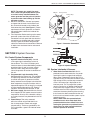
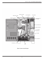
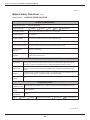
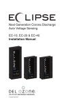
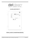
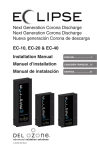
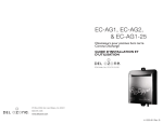
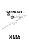
HECD HECD–65 & HECD–130 Installation & Operations Manual 3580 Sueldo Street, San Luis Obispo, CA 93401 | 800.676.1335 | [email protected] | www.delozone.com 4-0696 Rev.D HECD–65 & HECD–130 Installation & Operations Manual TABLE OF CONTENTS SECTION 1 General Information 1A. Description................................................................2 1B. Specifications............................................................2 1C. Standard Features....................................................2 1D. Accessories & Optional Equipment...........................2 1E. Warranty Summary...................................................2 SECTION 2 Installation Installation.......................................................................2 SECTION 3 System Overview 3A. Control System Components....................................3 3B. System Interlocks & Sensors....................................3 3C. High Voltage Power Supply......................................4 3D. Corona Discharge (CD) Modules..............................4 3E. Air Preparation & Oxygen Control.............................6 3F. Operator Interface Panel...........................................6 SECTION 4 Operation 4A. System Start-Up........................................................7 4B. Cooling Water...........................................................7 4C. Feed Gas Flow System Preparation.........................7 4D. External Controllers..................................................8 4E. Ozone Generator Start-Up........................................8 4F. System Shut-Down....................................................8 SECTION 5 Maintenance & Service 5A. Preventive Maintenance Schedule.......................... 8 5B. Corona Discharge (CD) Module Service.................. 9 5C. Power Supply Service............................................ 10 5D. Air Compressor Service......................................... 10 5E. Service Interval Timers........................................... 10 SECTION 6 Replacement Parts & Order Info 6A. Ordering Information...............................................11 SECTION 7 Troubleshooting Troubleshooting.............................................................11 Warranty.................................................................... 13 Appendix Appendix "A" (Pre-Commissioning Checklist).............. 14 Appendix "B" (Safety)................................................... 16 ALL DEL Ozone™ CD Ozone Generators are NSF listed. HECD–65 & HECD–130 Installation & Operations Manual CAUTIONS AND GENERAL NOTES This manual covers all DEL Industries, Inc. CD Series Corona Discharge (CD) Ozone Generators, models HECD-65 thru HECD-130. Any variations in system operation or configuration between these models are noted in the text. The principal difference between them is ozone production capacity and air preparation systems. DEL Industries, Inc. reserves the right to make changes to the product covered in this manual to improve performance, reliability, or manufacturability. Make sure that this manual is used with the original product it was shipped with. Although every effort has been made to ensure accuracy of the information contained in this manual, DEL Industries assumes no responsibility for inadvertent errors. IMPORTANT SAFETY INSTRUCTIONS Read and Follow All Instructions. • • • • • • • • • Read this manual completely before attempting installation. Install in accordance with the installation instructions. Connect to a grounded, grounding type receptacle only. Warning – To reduce the risk of electrical shock, replace damaged cord immediately. Follow all applicable electrical codes. Electric shock hazard. Be sure to turn power OFF and disconnect from power source before any service work is performed. Failure to do so could result in serious injury or death. Warning – Short term inhalation of high concentrations of ozone and long term inhalation of low concentrations of ozone can cause serious harmful physiological effects. DO NOT inhale ozone gas produced by this device. For your safety, do not store or use gasoline, chemicals or other flammable liquids or vapors near this or any other appliance. A spontaneous and violent ignition may occur if oil, grease or greasy substances come in contact with oxygen under pressure. These substances must be kept away from oxygen regulators, cylinder valves tubing and connections, and all other oxygen equipment. SAVE THESE INSTRUCTIONS! 1 HECD–65 & HECD–130 Installation & Operations Manual SECTION 1 General Information f. Suction loss g. Overheating h. High ambient air temperature 1A. Description The Corona Discharge ozone generator described in this manual is designed to provide the benefits of ozone gas in an environmentally safe and effective manner. The high quality, specially engineered components ensure efficient ozone output and reliable performance. 1D.Accessories & Optional Equipment 1. Ambient ozone monitor / controller 2. Dissolved ozone monitor / controller 3. Mixing / Degassing tower 4. Contact / Degas tanks 5. Degas valves 6. Catalytic ozone destruct units 7. Dry-Tap sensor port 8. Injectors & injector assemblies 9. Ozone flow splitters / controllers 10. Closed-loop cooling 11. Flow switches 12. Booster pumps 1B.Specifications 1B-1. Ozone Output See specification label on inside of door. 1B-2. Power Requirements See specification label on inside of door. 1B-3. Weight HECD–65: 410lbs; HECD–130: 540lbs 1E. Warranty Summary Limited Warranty: Two (2) years on entire generator (providing required routine maintenance is performed). See Warranty Section for details. 1B-4. Location Requirements Mounting: Mount in a clean, protected area. Ambient Temp.: 40°F – 90°F (5 – 40°C) SECTION 2 Installation 1C.Standard Features 1. Models available for ozone production rates of 65 and 130 grams per hour. 2. Medium Frequency, Cold Cathode Corona Discharge. 3. Water cooled vertical tube in shell design. 4. Glass tube dielectric. 5. All stainless steel generator module. 6. Incorporated Oxygen concentrator. 7. Computer controlled with 4 line backlit LCD text display operator interface. 8. Variable output. 9. Complete ozone isolation during shut-down. 10. Auto feed-gas flow control to maintain proper operational set points. 11. Amperage display and monitoring by the control system. 12. NEMA-3R White powder coated steel enclosure. 13. Contacts for remote: a. Remote shut-down b. Remote pause 14. Fault protection from: a. Water backflow b. Door open c. Cooling water flow loss d. Feed gas pressure failure e. Low oxygen concentration 1. Upon receipt inspect HECD generator for evidence of shipping damage. Immediately report any damage to the shipping company and DEL Ozone. 2. Once the generator is in its mounting position, bolt down using the 5/16” mounting holes in the cabinet feet. 3. Connect Water In/Out: ½” FPT fittings are provided on field connection panel as shown in Figure 1. Plumb the cooling water from a clean, filtered source using copper, Teflon, or PVC tubing. DO NOT USE WATER HIGH IN CHLORIDE! Flow requirements for each unit are listed in the specifications label on the inside of the cabinet door. 4. Connect Ozone Out: A ¼” FPT stainless steel fitting is provided on the field connection panel as shown in Figure 1. Plumb the ozone output to the injector assembly input via a stainless steel ball valve and check valve. See Figure 2. Ozone supply tubing must be constructed of 316 stainless steel or rigid Teflon tubing. Use of any other material will lead to failure of the tubing and cause vacuum loss or allow ozone to escape the system. 2 HECD–65 & HECD–130 Installation & Operations Manual NOTE: The ozone gas supply line must have a back flow prevention device (such as a check valve) installed between the ozone generator and the point of injection to prevent water from backing up into the generator system. 5. Electrical Connection: Connect input power and ground to the main circuit breaker and din rail terminal located on the inside of the field connection panel (See Figure 1). Power requirements for each generator are listed in the specifications label on the inside of the cabinet door. 6. Final Inspection: Before starting up the ozone generator system check that all mechanical connections are leak proof and that electrical connections are shielded and well insulated. Visually inspect the inside of the generator cabinet for loose wires or connections. Remove all debris from enclosure interior and around installation. 4-20 mA Remote Pause Remote Stop Breaker External Control Wires Strain Relief Figure 1: Generator Connectors SECTION 3 System Overview 3A.Control System Components 1. Operator Interface Panel (OIP): Located in the upper right-hand exterior surface of the enclosure. This 4 line LCD display with function buttons (as described below) provides operational data as well as system control. Indicator LED’s along with test messages inform the operator of functional conditions of the unit. 2. Programmable Logic Controller (PLC): Mounted within the control unit. The controller and operating software have been designed to control and report all generator functions. Safety interlocks ensure proper activation/shutdown sequences of system functions and are reported through the OIP. Analog IO is analyzed and also reported through the OIP. External interlocks are tied into the controller as well. 3. DC Power supply: Mounted within the Control Unit. Supplies 24 VDC power to control system components. All relay coils, solenoids, sensors and safety interlocks are powered from this DC source. 4. Power Relays: Two relays mounted within the control unit provide 240 Vac to the air compressors, blower and oxygen concentrator(s). These are controlled by the PLC and provide a green LED indicator when activated. Figure 2: Injector Assembly 3B.System Interlocks & Sensors 1. Water Back-flow Detection Unit: Unit is plumbed into the ozone outlet line. Any water reaching this point is trapped and collected. When water is detected in the unit the PLC is signaled causing an immediate shutdown of the high voltage circuitry and the output solenoid valve. A fault message is displayed on the interface panel. The air preparation system remains running for an additional 30 seconds to overcome any trapped vacuum. The fault condition remains until the operator has drained water from the ozone plumbing. After ensuring that all water has been removed from the unit the fault can be cleared and the system may be restarted normally. NOTE: Water back-flow protection/fault conditions occur when water back-flow prevention devices have failed. Prior to restarting the generator, any solenoid valves, check valves or other protective devices must be replaced or serviced. 3 HECD–65 & HECD–130 Installation & Operations Manual 9. Oxygen Concentration Sensor: This device is located in the oxygen stream inside the oxygen sensor enclosure and supplies the PLC with an analog signal proportional to oxygen concentration rate. If oxygen concentration falls below 80% the PLC initiates system shutdown and displays a fault message on the interface panel. 10. Ambient Air Temperature Limit Switch: This limit switch is located on the lower right hand corner of the enclosure. If the ambient air temperature rises above 100°F (37°C) the switch will open initiating system shutdown and displaying a fault message on the interface panel. 2. Low Pressure Limit Switch: This switch is located in the oxygen sensor enclosure located on the upper rear interior wall and connected to oxygen supply tubing. If pressure in the oxygen feed gas line drops below 2 psig the switch opens initiating a system shutdown and displaying a fault message on the interface panel. 3. Vacuum Switch: The switches are located on the flow panel and connected to the gage port on the Vacuum Regulator. If the vacuum in the ozone supply line falls below 1 psig (2 in.Hg) or above 3.4 psig (7 in.Hg) the switch will open initiating a system shutdown and displaying a fault message on the interface panel. NOTE: The injection point (venturi) that receives ozone from the generator must be drawing at least 15% greater flow (scfh) than the feed gas rate of the ozone generator. A slight vacuum will be developed in the ozone generator due to this flow differential. 4. Transformer Temperature Limit Switch: This limit switch is located on the high voltage transformer(s). If the case temperature of the transformer rises above 150°F (66°C) the switch will open initiating system shut-down and displaying a fault message on the interface panel. 5. Coolant Temperature Limit Switch: This limit switch(s) is located on the water jacket(s) of the ozone module(s). If coolant temperature rises above the 110°F (43°C) setpoint of the switch it opens initiating system shutdown and displaying a fault message on the interface panel. 6. Door Interlock Switch: Attached on the right side of the enclosure door opening, this switch will shut down the H.V. power circuit immediately, if the door is opened, and initiate a system shut-down. A fault message is displayed on the interface panel. 7. External Interlock: This circuitry functions as other safety interlock switches but is designed for field wiring to external control devices. Terminals for field wiring are located on the DIN rail next to the input power circuit breaker. Circuit requires a dry contact to switch 24 VDC @10mA as supplied by the Generator’s internal supply. See instructions 4-0950-01 for details. 8. Coolant Flow Sensor: This device is located on the flow panel and supplies the PLC with a pulse output proportional in frequency to the coolant flow rate. If coolant flow drops below .5 GPM the PLC initiates system shutdown and displays a fault message on the interface panel. 3C.High Voltage Power Supply CAUTION: LETHAL VOLTAGES ARE PRESENT. NEVER BYPASS SAFETY INTERLOCKS. 1. Power Inverter: This device is mounted within the control unit and supplies a regulated frequency (factory set) controlled AC Pulse Train to the primary windings of the High Voltage Transformer(s). Power delivered to the HV circuit is modulated by the PLC with input from the OIP (This input is designed as Ozone Power Level). 2. High Voltage Transformer(s): Steps voltage supplied by the inverter up to the necessary level for ozone production. Primary connections are located against side wall of the enclosure. High Voltage terminal (secondary) is located facing into the main enclosure. 3. High Voltage Cable(s): Delivers the output of the H.V. transformer to the module H.V. housing. The cable assemblies are fitted spark plug style terminals to mate with terminals on the transformer and H.V. housing insulator plate on the module. 3D.Corona Discharge (CD) Modules 1. CD Water Jacket: The water jacket consists of a stainless steel outer tube and 7 small inner tubes (ground tubes) with a plate on each end sealing the heat exchanger and providing connection points for air, ozone and cooling water. Gaskets provide a seal on each end to the high voltage housing on top and the end cap on bottom. 2. High Voltage Cold Cathode Electrodes: Each generator module contains 7 gas filled electrodes. 3. High Voltage Housing: Consists of a specialized ceramic head bonded to a glass 4 HECD–65 & HECD–130 Installation & Operations Manual CD Ozone Module Oxygen Sensor Box Vacuum Regulator Oxygen Concentrator Vacuum Gage Operator Interface Panel (OIP) Control Enclosure EAS Flow Master Coolant Water Flow Sensor HV X-FMR Cooling Blower Air Compressor BFPD Figure 3: System Layout Diagram 5 HECD–65 & HECD–130 Installation & Operations Manual cylinder. This housing provides means of high voltage feed to the electrode connecting sockets and isolation from the water jacket. 4. End Cap: Machined cap provides end sealing for the CD Cell and vertical electrode support. Specialized conical springs in the cap cradle the glass tubes and center the end within the ground tubes. 5. Gaskets and Centering Disks: Die-cut gaskets provide the seal between end housings and the water jacket. An additional disk within the HV housing provides centering support for electrodes. These are all service items and should be replaced as normal maintenance with any module cleaning and service. vacuum set point (factory set to 3-5 in Hg, do not adjust). When sufficient suction is being developed by the injector(s) downstream the regulator will allow full flow (as set by the Orifice above) to pass. As suction is reduced, flow is restricted proportionally to maintain the vacuum set point. If suction is lost completely flow is cut off. 7. Vacuum Gage: Displays the vacuum developed at the vacuum regulator (above). 3F. Operator Interface Panel The Operator Interface Panel consists of an LCD display, a keypad, and indicator LEDs. 3E. Air Preparation & Oxygen Control 1. Air Compressors: Each generator incorporates a set of air compressors designed and sized to provide on-board oxygen concentrators with the required air volume flow rate and pressure. These are mounted to a common tray secured in the bottom of the enclosure. Compressors receive power through power relays in the control unit. Compressor on/off control is regulated by the PLC. 2. Oxygen Concentrator(s): Each oxygen concentrator receives power indirectly from the PLC through a power relay located in the control unit (See Figure 3). The PLC monitors oxygen system performance and will fault if oxygen concentration falls below 80%. The PLC regulates start/stop cycling to allow steady state performance and purge cycles during start-up and shut-down. 3. Output Solenoid Valve: The solenoid valve is located on the ozone output supply line. It isolates the generator during shut-down. This solenoid valve receives power directly from the PLC which controls its operation based on oxygen performance, water back-flow, vacuum and pressure in the system. 4. Flowmeter: Indicates the flow of oxygen entering the ozone generator. Factory flow settings are listed in the specifications for each system. (See specifications on the inside of the door.) 5. Oxygen Orifice: Sized to regulate oxygen flow to the maximum capacity of the oxygen concentrator(s). Located in the tubing going into the oxygne sensor box. 6. Vacuum Regulator: Regulates the oxygen flow into the generator module based on a 3F-1. Display 1. The display contains several lines of system information and configuration menus. 3F-2. Control Buttons 1. Use the Up and Down Arrow keys to scroll through the menu. Press the Enter key to view sub-menus and the ESC key to go back up one level. 2. In the “Settings” and “Maintenance” menus, choose a parameter by scrolling up or down with the arrow keys. Press enter to edit the parameter and use the arrow keys to increase or decrease the setting value. Press the ESC key when finished. 3. User Function keys are as follows: Key F1 F2 F3 F4 F5 6 Function Toggle Startup and Shutdown. Toggle Standby mode. Not used Acknowledge Error messages Not used HECD–65 & HECD–130 Installation & Operations Manual 3F-3. LED indicators 1. LED indicators serve as status indicators. LED On System is in Startup mode. Open isolation valve in ozone supply line if so equipped. 2. Start cooling water and verify flow. 3. Verify that all sensor circuits are properly connected. 4. Toggle main circuit breaker to the “ON” position. Close the door. Off System is in Shutdown mode NOTE: Door must be closed for the system to operate. On System is in Standby mode. Off System is not in Standby mode. On ORP is below set point. Push F1 “ON/OFF” button. The system’s cooling fan will start and the oxygen concentrator will begin operating, unless a shutdown has occurred within the past 60 seconds, in which case the system will start after the 60 seconds has elapsed. After approximately 5 seconds the output solenoid valve will open. However, the system will not start under any of the following conditions: Off ORP is above set point. On Not Used Off Not Used On Service Interval Expired (See Maintenance Menu) Off No Service Interval expired. Status F1 F2 Indication F3 1. External control device is not calling for ozone (indictaed by F3). 2. The system will not start up if the door is not secured. A door interlock switch is incorporated into the enclosure to prevent accidental exposure to high voltage components. 3. The system will not start up if there is not enough or too much vacuum being generated by water flow through injector. 4. The system will not start up if there is not enough coolant water flowing through the generator. 5. The system will not start up if the oxygen concentration is not at least 80%. 6. The system will not start up if the ambient air temperature is greater than 105°F (41°C). F4 F5 SECTION 4 Operation Upon completing all of the generator system connections outlined in Section 1, Complete Pre-Commissioning checklist (App. A) and fax to DEL Industries at 805-541-8459. Once form has been faxed, call DEL at 805-541-1601 to schedule commissioning. Your generator is ready for initial start-up. After start-up, the control system will automatically cycle the generator on and off as needed to maintain water quality. Initial system start-up procedures would need to be followed again in the event of a safety interlock system shutdown or an interruption in the main power. 4B.Cooling Water If you experience complications, see TROUBLESHOOTING Section 7 or call 1-800-6761335 for assistance. If cooling water flow is not detected by the flow sensor within 30 seconds after start up, the system will go into shut down mode. The cooling fans and oxygen concentrator will remain on for 30 seconds and then shut down. If water flow is detected by the flow switch, the ozone generator time delay circuitry will be activated, and the ozone generator will start up after a 5 minute delay. 4A.System Start-Up 4C.Feed Gas Flow System Preparation 1. Start process water circulation to produce a vacuum in the suction port of the injector. The oxygen concentrator systems are factory set to optimal values and should not require adjustment. 7 HECD–65 & HECD–130 Installation & Operations Manual 1. Press the F1 button on the OIP to immediately halt ozone production. Air preparation system will remain on for an additional 30 seconds, and an internal 60 second timer will begin. This timer will delay any subsequent startup by any of the remaining 60 seconds to allow compressors to vent excess pressure. 2. If desired, turn off the process water circulation pump to deactivate the flow switch. 3. The generator is now fully shut down and the system start up procedures must be initiated to bring the unit back into operation. 4. If the system is going to be shutdown and stored during freezing weather, it is very important that the cooling water jacket be drained to protect it from freezing. Vacuum regulators and pressure limit switches are factory set for normal operating conditions but may need minor adjustment after installation, depending on the size and number of injectors used. Adjustment should be made by a DEL factory service technician. Once ‘dialed in’ for a particular installation these instruments maintain proper operation with minimal subsequent maintenance. The vacuum regulator is factory set to maintain a slight vacuum within the system up to the maximum rated flow of the generator. To do so the suction rate provided by the injector(s) must exceed the rated flow of the generator by approximately 1015%. As suction increases, beginning at 0 scfh, the regulator will gradually allow an increasing flow of oxygen through the system, up the maximum rated flow of the generator. SECTION 5 Maintenance & Service As suction is decreased (by reduced motive flow through the injector or shutting down of one of a series of injectors) the regulator will decrease flow proportionally so as to maintain the vacuum setpoint. If no suction is offered at all the flow will be cut off and the vacuum limit switch will signal the PLC that a loss of vacuum has occurred. CAUTION: COMPRESSORS ARE EXTREMELY HOT! 5A.Preventative Maintenance Schedule Daily (Time Estimate: 5 min.) 1. Verify that no fault messages are displayed on the OIP and ORP readings indicate normal operation. 2. Check indicators of all meters (flow, amps, vacuum, oxygen concentrator inlet pressure, flowmeter and vacuum) for proper levels. 3. Check water level in the contact tank (or mixing tower) and flow through off-gas vent. 4. Check CD module insuring all electrodes are lit. 5. Check for proper vacuum and air flow at the flowmeter, adjust as needed. NOTE: Too much suction from the injector(s) could cause damage to the ozone generator. The vacuum gage should read between 2 inHg. (low vacuum limit set point) and 7 inHg (high vacuum limit set point) for proper operation. 4D.External Controllers Refer to the ORP Controller Owner's Manual for instructions on setting up the External Control Devices. 4E. Ozone Generator Start-Up Weekly (10 Min.) 1. Perform normal daily inspection. 2. Visually inspect cabinet filter for foreign objects or obstructions. Clean as needed. 3. Check for proper operation of the ozone destruct unit. At this time there should be specified feed gas flow through the flowmeter, the cooling fans should be operating, the oxygen concentrator should be running, and the output solenoid valve should be open. The ozone generator will automatically be activated approximately five minutes after the air prep circuitry has started processing feed gas (once oxygen concentration has reached the minimum level). Monthly (30 Min.) 1. Perform normal weekly maintenance. 2. Visually inspect compressor air filters for foreign objects or obstructions. Clean and replace as needed. 3. If used, clean ORP/pH electrodes. Follow manufacturer's recommendation. 4. Perform a function test and calibration of ambient ozone monitor (if installed). 4F. System Shut-Down The following sequence of steps must be used when shutting down the ozone generator system either for servicing or for storage. 8 HECD–65 & HECD–130 Installation & Operations Manual Every Three Months (45 Min.) 1. Perform normal monthly maintenance. 2. Visually inspect cooling fans and filter. Clean filters as required. 3. Inspect oxygen concentrators for proper operation. Ensure that flow rates and pressures are normal. Log hours (max of 10,000 hours till rebuild of compressor is necessary.) 4. Check oxygen plumbing for evidence of chafing. Repair as needed. 5. Test all PLC safety interlocks. the exposed ends firmly and carefully pulling the electrodes out. (Twisting the electrodes slightly will help with removal). CAUTION: Place electrodes in a safe place to prevent damage. 4. Remove the ¼-20 socket head cap screws securing the bottom electrode housing to the module. Set housing and gasket aside for inspection. 5B-3. Inspect CD Module Components 1. End Cap a. Inspect end cap electrode springs for damage and/or corrosion. Clean, repair, or replace as needed. b. Inspect gasket for damage. Replace if needed. 2. High Voltage Housing a. Inspect high voltage housing for cracks and bonding interfaces to ceramic cap and aluminum fastening ring, replace if necessary. b. Inspect bottom of housing for evidence of water intrusion and excessive corrosion. (This may indicate a water jacket failure or back flow problem). Troubleshoot cause and replace parts as needed. c. Inspect gasket for damage. Replace if needed. 3. Electrodes a. Inspect for deposit buildups, pitting or cracks. Replace as needed. 4. CD Water Jacket a. Remove Teflon centering disc from top of module. b. Clean thoroughly then inspect all weld seams. Pay particular attention to any pitting areas caused by excessive intergranular corrosion. This could lead to generator failure. (Replace water jacket if needed). c. Remove zinc anode from top of jacket assembly. d. Carefully removed zinc anode from bottom of jacket assembly and drain remaining cooling water into an appropriate vessel. Every Six Months (1 Hour) 1. Perform normal three month maintenance. 2. Inspect high voltage transformer thermal switch, power contacts and high voltage feed through for security, corrosion and remove dust buildup. 3. Perform general cleaning and good housekeeping steps throughout the cabinet. 4. Inspect electrical system for corroded contacts or chafed wires. Clean/repair. 5. Check that the high voltage cable is not chafing on the high voltage transformer. Every Twelve Months (1-2 Hours) 1. Perform normal six month maintenance. 2. Disassemble, inspect and clean corona discharge ozone generator module. Refer to system service section. 3. Inspect the cabinet interior for evidence of any water leaks and resulting damage or corrosion. 4. Rebuild the stainless steel check valves. 5B.Corona Discharge (CD) Module Service 5B-1. CD Module Removal 1. Perform normal system shut down procedure. 2. Turn main circuit breaker off 3. Turn cooling water off. 4. Disconnect the ozone tubing at the elbow on the BFPD. 5. Unscrew the handle/nut screw located on the end of the flow panel. 6. Swing flow panel out side of enclosure. 7. Disconnect the HV cable on the top of the CD module. 5B-2. CD Module Disassembly 1. Remove the ¼-20 socket head cap screws securing the top section (end cap) of the generator. 2. Set aside the end cap and gasket. This will expose the ends of the high voltage electrodes which are enclosed by ground tubes. 3. The electrodes can be disconnected by gripping 5B-4. CD Module Assembly CAUTION: It is imperative that all CD module components be contaminant free at the time of the assembly. Remove all surface corrosion, grease, oil, dirt, lint, etc. When handling the electrodes after cleaning, do not touch the glass. Use a clean, lint-free cloth while installing them. 9 HECD–65 & HECD–130 Installation & Operations Manual 1. Clean water jacket ground tubes by swabbing the inside of the tubes with an alcohol soaked, clean, lint free cloth. 2. Clean electrodes using an alcohol soaked, clean, lint free cloth. 3. Install new zinc anodes using Teflon® tape on threads to insure a watertight seal. 4. Install end cap. Insure the gasket is properly seated in the recessed groove on the water jacket end plate, and that all springs are free from binding. Torque screws to 25 in-lbs. 5. Install new Teflon® centering disc. Be careful not to over tighten. 6. Carefully insert clean electrodes into module. Ensure that they are properly seating into bottom section end cap by gently pushing down on the electrode and observe that the electrode bounces on the spring on the bottom section end cap. 7. Install the gasket into the recessed groove on the top of the module. 8. Carefully place the high voltage housing over the top of the electrodes. Insure that all of the springs in the end cap capture the contact tip of each electrode. 9. Install ¼-20 socket head cap screws and torque to 25 in-lbs. 10. Connect HV cable to terminal on top of top section end cap. 11. Swing flow panel back into the cabinet. 12. Connect cooling water lines. Ensure lines do not get crossed. The cooling water should flow from the bottom of the module to the top. 13. Secure panel to control box by fastening handle/nut screws. 14. Connect and tighten stainless steel tubing at elbow on BFPD assembly. CAUTION: Always double check all connections and ensure proper installation before restarting the generator. 15. Perform an operational check of the generator before continuing with normal usage. 2. 3. 4. 5. 6. 7. 8. the transformer deck located below the control enclosure. Remove the two ¼-20 socket head cap` screws from the transformer deck. Carefully slide the transformer deck out approximately 3-4” Disconnect the input leads from the terminal block on the rear panel. Carefully disconnect the thermal disc leads. Carefully disconnect the high voltage cable from the tap on the transformer. NOTE: Be sure to identify each wire that is disconnected to assure proper reassembly. Remove the hardware securing the transformer to the transformer deck, and remove the transformer. Replacement is accomplished by reversing these procedures. 5D.Air Compressor Service CAUTION: Before performing service to the ozone generator make sure the power is off by turning of the main circuit breaker. 1. Air compressor requires a rebuild every 10,000 hours of operation. 2. Purchase rebuild kit from DEL Ozone. See Section 6A for ordering information. 3. Follow instructions in kit to rebuild compressors 4. All compressors can be removed together by removing the compressor deck. a. Remove s.s. ozone plumbing from the cabinet. b. Remove 4 bolts that secure the compressor deck. c. Slide deck outward 3"-4". d. Disconnect electrical connections. e. Disconnect tubing connection. f. Remove compressor deck from cabinet. 5E. Service Interval Timers There are four (4) service interval timers which provide reminders for service required. When one or more service timers have expired, the F5 LED will be illuminated. 5C.Power Supply Service The power supply has no user serviceable parts. Power supply service will consist of removing the defective unit and shipping to DEL Industries for repair or replacement. To clear the F5 LED indicator: 1. Enter the “Hours Until Service” menu. 2. Note the items which have 0 hrs remaining. 3. Perform the required maintenance. 4. Enter the “Maintenance” menu (under the “Hours Until Service” menu). 5. Select the item which has been serviced and change the status from ‘0’ to ‘1’. This will cause NOTE: Returned parts must be properly packaged to avoid damage during shipment. Call for packaging instructions. 5C-1. High Voltage Transformer Removal 1. The high voltage transformer is mounted to 10 HECD–65 & HECD–130 Installation & Operations Manual the corresponding service timer interval to reset. and door interlock switch to the control system. 4. Faulty temperature switch. Replace the switch. Symptom: Low coolant flow is displayed on OIP 1. Cooling water flow sensor is not registering flow. a. Water is not properly flowing past the flow sensor. b. Check wire connections from the flow switch to the control system. c. Faulty flow sensor. Replace the sensor. Service interval timers: Item Compressors Service Interval (Hrs) 10,000 Air Filters 750 Electrodes 4,000 Check Valve 4,000 Symptom: Low pressure is displayed on OIP. 1. Low pressure limit switch is causing an open circuit: a. Oxygen concentrator is not operating properly. b. Be sure the circuit breaker is in the proper position. c. Be sure the flow meters are set properly. d. Check for air leaks. 2. Loose connection or broken wire limit switch to the Control System: a. Check wiring to the low-pressure limit switch located in the oxygen sensor enclosure. b. The system may be restarted by pushing F4 then Escape then F1. SECTION 6 Replacement Parts & Order Information 6A.Ordering Information For replacement parts call DEL at 1-800-676-1335. Be prepared with the following information: • Customer Name • Customer Address • DEL Model Number • DEL Serial Number • Date of Purchase • Proof of Purchase Symptom: Low vac fault is displayed on OIP. 1. Low vacuum limit switch is causing an open circuit: a. Ozone injection system at the application point is not pulling a sufficient vacuum. Adjust venturi to obtain the specified flow rate. b. Flowmeter is set for too much flow. Adjust the flowmeter to the required flow and check the injection point for sufficient flow. c. Solenoid valve mounted in the ozone output line is not opening. Check wiring for breaks or loose connections. Replace the solenoid valve. 2. Loose connection or broken wire in the Interlock Circuitry: a. Check wiring from the vacuum limit switch to the Control System. SECTION 7 Troubleshooting Symptom: Water back-flow message is displayed on OIP 1. Water is present in the water back-flow detection unit: a. Determine the cause of water back-flow and correct. Clean or replace check valves that failed. Drain water and restart system by pressing F4 then Escape then F1. 2. Loose connection or broken wire in the interlock circuitry: a. Check wiring from the back-flow detection unit to the control system. Symptom: High ambient temperature is displayed on OIC. 1. Room temperature has exceeded 100°F 2. Blower has stopped working: a. Check wiring for loose connection or broken wire. 3. Loose connection or broken wire in the interlock circuitry: a. Check wiring from the system startup switch Symptom: High vac fault is displayed on OIP. 1. High vacuum limit switch is causing an open circuit: a. Ozone injection system at the application point is pulling too much vacuum. Adjust the venturi to obtain the specified flow rate. 11 HECD–65 & HECD–130 Installation & Operations Manual b. Flowmeter is set for too little flow. Adjust the flowmeter to the required flow and check the injection point for sufficient flow. 2. Loose connection orbroken wire in the Interlock Circuitry: a. Check wiring from the vacuum limit switch to the Control System. Symptom: High coolant temperature is displayed on OIP. 1. Ozone generator cooling system is not working: a. Check for proper water flow. b. Check for high water inlet temperature. 2. Thermostat switch is defective: a. Replace the thermostat switch. 3. Loose connection or broken wire in the thermostat interlock system: a. Check wiring from the thermostat switch to the control circuitry. Symptom: High transformer temperature is displayed on OIP. 1. H.V. transformer has overheated: a. Correct the problem and replace the transformer. 2. Thermostat switch is defective: a. Replace the thermostat. 3. Cooling blower is not working: a. Check blower for loose connections. b. Replace the cooling fan. 4. Loose connection or broken wire in the thermostat interlock system. 12 HECD–65 & HECD–130 Installation & Operations Manual DEL OZONE COMMERCIAL PRODUCT LIMITED TWO YEAR WARRANTY The limited warranty set forth below applies to products manufactured by DEL OZONE – 3580 Sueldo Street, San Luis Obispo, California 93401, and sold by DEL OZONE or its authorized dealers. This limited warranty is given only to the first retail purchaser of such products and is not transferable to any subsequent owners or purchasers of such products. Systems sized 65 grams or greater require factory commissioning and startup to maintain warranty as set forth below. DEL OZONE warrants that DEL or DEL authorized dealers will repair or replace, at DEL’s option, any part of such products proven to be defective in materials or workmanship within two (2) years of the date of receipt. Parts are covered under the two (2) year warranty when and only when the stated maintenance requirements are met. Contact tanks and degas valves have a ninety (90) day warranty. Compressor(s) must be maintained per operation and maintenance manual. Required maintenance includes a compressor rebuild after one (1) year or every 8,760 hours, which ever is reached first. Warranty does not include parts for compressor(s) rebuild kit(s), or other consumable items. See owner’s manual for complete maintenance details. This Warranty specifically excludes any components not manufactured by DEL OZONE that are external to the products covered, such as pumps, air compressors, monitors, tanks, or related components. DEL OZONE will assist with warranty claims for such components purchased through DEL OZONE; limited to the extent of the manufacturer’s standard warranty. ANY REPAIR OR REPLACEMENT WILL BE WARRANTED ONLY FOR THE BALANCE OF THE ORIGINAL TWO (2) YEAR WARRANTY PERIOD . NOTE: USE ONLY DEL AUTHORIZED DEL REPLACEMENT PARTS. USE OF ANY OTHER PART(S) WILL VOID THIS WARRANTY. Any replaced parts must be returned to DEL OZONE for warranty evaluation. THIS LIMITED WARRANTY DOES NOT INCLUDE ANY OF THE FOLLOWING: (a) (b) (c) (d) (e) (f) Any labor charges for troubleshooting, removal, or installation of such parts. Any repair or replacement of such parts necessitated by faulty installation, improper maintenance, improper operation, misuse, abuse, negligence, accident, fire, flood, repair materials, and/or unauthorized accessories. Any such products installed without regard to required local codes and accepted trade practices. Damage to unit caused by water backflow; Any implied warranty of merchantability or implied warranty of fitness for particular purpose, and such warranties are hereby disclaimed. DEL Ozone shall not be liable under any circumstances for loss of use of such product, loss of profits, direct damages, indirect damages, consequential damages, and / or incidental damages. This warranty gives you specific legal rights. You may have other rights which vary from state to state. Extended Warranties and Service Agreements are available. Contact DEL for additional details. TO OBTAIN WARRANTY SERVICE: DEL OZONE 3580 Sueldo, San Luis Obispo, CA 93401 Customer Service Number: (800) 676-1335 Fax Number: (805) 541-8459 E mail [email protected] PROVIDE: 1. Project, contact name, mailing address and telephone. 2. Installer/Mechanical Contractor. 3. Unit Part Number, Serial Number, and date of purchase. 4. The date of failure. 5. A description of the failure. After this information is provided, DEL Ozone may release a RETURN GOODS AUTHORIZATION (RGA) NUMBER. After receiving the RGA number the part in question must be returned to DEL Ozone, freight prepaid, with the RGA number clearly marked on the outside of the package. All preauthorized defective parts must be returned to DEL Ozone within thirty (30) days. Under no circumstances may any product be returned to DEL Ozone without prior authorization. Returns without the assigned RGA number on the outside of the package will be refused and shipped back to the sender at their expense. Upon receipt of preauthorized returned goods, DEL Ozone will repair or replace, at DEL Ozone’s option, the defective product(s) and return them (freight prepaid for products under warranty). Buyer’s acceptance of the product and use thereof constitutes acceptance of these terms. 4-1370-01_Rev.D 13 HECD–65 & HECD–130 Installation & Operations Manual APPENDIX “A” PRE-COMMISSIONING CHECKLIST Fax completed form to DEL Industries (805) 541-1601 - See Following Page (pg. 15) 14 HECD–65 & HECD–130 Installation & Operations Manual PRE-COMMISSIONING CHECKLIST Customer: _ __________________________________ Date: _____________________________ Job Name: _ __________________________________ Model #: _____________________________ Location: _ __________________________________ Serial No.: _____________________________ _ __________________________________ Please complete one checklist for each ozone generator to be commissioned. Initial all items, note any exceptions/deviations observed including related item numbers and detail of any corrective action taken or recommended. _____ _____ _____ _____ _____ _____ _____ _____ _____ _____ _____ _____ _____ _____ _____ _____ _____ 1. Ozone generator a) Properly anchored to mounting surface. b) Correct voltage supplied and connected. c) Cooling water supply and return connected from proper source. d) Ozone line (St. steel or Teflon) connected to outlet fitting. e) Flow switch (or pump interlock) connected. 2. Injector(s) a) Correct orientation with water flow direction. b) Ozone line (St. steel or Teflon) connected with st. steel ball valve and check valve at or near injector. 3. Ozone destruct(s) a) Securely mounted b) Inlet, vent, and drain connections correct. c) 110 VAC outlet provided (catalytic destruct only). 4. ORP (or other) sensor probe(s) properly installed in accessible location for maintenance. Cable connected to ORP controller. 5. Ambient ozone monitor(s) a) Properly installed and interlocked with ozone generator. b) Sensor installed per manufacturers instructions 6. Contact Tank(s) or Mixing Tower(s) Properly mounted and plumbed. 7. Degas valve(s) installed properly and plumbed to ozone destruct inlet. 8. Main circulation system in working order including pumps, filters, heater, … 9. Booster pump operational and ozone side-stream plumbing complete and in proper operating order. Use a second sheet for notes if necessary. Signed: _ __________________________________ 15 HECD–65 & HECD–130 Installation & Operations Manual APPENDIX “B” SAFETY 16 HECD–65 & HECD–130 Installation & Operations Manual OZONE Material Safety Data Sheet SECTION I: MATERIAL IDENTIFICATION IDENTITY: OZONE (Gaseous) FORMULA: O3 ISSUED: February, 1992 REVISED: March, 2009 Description (origin/uses): Occurs in atmosphere from UV light action on oxygen at high altitude. Commercially obtained by passing air between electrodes carrying a high voltage alternating current. Also found as a by-product in welding areas, high voltage equipment, or UV radiation. Ozone is used as an oxidizing agent in air and water disinfection: for bleaching textiles, oils, and waxes; organic synthesis as in processing certain perfumes, vanillin, camphor; for mold and bacteria control in cold storage. Cautions: A powerful oxidizing agent, ozone generally exists as a gas and is highly chemically reactive. Inhalation produces various degrees of respiratory effects from irritation to pulmonary edema (fluid in lungs) as well as affecting the eyes, blood, and central nervous system. Manufacturer/Supplier: On-site generation, equipment available from various suppliers, including: DEL Ozone Phone: (805) 541-1601 3580 Sueldo Street FAX: (805) 541-8459 San Luis Obispo, CA 93401 SECTION II: INGREDIENTS AND HAZARDS Ozone, CAS No. 10028-15-6: NIOSH RTECS No. RS8225000 1991 OSHA PELs 8-hr TWA: 0.1 ppm vol. (0.2 mg/m3) 15-min STEL: 0.3 ppm vol (0.6 mg/m3) 1991-1992 ACGIH TLV Ceiling: 0.1 ppm (0.2 mg/m3) 1990 IDLH 10 ppm 1990 DFG (Germany) MAK TWA: 0.1 ppm (0.2 mg/m3) Category 1: Local Irritant Peak Exposure Limit: 0.2 ppm 5 min momentary value, 8 per shift 1990 NIOSH REL Ceiling: 0.1 ppm vol. (0.2 mg/m3) Other Designations: Triatomic oxygen: CAS No. 10028-15-6, NIOSH RTECS No. RS8225000 SECTION III: PHYSICAL DATA Boiling Point: . . . . . . . Vapor Pressure: . . . . . Vapor Density (AIR = 1): Solubility in Water: . . . -169° F Melting Point: . . . . . . . . % Volatile by Volume: . . Molecular Weight: . . . . . pH: . . . . . . . . . . . . . . . . Critical Temperature: . . >1 ATM 1.6 0.49 ml @ 32° F (0° C), 3 ppm @ 20 ° C -315.4° F (-193° C) 100% 48 Grams/Mole Not Listed 10.22° F (-12.1° C) Appearance and Odor: Colorless to blue gas (greater than -169° F): characteristic odor often associated with electrical sparks or lightning in concentrations of less than 2 ppm and becomes disagreeable above 1-2 ppm. CAUTION: Olfactory fatigue develops rapidly, so do not use odor as a preventative warning device. SECTION IV: FIRE AND EXPLOSION HAZARD DATA Flash Point: . . . . . . . . Extinguishing Media: . Nonflammable Use large amounts of water spray or fog to put out fires involving ozone. Use appropriate fire-fighting techniques to deal with surrounding material. Special Fire Fighting Procedures: Wear a self contained breathing apparatus with full face pieces operated in a pressuredemand or other positive-pressure mode. Unusual Fire/Explosion Hazards: Decomposition of ozone into oxygen gas, (O2), can increase strength of fire. SECTION V: REACTIVITY DATA Stability: Ozone is not stable. Hazardous polymerization cannot occur. Chemical Incompatibilities: Ozone is chemically incompatible with all oxidizable materials, both organic and inorganic. Conditions to Avoid: Ozone is unstable at room temperatures and spontaneously decomposes to oxygen gas. Avoid ignition sources such as heat, sparks, and open flame. Keep away from strong reducing agents and combustible materials such as grease, oils, and fats. Products of Hazardous Decomposition: Ozone spontaneously decomposes to oxygen gas, even at room temperatures. 4-0697_ Rev.B 17 HECD–65 & HECD–130 Installation & Operations Manual SECTION VI: HEALTH HAZARD DATA Carcinogenicity: Ozone is not listed as a carcinogen by the NTP, IARC, or OSHA. Primary Entry: Inhalation Target Organs: Respiratory system, eyes, blood. Summary of Risks: There is no true threshold limit and so no exposure (regardless of how small) is theoretically without effect from ozone’s strong oxidative ability. Ozone passes straight to the smallest bronchioles and alveoli and is not absorbed by mucous membranes along the way. Initial small exposure may reduce cell sensitivity and/or increase mucous thickness producing a resistance to low ozone levels. Short exposure to 1-2 ppm concentrations causes headache as well as irritation to the respiratory tract. but symptoms subside when exposure ends. High concentrations of ozone produce severe irritation of the eyes and respiratory tract. Exposure above the ACGIH/OSHA limits produce nausea, chest pain, coughing, fatigue, reduced visual acuity, and pulmonary edema. Symptoms of edema from excessive exposure can be delayed one or more hours. Inhalation of >20 ppm for an hour or more (>50 ppm for 1/2 hour) can be fatal. Acute Effects: Acute damage from ozone appears to be mainly from its oxidizing effect on contact with tissue. Chronic Effects: Respiratory disease. Deleterious effects on lungs and acceleration of tumors have been reported. Medical Conditions Generally Aggravated by Long-Term Exposure: History of respiratory or heart disorders. First Aid: Remove from ozone containing air, get prompt medical help*, administer oxygen if necessary. Eye Contact - Gently lift eyelids and flush eyes continuously with flooding amounts of water for 15 minutes or until transported to a medical facility*. Inhalation - Remove exposed person to fresh air, support breathing, administer humidified oxygen as needed, get medical help*. Ingestion - Highly unlikely since ozone is a gas until -169° F, * GET MEDICAL ASSISTANCE = APPROPRIATE IN-PLANT, PARAMEDIC, or COMMUNITY. Get prompt medical assistance for further treatment, observation, and support after first aid. SECTION VII: PRECAUTIONS FOR SAFE HANDLING AND USE Steps to be Taken in Case of Spill/Leak: 1. 2. 3. 4. Discontinue production Isolate and vent area Immediately notify personnel Deny entry 5. Follow applicable OSHA regulations Disposal: Provide ventilation to dilute and disperse small amounts of ozone (below OSHA PELs) to outside atmosphere. Follow federal, state, and local regulations. Handling/Storage Precautions: Ensure proper personnel training and establish emergency procedures. SECTION VIII: CONTROL MEASURES Respiratory Protection: High Level (>10 ppm) - Self Contained Breathing Apparatus: MISH/NIOSH approved. Low Level (0.3 - 10 ppm) - Canister Type (carbon) respirator may be used. Eye Protection: Wear chemical safety goggles if necessary to work in high ozone (>10 ppm). Skin Protection: Effects of ozone on skin are minimal to non-existent. Ventilation: Provide general and local exhaust ventilation to dilute & disperse small amounts of ozone into outside atmosphere. SECTION IX: SPECIAL PRECAUTIONS AND COMMENTS Storage Segregation: Prevent ozone from coming into direct physical contact with strong acids or bases or with strong oxidizing/reducing agents. Engineering Controls: Install ventilation systems capable of maintaining ozone to concentrations below the ACGIH/OSHA exposure limits (see sect. II). Install ambient ozone monitor(s) configured to shut down ozone equipment and turn high speed ventilation on. 4-0697_ Rev.B 18 HECD–65 & HECD–130 Installation & Operations Manual Page 1 of 3 Material Safety Data Sheet NFPA 704 Designation Hazard Rating This MSDS complies with OSHA’s Hazardous Communication Standard 29 CFR 1910.1200 and OSHA form 174. 4 = Extreme 3 = High 2 = Moderate 1 = Slight 0 = Insignificant DEL Ozone 3580 Sueldo Street San Luis Obispo, CA 93401 Product Information 805-541-1601 Product Name AQUEOUS OZONE SOLUTION Chemical Name DISSOLVED OZONE GAS IN WATER 0 TO 2 PPM Product Description AQUEOUS SOLUTION OF OZONE DISSOLVED IN POTABLE WATER D.O.T. Shipping Classification NON REGULATED I PHYSICAL DATA Boiling Point 212 F Freezing Point 32 F Specific Gravity 1.0 Solubility in Water COMPLETE Evaporation Rate APPROX 1 Physical Form LIQUID Appearance & Odor COLORLESS (CLEAR) WATER WITH FRESH, ASEPTIC ODOR II HAZARDOUS INGREDIENTS MATERIAL HAZARD CAS # % BY WT ACGIH TLV OSHA PEL None III FIRE AND EXPLOSION HAZARD DATA Flash Point NA Flammable Limits in Air Method NA NON APPLICABLE Extinguishing Media NON APPLICABLE Unusual Fire & Explosion Hazards Special Fire Fighting Procedures NONE Auto Ign. Temp. NA Lower Upper NA NA NONE 4-1444-01_Rev.B 19 HECD–65 & HECD–130 Installation & Operations Manual Page 2 of 3 Material Safety Data Sheet Cont. AQUEOUS OZONE SOLUTION Product Name IV HEALTH HAZARD DATA Threshold Limit Value NOT DETERMINED Route of Exposure Inhalation Ingestion Skin Eye Not Hazardous Eye Contact Hazard Exposure may cause mild eye irritation, but is not expected. Ingestion Hazard Not Hazardous Inhalation Hazard Inhalation is not likely to be a primary route of exposure but could become irritating if aerosols are exposed to individual for extended period of time. Skin Contact Hazard No skin irritation is expected from short term exposure. Skin Absorption Hazard No published data indicates this product is absorbed through the skin. Effects of Acute Exposure Mild skin or eye irritation. Effects of Chronic Exposure Repeated exposure of the skin to concentrated product should be avoided to prevent irritation and drying of the skin. V EMERGENCY AND FIRST AID PROCEDURES Eye Contact If exposure to water containing aqueous solution of ozone causes irritation to eyes, flush eyes with plenty of clean, ozone free, running water for at least 15 minutes, lifting the upper and lower lids occasionally. Remove contact lenses if worn. Seek medical attention if irritation persists. Skin Contact Not likely to become irritated unless repeatedly exposed to large volumes of material. If irritation develops, rinse affected area with ozone free potable water. If irritation continues seek medical advice. Inhalation Inhalation of mists could lead to irritation of lungs. If symptoms develop, move individual away from exposure and into fresh air. If symptoms persist, seek medical attention. Ingestion NA VI REACTIVITY DATA Incompatibility (Materials to Avoid) Natural rubber (may degrade, or “dry”, rubber components over extended periods of exposure) Conditions to Avoid NONE KNOWN Hazardous Decomposition NONE Stability STABLE UNSTABLE Hazardous Polymerization MAY OCCUR WILL NOT OCCUR 4-1444-01_Rev.B 20 HECD–65 & HECD–130 Installation & Operations Manual Page 3 of 3 Material Safety Data Sheet Product Name Cont. AQUEOUS OZONE SOLUTION VII SPILL OR LEAK PROCEDURES Steps To Be Taken If Material Is Released Or Spilled NONE Waste Disposal Method DISPOSE OF THE SAME AS POTABLE RINSE WATER VIII SPECIAL PROTECTIVE INFORMATION Respiratory Protection (Specify Type) Ventilation NOT REQUIRED FOR NORMAL USE OF THIS PRODUCT Local Exhaust PREFERABLE Special NA Mechanical (general) OK Other NA Protective Gloves NOT REQUIRED Eye Protection NOT REQUIRED Other Protective Equipment NOT REQUIRED IX SPECIAL PRECAUTIONS Precautionary Labeling Certified testing of DEL Ozone systems by NSF (National Sanitation Foundation) has shown that under normal conditions of use, aqueous solutions containing low levels of ozone gas dissolved in potable water do not present a safety hazard when contact to the individual is incidental. When used in a room with normal ventilation, levels of ozone gas being released into the air have been shown by NSF to be well below the periodic exposure levels established by OSHA for worker safety through the use of DEL’s ozone management technology. Precautions To Be Taken In Handling Aqueous solutions of ozone in potable water should not be sprayed as an aerosol (i.e. >20psi) to avoid releasing higher levels of ozone gas into the work area. The decay rate of ozone gas is a function of temperature and exposure to organic material. Certified testing has shown that when ozone gas has been properly dissolved in ambient temperature (or colder (33 – 70 °F)) potable water at a level not exceeding 2 mg/l (ppm) using DEL’s ozone management technology, the rate at which ozone is released from the water as ozone gas is below the PEL established for gaseous ozone. Rev. Date 03/26/09 This material safety data sheet is provided as an information resource only. It should not be taken as a warranty or representation for which the preparer assumes legal responsibility. While we believe the information contained herein is accurate and compiled from sources believed to be reliable, it is the responsibility of the user to investigate and verify its validity. The buyer assumes all responsibility of using and handling the product in accordance with applicable federal, state, and local regulations. 4-1444-01_Rev.B 21 3580 Sueldo Street, San Luis Obispo, CA 93401 | 800.676.1335 | [email protected] | www.delozone.com EPA Estab. No. 071472-CA-001