1
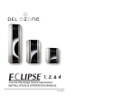
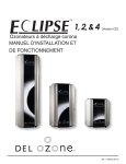
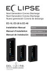
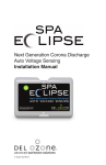
Next Generation Corona Discharge
Auto Voltage Sensing
EC-10, EC-20 & EC-40
Installation Manual
4-2162-01 Rev.A
IMPORTANT SAFETY INSTRUCTIONS
Read & Follow All Instructions
• Read this manual completely before attempting installation. Failure to install in
accordance with the installation instructions could void warranty and result in injury or
death.
• The DEL Eclipse electrical connection is to be attached to the pool controls, be sure the
pool controls are protected by a Ground Fault Circuit Interrupter (G.F.C.I.). If the DEL
Eclipse is connected to an independent electrical supply, then a G.F.C.I. must be installed
between the DEL Eclipse and the electrical supply.
• Warning - To reduce the risk of electrical shock, this device must be mounted such that it
is inaccessible to a person in the pool.
• A pressure wire connector is provided on the outside of the unit, marked with to permit
connection to a minimum No. 6 AWG (13.3 mm2) solid bonding conductor between this
point and any metal equipment, metal enclosures of electrical equipment, metal water
pipes, or conduit at least five (5) feet (1.5m) of the unit or as needed to comply with local
requirements.
• Install at least 5 feet (1.5 meters) from wall of pool using nonmetallic tubing. Install ozone
generator no less than one (1) foot above maximum water level to prevent water from
contacting electrical equipment. Install in accordance with the installation instructions.
• Follow all applicable electrical codes.
• Electric shock hazard. Be sure to turn power OFF and disconnect from power source
before any routine maintenance is performed. Failure to do so could result in serious
injury or death.
• The DEL Eclipse must be installed in an outdoor location, or indoors in a forced air
ventilated room, and installed so that the orientation is exactly as shown in Figure 1.
Install to provide water drainage of generator to protect electrical components.
• Mount the DEL Eclipse so that it is inaccessible to anyone in the pool. Never attempt any
servicing while unit is wet.
• Plastic ozone supply tubing is supplied with the Eclipse. Never replace this tubing with
metal tubing.
• Warning - Short-term inhalation of high concentrations of ozone and long term inhalation
of low concentrations of ozone can cause serious harmful physiological effects. DO NOT
inhale ozone gas produced by this device.
• For your safety, do not store or use gasoline, chemicals or other flammable liquids or
vapors near this or any other appliance.
• WARNING - To reduce the risk of injury, do not permit children to use this product unless
they are closely supervised at all times.
• A green-colored terminal or a terminal marked G, GR, Ground, Grounding, or the
symbol is located inside the supply terminal box or compartment. To reduce the risk
of electric shock, this terminal must be connected to the grounding means provided in
the electric supply service panel with a continuous copper wire equivalent in size to the
circuit conductors supplying this equipment.
• At least two lugs marked “BONDING LUGS” are provided on the external surface or
on the inside of the supply terminal box or compartment. To reduce the risk of electric
shock, connect the local common bonding grid in the area of the hot tub or spa to these
terminals with an insulated or bare copper conductor not smaller than No. 6 AWG.
SAVE THESE INSTRUCTIONS!
Eclipse Installation & Operations Manual
Table of Contents
Installation Instructions
SECTION 1. Overview............................................................................. 1
SECTION 2. Installation.......................................................................... 2
SECTION 3. Operation............................................................................ 6
SECTION 4. Maintenance....................................................................... 7
SECTION 5. Replacement Parts.......................................................... 10
Warranty................................................................................................ 12
Appendix .............................................................................................. 13
SECTION 1. Overview
1A.Description
The DEL Eclipse Series ozone generators described in this
manual are designed to provide the benefits of ozonated water in
an environmentally safe and effective manner. The high quality,
specially engineered components ensure efficient ozone output and
reliable performance.
As a result of proper use of the DEL Eclipse ozone generators,
unpleasant effects of traditional chemical use are virtually
eliminated. The DEL Eclipse ozone generators are safe and
harmless to your equipment when installed properly.
1B.Specifications
Power Requirements:
EC-10...........................110-250V, 0.10A max, 50-60 Hz
EC-20...........................110-250V, 0.20A max, 50-60 Hz
EC-40...........................110-250V, 0.31A max, 50-60 Hz
Location Requirements:
Mounting: Wall mount in a clean, protected area.
Ambient Temp.: 30°F - 120°F (0°C - 50°C)
1
Eclipse Installation & Operations Manual
1C.Warranty Summary
Limited Warranty:
1 year warranty on entire generator. See Warranty section for
limitations and details on obtaining warranty service.
SECTION 2. Installation
2A.Location
The DEL Eclipse units are designed for wall mounting. Mount
generator in a clean, protected area, either indoors or outdoors
(preferably out of direct sunlight). Locate generator out of reach
of sprinklers or drainage spouts. Allow sufficient access for
maintenance, all tubing, and electrical wires. Ozone generator
should be installed at least (not less than) one foot above the
maximum water level.
2B.Wall Mounting
1.Open the Enclosure Door and locate the three mounting holes on
the back wall of the Enclosure. There will be two holes located
5.77
2.68
3X
.25
5.77
3X
.25
2.68
19.60
12.40
EC-10 AND EC-20
EC-40
Figure 1: Mouting Hole Dimensions
2
Eclipse Installation & Operations Manual
near the top on the left and right and one located in the center
near the bottom. Refer to Figure 1 for clarification.
2.Install screws (or other hardware appropriate for the mounting
surface) through the two mounting holes near the top of the
enclosure. Install the last screw through the mounting hole
near the bottom of the enclosure. Mounting hardware must be
driven until the head fully contacts the enclosure wall. Mounting
hardware head must not be smaller than 0.25 inches (6.3 mm) in
diameter and the threads of the hardware must be smaller than
0.25 inches (6.3 mm) in diameter.
2C.Electrical
2C-1. Main Power
This device is intended to be installed by a certified electrical
technician, in accordance with local electrical codes. Connect
the DEL Eclipse to the pool timing clock so that the DEL Eclipse
operates simultaneously with the pool pump. The DEL Eclipse has
three available Knockouts for a 1/2” conduit fitting, two on each
side and one on the back. Remove only the ideal Knockout and
install the proper conduit fitting. Open the Enclosure and locate the
Terminal Block. Connect Line 1, Line 2, and Ground to the Terminal
Block as indicated by the label on the inside of the enclosure
door. Refer to the IMPORTANT SAFETY INSTRUCTIONS at the
beginning of this manual for important wiring information.
2C-2. Earth Grounding Lug
Using an 6 AWG (13.3 mm2) conductor, connect the Grounding lug
on the bottom of the DEL Eclipse, marked to an appropriate earth
contact.
2D.Plumbing
Ozone gas is introduced to the pool circulation line using a venturi
injector. Suction developed by the venturi allows the DEL Eclipse
generator to operate safely under vacuum.
Note: Water must not travel back to the ozone generator.
Mounting the unit above the water line and scheduled check valve
replacement will keep water from entering the DEL Eclipse.
2D-1. Plumbing the Injector Manifold
The Injector Manifold must be installed in the pool’s main return line
3
Eclipse Installation & Operations Manual
after all other pool equipment (pump, filter, heater, and cleaner).
Figure 2 shows the most basic installation. For installation with
additional sanitizers and pool cleaners, refer to Appendix A.
Eclipse
System
Heater
Filter
Pool
Pump
Injector
Manifold
Water Flow
Figure 2: Injector Manifold Mounting Location
Locate an appropriate section of the return line and install the
injector manifold with PVC cement. Be very careful to observe and
follow the correct water flow direction (as indicated by the arrow on
the injector manifold).
2D-2. Water Check Valve
If the pool equipment is mounted above the water line, a check
valve must be installed between the pump outlet and the Injector
Manifold. This will prevent the pump from draining and losing its
prime (when not in use).
Note: If a 1/3# DELCheckTM is used, do not install immediately after
chlorine feeders.
2D-3. Pressure Test
If a pressure test is required, it should be performed prior to
connecting the Ozone Gas Line. Install the 3/4” pipe cap provided
onto the Injector for the pressure test.
4
Eclipse Installation & Operations Manual
Eclipse
System
Ozone Tube
Ozone
Outlet Barb
Flow Meter Assembly
(Remove after testing)
Check Valve
Tube Adapter
Injector Assembly
Figure 3: Flow Test Assembly
2D-4. Flow Test - Refer to Figure 3.
1.Install Tube Adapter on injector. Use Teflon thread tape as
needed.
2.Connect the end of the Ozone Tube with the check valve
installed onto the Tube Adapter with the tube clamp provided.
3.Connect the longer end of the Flow Meter Assembly to the
Ozone Outlet Barb.
4.Connect the remaining ends of the Ozone Tube and the Flow
Meter Assembly together.
5.Hold the Flow Meter Assembly so that the clear plastic chamber
is vertical with the longer tubing toward the bottom.
6.Turn on the pool’s circulation system as this allows the Injector
Assembly to pull a vacuum. Under normal operation, the metal
ball in the Flow Meter Assembly will be floating in between its
Max and Min line. Under worst-case system conditions the
flowmeter ball should indicate at least a small amount of air flow.
Flow may be adjusted as described below.
Adjustable Injector Manifold: Gas flow can be controlled by
adjusting the Valve on the Manifold. Close the valve to increase gas
flow, open the Valve to decrease gas flow.
Rigid Injector Manifold: This Manifold is equipped with a
DELCheckTM spring loaded valve. It cannot be adjusted, but
5
Eclipse Installation & Operations Manual
provides a wide operating range. If more gas flow is necessary,
verify that other valves in the system are not inhibiting flow through
the Manifold. If you experience complications see TROUBLE
SHOOTING Section 4D.
7.After the system has been set for the correct flow rate. Remove
the Flow Meter Assembly and connect the remaining end of the
Ozone Tube to the Ozone Outlet Barb on the DEL Eclipse unit
with the tube clamp provided. Cut off the excess tubing so that
the line from the injector to the DEL Eclipse is as straight and
free from dips and loops as possible.
SECTION 3 Operation
3A.General
To achieve optimal performance from the ozone system, the pool
must be as clean as possible to start with.
1.Backwash or clean filters one day before starting the ozone
generator.
2.Superchlorinate pool water using a chlorine based shock
treatment prior to ozone system start-up.
3.Test pool chemistry and adjust pH between 7.4 and 7.6. Adjust
total alkalinity between 80 and 120 ppm.
4.Run pool filtration continuously for 24 hours prior to starting
ozone system.
3B.Initial System Start-Up
Upon completing all of the generator system connections and
cleaning the pool as outlined above, you are ready to start the
ozone generator.
1.Check electrical connections.
2.Check for proper voltage.
3.Turn on pool circulation system.
3C.Normal Operation
1.Indicator Lights: When the pool’s circulation system starts, the
Eclipse will power up and the green indicator lights on the ozone
cells will illuminate. Open the Enclosure Door to verify that all
indicator lights are green. The EC-10, EC-20, and EC-40 should
show 2, 4, and 6 indicators, respectively.
6
Eclipse Installation & Operations Manual
3D.System Shut-Down
The following sequence of steps must be followed for servicing or
for storage.
1.Disconnect the power to the ozone generator.
2.After the generator has been shut down, the pool water
circulation pump may be turned off.
3.If the system is to be shut down for an extended period,
disconnect the Ozone Tube from the unit.
3E.Water Chemistry
Regular chlorine or bromine testing should be performed as
normal. Ozone will be eliminating the majority of contaminants.
Therefore, only a small amount of chemicals will need to be added
- just enough to maintain a minimum of residual level of 0.5 - 1.0
ppm chlorine or 1.0 - 2.0 ppm bromine. Ozone is pH neutral thus
minimizing pH adjustments.
SECTION 4. Maintenance
4A.System Electromechanical Overview
Manifold
Power Supply
Mouting Screws
Power Supply Connecter
Power Supply
Bracket
Ozone Module
Fuse Holder
Grounding
Lugs
Terminal Block
Ozone Outlet
Barb
Figure 4: Eclipse Overview
7
Eclipse Installation & Operations Manual
4A-1. Ozone Module
The Eclipse Ozone Generators are constructed with high voltage
plasma gap Ozone Modules. The EC-10, EC-20, and EC-40 have 2,
4, and 6 modules, respectively. Each module has an indicator light
that signals it’s working properly. If the light goes out, replace the
module.
4B.System Maintenance
4B-1. The green indicator lights on the Ozone Modules
located inside the enclosure indicates that the Power Supply is
operating properly. When an indicator light goes out, replace the
corresponding Ozone Module. Regularly check inside the unit to
verify all the Ozone Modules are working.
4B-2. Each Ozone Module should be replaced after 15,000 hours
of operation. Even if the green indicator light(s) are glowing, the
Ozone Module may be producing less ozone after this period of
time due to contamination within the plasma gap ozone chamber.
4B-3. Regularly reinstall and check the flowmeter for proper flow.
Always remove the flow meter after confirming proper flow. Inspect
Ozone Tube for cracks or wear and replace as necessary.
4B-4. Replace the Ozone Tube every year or sooner, if needed.
If there is evidence of water leaking past the Check Valve toward
the Eclipse, shut down the unit immediately and replace the Ozone
Tube and Check Valve. If water entered the Eclipse, allow the unit
to dry completely before restarting. Evidence of water in the Eclipse
may void the warranty.
WARNING: Do NOT touch the ends of the Ozone Tube when
replacing. Trace amounts of nitric acid may be present and could
prove harmful if touched or ingested.
4B-5. While operating, check to see if bubbles are entering the
pool. If an MDV is installed, check the MDV for bubbles.
4C.Generator Servicing - Refer to Figure 4
4C-1. Opening the Unit
The Eclipse ozone generator may be serviced on the wall without
disconnecting any of the plumbing or wiring. Simply remove the two
screws on the right side of the Enclosure Door to open the unit.
8
Eclipse Installation & Operations Manual
4C-2. Ozone Module Replacement
The EC-10, EC-20, and EC-40 have 2, 4, and 6 Ozone Modules,
respectively. When the green indicator lights go out, the
corresponding Ozone Module will need to be replaced.
To replace an Ozone Module:
1.Disconnect the Ozone Module from the Manifold and pull the
Ozone Module from the Bracket so it hangs by its wires.
2.Locate the Power Supply Connector and disconnect it from the
wire harness.
3.Remove the Power Supply Mounting Screw; make sure to
note plastic spacer and the star washer positions for proper
reassembly. The Ozone Module and Power Supply can now be
removed from the unit.
4.Install the new Ozone Module by reversing the above steps.
4D.Trouble Shooting
Knowledge of electrical applications is required for trouble shooting.
Contact a certified electrician if you are unsure of your ability to
service the equipment. Improper servicing will void generator
warranty. If any condition persists contact DEL technical support
(see section 4E)
4D-1 Symptom: Module Indicator Lights not lit when pool system is
on.
1.No power to the ozone generator from the power source:
a.Check circuit breaker at the power distribution box.
b.Check for loose connections or wiring breaks from the power
distribution box to the generator.
c.The fuse in the unit has blown and needs to be replaced. The
fuse is a replaceable glass, .25” x 1.25”, 1 amp, slo-blo type.
2.G.F.C.I. has tripped.
a.Check power cord and reset G.F.C.I.
4D-2 Symptom: Flowmeter not indicating flow.
1.Injector not supplying adequate suction.
a.Check pump, filters, and skimmers to ensure water is flowing
through injector.
b.Ensure that there is no debris clogged inside the injector.
2.Tubing is impaired.
a.Check for kinks or clogs.
b.Check for cracks or cuts.
c.Check connections.
d.Check that the check valve is installed with the arrow pointing
towards the injector.
9
Eclipse Installation & Operations Manual
e.Be sure that the check valve has not become fouled with
debris. Disconnect the Ozone Tube from the injector. With the
pump running, cover the end of the injector with your thumb,
and feel for suction. If there is sufficient suction without the
check valve, replace the check valve with a new one.
4D-3 Symptom: Ozone Tube becomes yellow/brown and brittle.
1.The high concentration of ozone created by the Eclipse family of
ozone generators, as well as environmental conditions like UV
sunlight will tend to deteriorate the supplied Ozone Tube. This
is normal and acceptable, as long as the tubing doesn’t become
cracked and leak. Because of this, the Ozone Tube and Check
Valve should be replaced every year.
4D-4 Symptom: Can’t get ball to stay in the center of flowmeter.
1.The flowmeter provided is a general tool to setup flow to the
ozone generator. Flow will vary depending on pressures across
the injector, and therefore can be affected by things such as filter
or strainer loading. The ozone generator’s efficiency is optimized
near the center of the flow meter. The Eclipse ozone generator
will still perform well at flows above and below the recommended
range. However, the ball must be moving and not stuck on the
bottom of the flowmeter.
4E. Contact Information
For technical assistance:
Call: (805) 541-1601 ext. 293 or (800) 676-1335 ext. 293
Email: [email protected]
Or visit our website: www.delozone.com
SECTION 5. Replacement Parts
5A.Ordering Information
To locate a dealer nearest you call 1.800.676.1335 ext. 232 or visit
www.delozone.com.
Be prepared with the following information:
• Name
• Date Purchased
• Address
• Dealer Name
• DEL Model #
10
Eclipse Installation & Operations Manual
5B.Standard replacement parts list:
1.Ozone Module Kit.................................................9-1056-01
Each ozone module should be replaced after 15,000 hours of
use.
2.Ozone Tube Assembly..........................................9-0770-02
The Ozone Tube Assembly (includes Ozone Tube and Check
Valve) must be replaced once a year.
Note: The warranty is void if the parts listed above are not replaced
at recommended intervals.
11
Eclipse Installation & Operations Manual
DEL OZONE Eclipse™
LIMITED 1 YR WARRANTY
The limited warranty set forth below applies to products manufactured by DEL OZONE – 3580 Sueldo Street, San Luis
Obispo, California 93401, and sold by DEL OZONE or its authorized dealers. This limited warranty is given only to the first
retail purchaser of such products and is not transferable to any subsequent owners or purchasers of such products.
DEL Ozone warrants that it or its authorized dealers will repair or replace, at its option, any part of such products proven
to be defective in materials or workmanship within ONE (1) year from the date of retail purchase of such products. (All
parts) ANY REPAIR OR REPLACEMENT WILL BE WARRANTED ONLY FOR THE BALANCE OF THE ORIGINAL
WARRANTY PERIOD.
NOTE: USE ONLY DEL AUTHORIZED DEL REPLACEMENT PARTS. USE OF ANY OTHER PART(S) WILL VOID
THIS WARRANTY.
Any replaced parts must be returned to DEL OZONE for warranty evaluation.
THIS LIMITED WARRANTY DOES NOT INCLUDE ANY OF THE FOLLOWING:
(a)
(b)
(c)
(d)
(e)
Any repair or replacement of such parts necessitated by faulty installation, improper maintenance, improper
operation, misuse, abuse, negligence, accident, fire, flood, repair materials, and/or unauthorized accessories.
Any such products installed without regard to required local codes and accepted trade practices.
Damage to unit caused by water backflow;
Any implied warranty of merchantability or implied warranty of fitness for particular purpose, and such
warranties are hereby disclaimed.
DEL Ozone shall not be liable under any circumstances for loss of use of such product, loss of profits. direct
damages, indirect damages, consequential damages, and / or incidental damages.
This warranty gives you specific legal rights. You may have other rights which vary from state to state.
TO OBTAIN WARRANTY SERVICE:
DEL OZONE
3580 Sueldo, San Luis Obispo, CA 93401
Customer Service Number:
(800) 676-1335
Fax Number:
(805) 541-8459
E mail
[email protected]
PROVIDE:
1. Customer name, mailing address, and telephone.
2. Installer/Mechanical Contractor or Dealer name.
3. Unit Part Number, Serial Number or Manufacture Date, and date of purchase.
4. The date of failure.
5. A description of the failure.
After this information is provided, DEL Ozone may release a RETURN GOODS AUTHORIZATION (RGA) NUMBER. After receiving the RGA number
the part in question must be returned to DEL Ozone, freight prepaid, with the RGA number clearly marked on the outside of the package. All
preauthorized defective parts must be returned to DEL Ozone within thirty (30) days. Under no circumstances may any product be returned to DEL
Ozone without prior authorization. Returns without the assigned RGA number on the outside of the package will be refused and shipped back to the
sender at their expense. Upon receipt of preauthorized returned goods, DEL Ozone will repair or replace, at DEL Ozone’s option, the defective product(s)
and return them (freight prepaid for products under warranty). Buyer’s acceptance of the product and use thereof constitutes acceptance of these terms.
4-1398-01_Rev.D
12
Eclipse Installation & Operations Manual
Eclipse Installation – Plumbing
The DEL Ozone Eclipse works under vacuum. The Injector Manifold draws the ozone/air gas mixture out of the ozone
generator and mixes it into the water leaving behind some un-dissolved gas bubbles. These bubbles can affect certain
pool system components, so care must be taken when installing the ozone Injector Manifold.
The diagrams below cover common plumbing configurations. For other configurations or installation questions, please
call DEL Ozone Residential Pool & Spa Technical Support at 1 (800) 676-1335, ext. 293, or e-mail:
[email protected]
!
Pool Cleaners (i.e. Polaris 360): Always plumb the cleaner t-fitting before the Eclipse injector to prevent gas from
affecting the operation of the cleaner.
"
Salt Chlorinator: A Salt Chlorinator may be plumbed on either side of the Eclipse injector.
#
Chlorine Tab / Mineral Erosion Feeder: Always plumb the Eclipse injector after any erosion feeder to avoid gas
accumulating in the feeder.
$
In-Floor Cleaning System: The Eclipse Injector must be on a different pool return leg than any In-Floor Cleaning
system to avoid excess back pressure on the Injector. This will also prevent gas intrusion and high oxidizer levels in
zone valve and cleaner heads.
%
Water Features: Avoid plumbing the Injector Manifold into any leg with excessive back pressure such as those
going to fountains, restrictive wall fittings, etc.
&
DEL Total Eclipse: Also correct location for Total Eclipse By-Pass. Back pressure on Total Eclipse must be minimal.
Diagram 1: Pool Only
Pool
Cleaner
Heater
Sanitizer
!
"#
Sanitizer
"#
Eclipse
Injector
Manifold
Pool
Sanitizer
"
&
Eclipse
Diagram 2: Pool/Spa Combo
In-Floor
Cleaner
$
Actuator
Heater
Pool
Water
Features
%
To Spa
Sanitizer
"#
Eclipse
Injector
Manifold
Sanitizer
"
&
DEL Ozone, Inc.
www.delozone.com
Eclipse
13
4-1393-01_Rev.A
3580 Sueldo Street, San Luis Obispo, CA 93401
(800) 676-1335 [email protected]
www.delozone.com
EPA Estab. No. 071472-CA-001