1
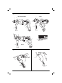
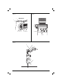
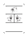
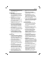
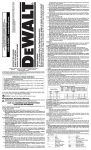
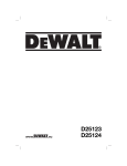
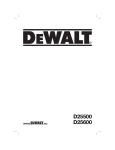
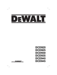
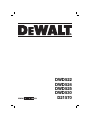
www.
.eu
DWD522
DWD524
DWD525
DWD530
D21570
Figure 1
DWD522/DWD524/DWD530
c
DWD525
c
d
d
g
g
b
b
e
a
a
e
j
j
i
c
d
g
h
b
a
e
D21570
j
Figure 3
Figure 2
l
b
k
a
m
e
j
1
Figure 4
Figure 5
n
DWD530/D21570
f
d
Figure 6
g
e
2
Figure 7
c
Figure 8
Figure 9
3
E NG L I S H
DUAL SPEED PERCUSSION DRILL
DWD522, DWD524, DWD525, DWD530, D21570
Congratulations!
You have chosen a DEWALT tool. Years of experience, thorough product development and innovation make
DEWALT one of the most reliable partners for professional power tool users.
Technical Data
Voltage
UK & Ireland
Type
Power input
No load speed
Collar diameter
Maximum chuck capacity
Bits
metal drilling low speed
wood, flat boring
bits, masonry drilling
optimum
maximum
diamond core
Weight
LPA
KPA
LWA
KWA
(sound pressure)
(sound pressure uncertainty)
(sound power)
(sound power uncertainty)
mm
mm
DWD522
230
–
1
950
0–1250 /
0–3500
43
13
DWD524
230
230/115
1
1100
0–1250 /
0–3500
43
13
DWD525
230
230/115
1
1100
0–1250 /
0–3500
43
13
DWD530
230
230/115
1
1300
0–1250 /
0–3500
43
13
D21570
230
230/115
1
1300
0–1250 /
0–3500
43
16
mm
mm
13
40
13
40
13
40
16
40
16
40
mm
mm
mm
kg
5–10
20
–
2.8
5–10
22
–
2.8
5–10
22
–
2.8
5–10
22
–
2.8
5–10
22
127
3.0
dB(A)
dB(A)
dB(A)
dB(A)
95
3
106
3
95
3
106
3
94
3
105
3
93
3
104
3
93
3
104
3
VAC
VAC
W
min-1
Vibration total values (triax vector sum) determined according to EN 60745:
Vibration emission value ah
Drilling into metal
ah,D =
Uncertainty K =
m/s²
m/s²
5.5
4.3
5.5
4.3
4
1.5
7
4.8
–
–
Vibration emission value ah
Impact drilling into concrete
ah,ID =
Uncertainty K =
m/s²
m/s²
18
6.3
18
6.3
15
1.9
16
4.6
16
4.6
Vibration emission value ah
Drilling into concrete
ah,DD =
Uncertainty K =
m/s²
m/s²
–
–
–
–
–
–
–
–
13
6.8
27
EN GLI S H
The vibration emission level given in this information
sheet has been measured in accordance with a
standardised test given in EN 60745 and may be
used to compare one tool with another. It may be
used for a preliminary assessment of exposure.
WARNING: The declared vibration
emission level represents the main
applications of the tool. However if the
tool is used for different applications,
with different accessories or poorly
maintained, the vibration emission may
differ. This may significantly increase the
exposure level over the total working
period.
An estimation of the level of exposure to
vibration should also take into account
the times when the tool is switched off
or when it is running but not actually
doing the job. This may significantly
reduce the exposure level over the total
working period.
Identify additional safety measures to
protect the operator from the effects of
vibration such as: maintain the tool and
the accessories, keep the hands warm,
organisation of work patterns.
Fuses
Europe
U.K. & Ireland
230 V tools
230 V tools
10 Amperes, mains
13 Amperes, in plugs
Definitions: Safety Guidelines
The definitions below describe the level of severity
for each signal word. Please read the manual and
pay attention to these symbols.
DANGER: Indicates an imminently
hazardous situation which, if not avoided,
will result in death or serious injury.
WARNING: Indicates a potentially
hazardous situation which, if not
avoided, could result in death or
serious injury.
CAUTION: Indicates a potentially
hazardous situation which, if not
avoided, may result in minor or
moderate injury.
NOTICE: Indicates a practice not
related to personal injury which, if
not avoided, may result in property
damage.
Denotes risk of electric shock.
Denotes risk of fire.
28
EC-Declaration of Conformity
MACHINERY DIRECTIVE
DWD522, DWD524, DWD525, DWD530, D21570
DEWALT declares that these products described
under “technical data” are in compliance with:
2006/42/EC, EN 60745-1, EN 60745-2-1.
These products also comply with Directive
2004/108/EC. For more information, please contact
DEWALT at the following address or refer to the
back of the manual.
The undersigned is responsible for compilation of the
technical file and makes this declaration on behalf of
DEWALT.
Horst Grossmann
Vice President Engineering and Product
Development
DEWALT, Richard-Klinger-Straße 11,
D-65510, Idstein, Germany
26.06.2010
WARNING: To reduce the risk of injury,
read the instruction manual.
General Power Tool Safety Warnings
WARNING! Read all safety warnings
and all instructions. Failure to follow
the warnings and instructions may result
in electric shock, fire and/or serious
injury.
SAVE ALL WARNINGS AND INSTRUCTIONS
FOR FUTURE REFERENCE
The term “power tool” in the warnings refers to your
mains-operated (corded) power tool or batteryoperated (cordless) power tool.
1) WORK AREA SAFETY
a) Keep work area clean and well lit.
Cluttered or dark areas invite accidents.
b) Do not operate power tools in explosive
atmospheres, such as in the presence of
flammable liquids, gases or dust. Power
tools create sparks which may ignite the dust
or fumes.
E NG L I S H
c)
Keep children and bystanders away while
operating a power tool. Distractions can
cause you to lose control.
2) ELECTRICAL SAFETY
a) Power tool plugs must match the outlet.
Never modify the plug in any way. Do
not use any adapter plugs with earthed
(grounded) power tools. Unmodified plugs
and matching outlets will reduce risk of
electric shock.
b) Avoid body contact with earthed or
grounded surfaces such as pipes,
radiators, ranges and refrigerators. There
is an increased risk of electric shock if your
body is earthed or grounded.
c) Do not expose power tools to rain or wet
conditions. Water entering a power tool will
increase the risk of electric shock.
d) Do not abuse the cord. Never use the
cord for carrying, pulling or unplugging
the power tool. Keep cord away from
heat, oil, sharp edges or moving parts.
Damaged or entangled cords increase the
risk of electric shock.
e) When operating a power tool outdoors,
use an extension cord suitable for outdoor
use. Use of a cord suitable for outdoor use
reduces the risk of electric shock.
f) If operating a power tool in a damp
location is unavoidable, use a residual
current device (RCD) protected supply.
Use of an RCD reduces the risk of electric
shock.
3) PERSONAL SAFETY
a) Stay alert, watch what you are doing and
use common sense when operating a
power tool. Do not use a power tool while
you are tired or under the influence of
drugs, alcohol or medication. A moment of
inattention while operating power tools may
result in serious personal injury.
b) Use personal protective equipment.
Always wear eye protection. Protective
equipment such as dust mask, non-skid
safety shoes, hard hat, or hearing protection
used for appropriate conditions will reduce
personal injuries.
c) Prevent unintentional starting. Ensure
the switch is in the off position before
connecting to power source and/or
battery pack, picking up or carrying the
tool. Carrying power tools with your finger
on the switch or energising power tools that
have the switch on invites accidents.
d) Remove any adjusting key or wrench
before turning the power tool on. A
wrench or a key left attached to a rotating
e)
f)
g)
part of the power tool may result in personal
injury.
Do not overreach. Keep proper
footing and balance at all times. This
enables better control of the power tool in
unexpected situations.
Dress properly. Do not wear loose
clothing or jewellery. Keep your hair,
clothing and gloves away from moving
parts. Loose clothes, jewellery or long hair
can be caught in moving parts.
If devices are provided for the connection
of dust extraction and collection facilities,
ensure these are connected and properly
used. Use of dust collection can reduce
dust-related hazards.
4) POWER TOOL USE AND CARE
a) Do not force the power tool. Use the
correct power tool for your application.
The correct power tool will do the job
better and safer at the rate for which it
was designed.
b) Do not use the power tool if the switch
does not turn it on and off. Any power
tool that cannot be controlled with the switch
is dangerous and must be repaired.
c) Disconnect the plug from the power
source and/or the battery pack from
the power tool before making any
adjustments, changing accessories, or
storing power tools. Such preventive safety
measures reduce the risk of starting the
power tool accidentally.
d) Store idle power tools out of the reach
of children and do not allow persons
unfamiliar with the power tool or these
instructions to operate the power tool.
Power tools are dangerous in the hands of
untrained users.
e) Maintain power tools. Check for
misalignment or binding of moving parts,
breakage of parts and any other condition
that may affect the power tool’s operation.
If damaged, have the power tool repaired
before use. Many accidents are caused by
poorly maintained power tools.
f) Keep cutting tools sharp and clean.
Properly maintained cutting tools with sharp
cutting edges are less likely to bind and are
easier to control.
g) Use the power tool, accessories and
tool bits etc., in accordance with these
instructions taking into account the
working conditions and the work to
be performed. Use of the power tool for
operations different from those intended
could result in a hazardous situation.
29
EN GLI S H
5) SERVICE
a) Have your power tool serviced by a
qualified repair person using only identical
replacement parts. This will ensure that the
safety of the power tool is maintained.
• Do not operate this tool for long periods of
time. Vibration caused by hammer action may
be harmful to your hands and arms. Use gloves
to provide extra cushion and limit exposure by
taking frequent rest periods.
Additional Specific Safety Rules for
Percussion Drills
• Air vents often cover moving parts and
should be avoided. Loose clothes, jewellery or
long hair can be caught in moving parts.
• Wear ear protectors when impact drilling.
Exposure to noise can cause hearing loss.
Residual Risks
• Use auxiliary handle(s), if supplied with the
tool. Loss of control can cause personal injury.
The following risks are inherent to the use of drills:
• Hold power tool by insulated gripping
surfaces, when performing an operation
where the cutting accessory may contact
hidden wiring or its own cord. Cutting
accessory contacting a “live” wire will make
exposed metal parts of the power tool “live” and
could give the operator an electric shock.
• Use clamps or another practical way to
secure and support the workpiece to a
stable platform. Holding the work by hand or
against your body leaves it unstable and may
lead to loss of control.
• Wear ear protectors when hammering
for extended periods of time. Prolonged
exposure to high intensity noise can cause
hearing loss. Temporary hearing loss or serious
ear drum damage may result from high sound
levels generated by hammerdrilling.
– Injuries caused by touching the rotating parts or
hot parts of the tool.
In spite of the application of the relevant safety
regulations and the implementation of safety
devices, certain residual risks cannot be avoided.
These are:
– Impairment of hearing.
– Risk of squeezing fingers when changing
accessories.
– Health hazards caused by breathing dust
developed when working in wood.
– Risk of personal injury due to flying particles.
– Risk of personal injury due to prolonged use.
Markings on Tool
The following pictograms are shown on the tool:
Read instruction manual before use.
• Wear safety goggles or other eye protection.
Hammering and drilling operations cause chips
to fly. Flying particles can cause permanent eye
damage. Wear a dust mask or respirator for
applications that generate dust. Ear protection
may be required for most applications.
• Always use the side handle supplied with the
tool. Tighten the side handle securely before
use. Keep a firm grip on the tool at all times.
Do not attempt to operate this tool without
holding it with both hands. Operating this
tool with one hand will result in loss of control.
Breaking through or encountering hard materials
such as re-bar may be hazardous as well.
• Always check core bits before usage. Never use
damaged core bits.
• Hammer bits and tools get hot during
operation. Wear gloves when touching them.
• Wear non-slip footwear to prevent injuries when
standing or walking on slippery surfaces.
• Only use cutting tools designed for this tool.
Use of non-recommended cutting tools may
lead to injuries due to loss of control.
30
Wear ear protection.
Wear eye protection.
DATE CODE POSITION (FIG. 1)
The Date Code (h), which also includes the year of
manufacture, is printed into the housing.
Example:
2010 XX XX
Year of Manufacture
Package Contents
The package contains:
1 Percussion drill
1 Side handle
1 Depth rod
1 Chuck key (D21570K only)
E NG L I S H
1 Instruction manual
1 Exploded drawing
• Check for damage to the tool, parts or
accessories which may have occurred during
transport.
• Take the time to thoroughly read and
understand this manual prior to operation.
Description (fig. 1, 4)
WARNING: Never modify the power
tool or any part of it. Damage or
personal injury could result.
a. Trigger switch
b. Reversing lever
c. Chuck
d. Speed/mode selector collar
e. Side handle
f. Indicator light (DWD530, D21570)
g. Main handle
h. Date code
i. Chuck key (D21570)
j. Lock-on button
To stop the tool in continuous operation, press the
switch briefly and release it. Always turn the tool off
when work is finished and before unplugging.
NOTE: Use lower speeds for starting holes, drilling
in plastics or ceramics or for driving screws.
REVERSING LEVER (FIG. 3)
The reversing lever (b), located above the trigger
switch, changes the direction of rotation of the
percussion drill and is used when backing out
screws and jammed drill bits.
To operate the tool in reverse, release the trigger
switch (a) and push the lever to the left (when
viewed from the chuck end).
To operate the drill in forward, release the trigger
switch and push the lever to the right (when viewed
from the chuck end).
Return the reversing lever to the forward position
after all operations in reverse are completed.
HIGH/LOW SPEED OPERATION (FIG. 1, 5)
The two speed gear drive in the dual range
percussion drill permits effective operation over an
extended range of applications with greater selection
of accessories.
INTENDED USE
For LOW SPEED operation, turn the collar (d) to the
drill bit symbol for drilling position 1.
Your heavy-duty percussion drill has been designed
for professional drilling and hammerdrilling
applications.
For HIGH SPEED operation, turn the collar (d) to the
drill bit symbol for drilling position 2.
The D21570 has been designed for professional dry
diamond drilling into masonry.
DO NOT use under wet conditions or in presence of
flammable liquids or gases.
These heavy-duty percussion drills are professional
power tools.
DO NOT let children come into contact with the
tool. Supervision is required when inexperienced
operators use this tool.
TRIGGER SWITCH (FIG. 3)
To start percussion drill, depress the trigger switch
(a). To stop percussion drill, release the trigger
switch.
VARIABLE SPEED (FIG. 3)
Variable speed permits speed control. The further
the trigger switch (a) is depressed, the higher the
speed of the percussion drill.
If necessary, press the lock-on button (j) for
continuous operation and release the switch. The
lock-on button works only in full speed, forward
rotation.
The gear train has been designed for shifting only
when the unit is off. It may be necessary, however,
to rotate the chuck slightly by hand to align the
gears while turning the collar.
NOTICE: DO NOT ATTEMPT TO
CHANGE SPEEDS by turning the collar
when the tool is running. Doing so will
damage the gear train.
HAMMER/DRILL SELECTOR (FIG. 1, 5)
To switch the tool from the drilling mode to the
hammering mode (or vice-versa) rotate the collar (d)
to the applicable symbol as shown in figure 5.
Turn the collar (d) to the drill bit symbol for drilling or
to the hammer symbol for hammerdrilling, as shown
in the figure.
TORQUE LIMITING CLUTCH
This tool is equipped with a torque limiting clutch
that reduces the maximum torque reaction
transmitted to the operator in case of jamming of a
drill bit. This feature also prevents the gearing and
electric motor from stalling. The torque limiting clutch
has been factory-set and cannot be adjusted.
31
EN GLI S H
E-CLUTCH ANTI-LOCK CONTROL™ (FIG. 4)
DWD530, D21570
Your DEWALT drill may come with an electronic
feature called E-CLUTCH Anti-Lock Control™. It is
designed to help you control the drill during a stall
and keep it from pulling out of your hands. This may
be encountered when drilling in steel or using large
bits in wood.
As a stall situation presents itself, the motor cycles
on and off for a set period of time. This reduces
the reaction of the stall and allows you to keep the
drill under control. Releasing the trigger resets the
E-Clutch and the unit will operate in normal mode
when the trigger is depressed again.
The E-CLUTCH Anti-Lock Control™ also
incorporates an overload protection feature designed
to help prevent the unit from becoming too hot
during high load applications.
If the unit becomes excessively hot during operation
this feature will cut the motor, The feature will
continue to cut the motor if it is restarted and placed
under a high load before it has cooled off.
Figure 4 shows the instruction label (n) mounted on
the housing. There are two alert modes.
1. Engaged Mode: When a stall situation
presents itself, the light will come on and stay
on as the motor cycles on and off for a set
period of time before the E-CLUTCH Anti-Lock
Control™ completely shuts the tool down.
When the unit is running in normal mode, there
will be no light.
2. Problem Mode: A series of continual flashes
as the trigger is pulled indicates that the
electronics are no longer functioning. The tool
may still be able to function without the benefit
of E-CLUTCH Anti-Lock Control™ but should
be serviced as soon as possible.
Electrical Safety
The electric motor has been designed for one
voltage only. Always check that the power supply
corresponds to the voltage on the rating plate.
Your DEWALT tool is double insulated in
accordance with EN 60745; therefore no
earth wire is required.
WARNING: 115 V units have to
be operated via a fail-safe isolating
transformer with an earth screen
between the primary and secondary
winding.
32
This product is intended to be used with
a safety transformer manufactured to
BSEN61558 and BS4343. Never work
without this transformer in place.
If the supply cord is damaged, it must be replaced
by a specially prepared cord available through the
DEWALT service organisation.
Mains Plug Replacement
(U.K. & Ireland Only)
If a new mains plug needs to be fitted:
• Safely dispose of the old plug.
• Connect the brown lead to the live terminal in
the plug.
• Connect the blue lead to the neutral terminal.
WARNING: No connection is to be
made to the earth terminal.
Follow the fitting instructions supplied with good
quality plugs. Recommended fuse: 13 A.
Using an Extension Cable
If an extension cable is required, use an approved
3–core extension cable suitable for the power
input of this tool (see technical data).The minimum
conductor size is 1.5 mm2; the maximum length
is 30 m.
When using a cable reel, always unwind the cable
completely.
ASSEMBLY AND ADJUSTMENTS
WARNING: To reduce the risk of
injury, turn unit off and disconnect
machine from power source before
installing and removing accessories,
before adjusting or changing setups or when making repairs. Be sure
the trigger switch is in the OFF position.
An accidental start-up can cause injury.
Side Handle (fig. 2)
WARNING: To reduce the risk of
personal injury, ALWAYS operate
the tool with the side handle
properly installed. Failure to do so
may result in the side handle slipping
during tool operation and subsequent
loss of control. Hold tool with both
hands to maximize control.
A side handle (e) is supplied with this percussion
drill. It clamps to the front of the gear case as
shown in figure 2 and can be rotated 360˚ for rightor left- hand use.
E NG L I S H
After the side handle is rotated into position, it
should be pushed rearward until the slots (k) on
the lip of the side handle are aligned with and
fully engaged with the projecting tabs (m) on the
underside of the gear case. The side handle is then
securely clamped by turning clockwise until tight.
OPERATION
Instructions for Use
WARNING: To reduce the risk
of serious personal injury, turn
tool off and disconnect tool from
power source before making any
adjustments or removing/installing
attachments or accessories.
WARNING:
• Always observe the safety instructions
and applicable regulations.
• To reduce the risk of personal
injury, ALWAYS ensure workpiece
is anchored or clamped firmly.
If drilling thin material, use a wood
“back-up” block to prevent damage to
the material.
• To reduce the risk of personal
injury, always operate the tool
with the side handle properly
installed. Failure to do so may result
in the side handle slipping during tool
operation and subsequent loss of
control. Hold tool with both hands to
maximize control.
• Do not attempt to tighten or loosen
drill bits (or any other accessory) by
gripping the front part of the chuck
and turning the tool on. Damage to
the chuck and personal injury may
occur.
• Burn Hazard. ALWAYS wear gloves
when changing bits. Accessible metal
parts on the tool and bits may get
extremely hot during operation. Small
bits of broken material may damage
bare hands.
Proper Hand Position (fig. 6)
WARNING: To reduce the risk of
serious personal injury, ALWAYS use
proper hand position as shown.
WARNING: To reduce the risk of
serious personal injury, ALWAYS hold
securely in anticipation of a sudden
reaction.
Proper hand position requires one hand on the side
handle (e) with the other hand on the main handle
(g).
Keyless Chuck (fig. 7–9)
DWD522, DWD524, DWD525, DWD530
The DWD522, DWD524, DWD525 and DWD530
feature a keyless chuck (c) for greater convenience.
To insert a drill bit or other accessory, follow the
steps listed below.
1. Grasp the rear half of the chuck with one hand
and use your other hand to rotate the front half
counterclockwise, as shown in figure 7. Rotate
far enough so that the chuck opens sufficiently
to accept the desired accessory.
2. Insert the bit or other accessory about 3/4"
(19 mm) into the chuck and tighten securely
by holding the rear half of the chuck and
rotating the front portion in the clockwise
direction. When the chuck is nearly tightened,
you will hear a clicking sound. After 4–6 clicks,
the chuck is securely tightened around the
accessory.
3. To release the accessory, repeat step 1 listed
above.
WARNING: Do not attempt to tighten
drill bits (or any other accessory) by
gripping the front part of the chuck
and turning the tool on. Damage to the
chuck and personal injury may result.
KEYLESS CHUCK REMOVAL (FIG. 8)
Tighten the chuck around the shorter end of a hex
key (not supplied) of 1/4" (6 mm) or greater size.
Using a soft hammer or piece of wood, strike the
longer end in the counterclockwise direction. This
will loosen the chuck so that it can be unscrewed
by hand.
KEYLESS CHUCK INSTALLATION (FIG. 9)
Screw the chuck on by hand as far as it will go.
Tighten the chuck around the shorter end of a 1/4"
(6 mm) or larger hex key (not supplied). Strike the
longer end in the clockwise direction with a soft
hammer.
Keyed Chuck (fig. 1)
D21570
The D21570 features a keyed chuck (c). To insert
a drill bit or other accessory, follow the steps listed
below.
1. Tighten chuck collar by hand.
33
EN GLI S H
2. Place chuck key in each of the three holes, and
tighten in clockwise direction. It’s important to
tighten chuck with all three holes to prevent
slippage.
To release bit, turn chuck key counterclockwise
in just one hole, then loosen the chuck by hand.
Any authorized DEWALT service center can install a
keyless chuck in place of a keyed chuck.
Depth Rod (fig. 2)
TO ADJUST THE DEPTH ROD (L):
Loosen the handle (e) and move rod so that the
distance between the end of the rod and the end of
the bit equals the desired drilling depth. When drilling
with depth rod, stop when end of rod reaches
surface of material.
Drilling
Turn the collar to the drill bit symbol for drilling or to
the hammer symbol for hammerdrilling. Install and
tighten the desired drill bit in the chuck.
DRILLING OPERATION
Select the desired speed/torque range using the
speed selector collar to match the speed and torque
to the planned operation.
1. For WOOD, use twist bits, spade bits, power
auger bits or hole saws. For METAL, use highspeed steel twist drill bits or hole saws. Use
a cutting lubricant when drilling metals. The
exceptions are cast iron and brass which should
be drilled dry. For MASONRY, use carbidetipped bits or masonry bits. A smooth, even
flow of dust indicates the proper drilling rate.
2. Always apply pressure in a straight line with the
bit. Use enough pressure to keep the drill bit
biting, but do not push hard enough to stall the
motor or deflect the bit.
3. Hold tool firmly with both hands to control the
twisting action of the drill.
WARNING: Drill may stall if overloaded
causing a sudden twist. Always expect
the stall. Grip the drill firmly with both
hands to control the twisting action and
avoid injury.
4. IF DRILL STALLS, it is usually because it
is being overloaded. RELEASE TRIGGER
IMMEDIATELY, remove drill bit from work,
and determine cause of stalling. DO NOT
CLICK TRIGGER OFF AND ON IN AN
ATTEMPT TO START A STALLED DRILL –
THIS CAN DAMAGE THE DRILL.
34
5. To minimize stalling or breaking through the
material, reduce pressure on drill and ease the
bit through the last fractional part of the hole.
6. Keep the motor running when pulling the bit
back out of a drilled hole. This will help prevent
jamming.
7. With variable speed drills there is no need to
center punch the point to be drilled. Use a
slow speed to start the hole and accelerate by
squeezing the trigger harder when the hole is
deep enough to drill without the bit skipping out.
HAMMERDRILL OPERATION
1. When drilling, use just enough force on the
hammer to keep it from bouncing excessively
or “rising” off the bit. Too much force will cause
slower drilling speeds, overheating and a lower
drilling rate.
2. Drill straight, keeping the bit at a right angle to
the work. Do not exert side pressure on the bit
when drilling as this will cause clogging of the
bit flutes and a slower drilling speed.
3. When drilling deep holes, if the hammer speed
starts to drop off, pull the bit partially out of
the hole with the tool still running to help clear
debris from the hole.
4. For masonry, use carbide-tipped bits or
masonry bits. A smooth even flow of dust
indicates the proper drilling rate.
DIAMOND DRILLING
D21570
The D21570 is designed for dry diamond drilling into
masonry up to 127 mm.
For diamond drilling above this diameter in masonry
and regular large diameter diamond drilling in
masonry and concrete, we advise the use of a
DEWALT D21580, D21582 or D21583 diamond core
drill.
Use speed 2 for diamond core bits with diameters
between 22–68 mm. Always use speed 1 for
diamond core bits between 68 mm and 127 mm in
diameter.
Follow the core bit or manufacturer’s
recommendations for using the accessory.
NOTE: Always use core bits with integral centredrill
systems.
1. Insert the centredrill into its holder in the centre
of the core bit.
Drill at low speed until the core penetrates the
surface approximately 5–10 mm.
E NG L I S H
2. Remove and unplug the machine.
3. Remove the centredrill from its holder.
4. Plug the machine in and insert the core bit into
the workpiece.
5. Begin drilling, increasing to full speed and drill to
the desired depth.
MAINTENANCE
Your DEWALT power tool has been designed to
operate over a long period of time with a minimum
of maintenance. Continuous satisfactory operation
depends upon proper tool care and regular cleaning.
WARNING: To reduce the risk of
injury, turn unit off and disconnect
machine from power source before
installing and removing accessories,
before adjusting or changing
set-ups or when making repairs.
Be sure the trigger switch is in the OFF
position. An accidental start-up can
cause injury.
Lubrication
Your tool was properly lubricated before leaving the
factory. In from two to six months, depending upon
use, take or send your tool to an authorised service
centre for a complete cleaning, inspection and
lubrication. Tools used constantly on production jobs
will need relubrication more often. Also, tools “out
of service” for long periods should be relubricated
before being put back to work.
Cleaning
WARNING: Blow dirt and dust out of
the main housing with dry air as often as
dirt is seen collecting in and around the
air vents. Wear approved eye protection
and approved dust mask when
performing this procedure.
Optional Accessories
WARNING: Since accessories, other
than those offered by DEWALT, have
not been tested with this product, use
of such accessories with this tool could
be hazardous. To reduce the risk of
injury, only DEWALT recommended
accessories should be used with this
product.
Consult your dealer for further information on the
appropriate accessories.
Protecting the Environment
Separate collection. This product must
not be disposed of with normal
household waste.
Should you find one day that your DEWALT product
needs replacement, or if it is of no further use to you,
do not dispose of it with household waste. Make this
product available for separate collection.
Separate collection of used products
and packaging allows materials to be
recycled and used again. Re-use of
recycled materials helps prevent
environmental pollution and reduces
the demand for raw materials.
Local regulations may provide for separate collection
of electrical products from the household, at
municipal waste sites or by the retailer when you
purchase a new product.
DEWALT provides a facility for the collection and
recycling of DEWALT products once they have
reached the end of their working life. To take
advantage of this service please return your product
to any authorised repair agent who will collect them
on our behalf.
You can check the location of your nearest
authorised repair agent by contacting your local
DEWALT office at the address indicated in this
manual. Alternatively, a list of authorised DEWALT
repair agents and full details of our after-sales
service and contacts are available on the Internet at:
www.2helpU.com.
WARNING: Never use solvents or
other harsh chemicals for cleaning the
non-metallic parts of the tool. These
chemicals may weaken the materials
used in these parts. Use a cloth
dampened only with water and mild
soap. Never let any liquid get inside the
tool; never immerse any part of the tool
into a liquid.
35
EN GLI S H
GUARANTEE
DEWALT is confident of the quality of its
products and offers an outstanding guarantee
for professional users of the product. This
guarantee statement is in addition to and in
no way prejudices your contractual rights as a
professional user or your statutory rights as a
private non-professional user. The guarantee
is valid within the territories of the Member
States of the European Union and the
European Free Trade Area.
• 30 DAY NO RISK SATISFACTION GUARANTEE •
If you are not completely satisfied with the
performance of your DEWALT tool, simply
return it within 30 days, complete with all
original components, as purchased, to
the point of purchase, for a full refund or
exchange. The product must have been
subject to fair wear and tear and proof of
purchase must be produced.
• ONE YEAR FREE SERVICE CONTRACT •
If you need maintenance or service for your
DEWALT tool, in the 12 months following
purchase, you are entitled to one service free
of charge. It will be undertaken free of charge
at an authorised DEWALT repair agent. Proof
of purchase must be produced. Includes
labour. Excludes accessories and spare parts
unless failed under warranty.
• ONE YEAR FULL WARRANTY •
If your DEWALT product becomes defective
due to faulty materials or workmanship
within 12 months from the date of purchase,
DEWALT guarantees to replace all defective
parts free of charge or – at our discretion –
replace the unit free of charge provided that:
• The product has not been misused;
• The product has been subject to fair
wear and tear;
• Repairs have not been attempted by
unauthorised persons;
• Proof of purchase is produced;
• The product is returned complete with all
original components.
If you wish to make a claim, contact your
seller or check the location of your nearest
authorised DEWALT repair agent in the
DEWALT catalogue or contact your DEWALT
office at the address indicated in this manual.
A list of authorised DEWALT repair agents and
full details of our after-sales service is available
on the Internet at: www.2helpU.com.
36
Belgique et
Luxembourg
België en
Luxemburg
Black & Decker - DEWALT
Nieuwlandlaan 7, IZ Aarschot B156
B-3200 Aarschot
Danmark
DEWALT
Sluseholmen 2-4
2450 København SV
Tlf:
70201511
Fax: 70224910
www.dewalt.dk
Deutschland
DEWALT
Richard Klinger Str. 11
65510 Idstein
Tel:
06126-21-1
Fax: 06126-21-2770
www.dewalt.de
Ελλάς
Black & Decker (Ελλάς) Α.Ε.
Στράβωνος 7 & Βουλιαγμένης 159
Γλυφάδα 16674, Αθήνα
España
DEWALT
Parque de Negocios “Mas Blau”
Edificio Muntadas, c/Bergadá, 1, Of. A6
08820 El Prat de Llobregat (Barcelona)
Tel:
934 797 400
Fax: 934 797 419
www.dewalt.es
France
DEWALT
5, allée des hêtres
BP 30084, 69579 Limonest Cedex
Tel:
04 72 20 39 20
Fax: 04 72 20 39 00
www.dewalt.fr
Schweiz
Suisse
Svizzera
DEWALT
In der Luberzen 40
8902 Urdorf
Tel:
01 - 730 67 47
Fax: 01 - 730 70 67
www.dewalt.ch
Ireland
DEWALT
Calpe House Rock Hill
Black Rock, Co. Dublin
Tel:
00353-2781800
Fax: 00353-2781811
www.dewalt.ie
Italia
DEWALT
Viale Elvezia 2
20052 Monza (Mi)
Tel:
800-014353
Fax: 039-2387592
www.dewalt.it
Nederlands
Black & Decker - DEWALT
Joulehof 12
4600 AB Bergen Op Zoom
Tel:
+31 164 283 063
Fax: +31 164 283 200
www.dewalt.nl
Norge
DEWALT
Postboks 4613, Nydalen
0405 Oslo
Tel:
45 25 13 00
Fax: 45 25 08 00
www.dewalt.no
Österreich
DEWALT
Werkzeug Vertriebsges m.b.H
Oberlaaerstrasse 248
A-1230 Wien
Tel:
01 - 66116 - 0
Fax: 01 - 66116 - 14
www.dewalt.at
Portugal
DEWALT
Centro de Escritórios de Sintra Avenida Almirante
Gago Coutinho, 132/134, Edifício 142710-418 Sintra
2710-418 Lisboa
Tel:
214 66 75 00
Fax: 214 66 75 75
www.dewalt.pt
Suomi
DEWALT
Tekniikantie 12
02150 Espoo, Finland
Puh: 010 400 430
Faksi: 0800 411 340
www.dewalt.fi
Sverige
DEWALT
Box 94
431 22 Mölndal
Tel:
031 68 61 00
Fax: 031 68 60 08
www.dewalt.se
Türkiye
KALE Hırdavat ve Makina A.Ş.
Defterdar Mah. Savaklar Cad. No:15
Edirnekapı / Eyüp / İSTANBUL 34050 TÜRKİYE
Tel: 0212 533 52 55
Faks: 0212 533 10 05
www.dewalt.com.tr
United
Kingdom
DEWALT
210 Bath Road; Slough, Berks SL1 3YD
Middle East
Africa
DEWALT
P.O. Box - 17164,
Jebel Ali (South Zone), Dubai, UAE
N093407
Dutch Tel: +32 70 220 063
French Tel: +32 70 220 062
Fax: +32 70 225 585
Fax: +32 70 222 441
www.dewalt.be
Τηλ:
+30 210 8981-616 www.dewalt.gr
Service: +30 210 8981-616
Φαξ:
+30 210 8983-570
Tel:
Fax:
01753-56 70 55
01753-57 21 12
www.dewalt.co.uk
Tel:
+971 4 8863030
Fax: +971 4 8863333
www.dewalt.ae
10/10