1
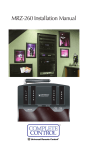
MRX-1 Installation Manual
Network Base Station
COMPLETE
CONTROL
™
Universal Remote Control®
MRX-1 Installation Manual ©2010 Universal Remote Control, Inc.
The information in this manual is copyright protected. No part of this manual may be copied or reproduced in any form without prior written consent
from Universal Remote Control, Inc.
UNIVERSAL REMOTE CONTROL, INC. SHALL NOT BE LIABLE FOR OPERATIONAL, TECHNICAL OR EDITORIAL ERRORS/OMISSIONS MADE IN
THIS MANUAL.
The information in this manual may be subject to change without prior
notice.
Complete Control is a registered trademark of Universal Remote Control,
Inc.
All other brand or product names are trademarks or registered trademarks
of their respective companies or organizations.
500 Mamaroneck Avenue, Harrison, NY 10528
Phone: (914) 835-4484 Fax: (914) 835-4532
TABLE OF CONTENTS
Introduction
1
Features and Benefits
2
Parts Guide
2
Front and Rear Panel Descriptions
3
Network Installation
4
Optimizing IR Flasher Levels
5
Integrating Optional RFTX-1 to control URC LIghting
6
Integrating Optional Video or Voltage Sensors
7
Integrating RS-232 and Relays
10
Network Discovery
13
Overview of IR Routing
16
Network or RF Setup in CCP
16
IR over Narrow Band via Optional RFX-250
18
Connecting multiple MRX-1’s via RF Out
20
Frequently Asked Questions
21
Specifications
21
USA Limited Warranty Statement
22
Warning
23
MRX-1 BASE STATION
Introduction
The MRX-1 Network Base Station receives IR and Serial commands
from any URC Network Controls (like the KP-4000, MX-6000 or MX5000) over the network. Each MRX-1 has a unique MAC Address,
which allows correct routing to multiple MRX-1 units throughout the
home.
In installations with URC RF Lighting, the optional RFTX-1 transmitter
will transmit RF commands from all URC Network Control’s. This
enables installations with multiple MRX-1’s and RFTX-1’s to become
whole house lighting control systems capable of multiple room paths
and scenes.
In addition, the MRX-1 offers traditional IR only control from URC
Narrow Band RF Controls via an optional RFX-250.
1. The KP-4000 communicates over the
LAN (Local Area Network) to IP controlled components and the URC MRX1 Network Base Station.
2. The MRX-1 receives commands and
controls the components via IR or
Serial.
WiFi Router
IR Controlled Device
3. Self-adhesive “Flashers” affix to
the Infrared sensors on the front
panels of your client’s components. The Flashers relay commands to components. The flashers plug in to the MRX-1 rear
flasher line outputs via their 10
foot cables. The MRX-1 can also
connect to components with rear
panel IR Inputs via its adjustable
IR Line Outputs.
Page 1
MRX-1 BASE STATION
Features and Benefits
The Bridge for Network Remotes and Keypads
The MRX-1 enables IR and RS-232 devices to be controlled by URC
Network Controls.
2-Way RS-232 Thermostats, Security Systems, Home Theater AVRS
and Multi-Zone Matrixes
Via the unique URC 2-Way database installers can drag and drop
2-Way pre-programmed modules into any URC Network Control
powered by the MRX-1’s two RS-232 ports. RS-232 components
can display Volume Pop Ups, Status displays, Tuner Modules, 2Way Transport Controls, etc.
Whole House URC Lighting via RFTX-1
Via the RFTX-1 transmitter, the MRX-1 can relay commands from
any URC Network Control to URC Lighting devices. By installing
multiple MRX-1/RFTX-1 relay stations around a home, installers can
create seamless coverage of any size house, allowing lighting paths
and whole house scenes.
Utilize MRX-1 Sensor Port to Automate TOAD Devices
The MRX-1 offers URC Network Controls automation capability for
devices that do not have discrete codes. It is equipped with a sensor port compatible with optional URC video or voltage sensors,
thus an installer can program macros that test whether a device is
on or off before issuing input commands etc.
Control Devices with Relays
URC Network Controls can control lifts, screens etc. via the MRX1’s NO, NC or Momentary set of contacts.
Traditional Narrow Band RF
Complete Control remotes and keypads can also control the same
IR devices with an optional RFX-250 or RFX-250i.
Parts Guide
The MRX-1 Network Base Station includes:
1 - MRX-1 Network Base Station
1 - 12V-1000mA Power Supply
6 - Visible Emitters with 10 foot plug
in cables including 1 pink sleeved
emitter for the RFTX-1 port
1 - Two Meter 3.5mm Stereo to
3.5mm Stereo (for daisy chaining
multiple MRX-1 with one RFX250)
1 - Adjustment Tool
1 - Mounting Plate for wall mounting
the MRX-1
Page 2
MRX-1 BASE STATION
Front and Rear Panel Descriptions
Front
The front panel consists of 4 indicator lights which will illuminate
when in use.
Power
Status
Reset: Bottom
Ethernet
Sensor
Power: Illuminates when the power supply is connected to an outlet
Status: Flashes in blue when an RF or Network signal is received.
Sensor: Illuminates to indicate that it is sensing the presence of
composite video or AC or DC voltage.
Ethernet: Illuminates when connected to a Network Router
Reset: Press the reset button located under the MRX-1 to restart the
unit.
Rear
The rear panel ports are:
Power
Relay:NO,
NC, COM
IR Outputs: #1-6
RFTX Port: #6
Sensor
Ethernet RS-232 Ports
IR IN
RF IN
RF ID
RF Out
Power: Provides connection to included 12V/1Amp Power Supply.
Ethernet: Provides connection to LAN(Local Area network) via RJ45
cable.
Relay NO, NC, COM: Provides configurable switch closure control.
RS-232 Ports: Two RS232 ports provides direct control.
Sensor: Provides connection to one URC Voltage Sensor (VS-1006)
or to one URC Video Sensor (VID-6) for status in sensor based
macros.
IR IN: Allows MRX-1 control from a base station such as a MRF-260
(IR Routing capability is lost from commands coming from the MRF260)
Page 3
MRX-1 BASE STATION
IR Outputs: Connect emitters for IR control of connected devices.
RFTX Port: Dual port #6 for the RFTX-1 connecting cable or included sleeved IR emitter.
RF IN: Connects to a optional single RFX-250 (refer to manual)
RF Out: Used for daisy chaining MRX-1s for RF Operation (Refer to
RFX-250 manual)
RF ID: 15 unique RF ID's provide RF control and routing to multiple
MRX-1’s in the same home. (RF ID #0, the interference "sniffing" position, is used to detect RF interference in the area.)
Network Installation
The MRX-1 is a network base station that allows full control of your
components. Once installed to the network, and a button is pressed
on the remote, a command is transferred over the customer’s network to the MRX-1 which sends IR, RS232 or Relay commands to
the devices you specify. Note that the MRX-1 can only be utilized
by URC Network Controls.
1. Connect the Ethernet cable (RJ45) to the rear of the MRX-1 and
into the network router.
2. Connect your laptop into the same network as the MRX-1.
3. Plug flashers into any of the six flasher ports on the rear of the
MRX-1. If you utilize IR output #6, you must use the pink
sleeved emitter. IR Output #6 is a dual purpose port, it can be
used for IR control or to connect the RFTX-1 for URC Lighting.
Page 4
MRX-1 BASE STATION
Optimizing IR Flasher Levels
Test a few commands for each device before fixing the flasher in
place on the front panel of a device.
Since TiVo, Replay TV, Satellite Receivers and Cable Boxes are all
extremely sensitive to IR overload or saturation, you should test
them thoroughly. Put up the on screen guide and test the navigation
arrows. Compare operation via RF to the original remote control.
Operation should be identical. If operation is inconsistent or sluggish, lower the IR line output and/or reposition the flasher.
If you still have sluggish operation, check that the remote control is
set to a particular LINE OUT, rather than ALL. When IR commands
are sent to all the flashers in a cabinet, you can have difficulty
adjusting the IR Output. Reprogram the remote control to send IR
commands only via a specific (1-6) Line Output, then readjust the
IR Line Output level.
Note: Line 6 is a dual port and requires the included sleeved emitter for long term IR use.
1. Connect an IR emitter to each IR output and run the emitter
wire to the front panel of each component. DO NOT STICK the
emitter in place. ADJUST the level first.
2. Adjust each of the IR Output levels with the included adjustment tool for best operation . If the component operates best at
minimum level, but is still operating sluggishly or intermittently,
move the emitter farther away from the components IR sensor.
IR Outputs:These ports can be conditioned as discrete, ‘routed’
outputs that only send IR commands to the specific device that
each emitter is attached to. This allows selective control of multiple
same-brand, same-model components, (multiple DVD players, SAT
receivers, etc.) and assures accurate control in that a given component’s commands are routed only to it’s dedicated IR output and
emitter, preventing IR splash from multiple emitters flashing at the
same time. Port #6 is a dual port with the RFTX-1 and requires a
sleeved emitter when in use as an IR emitter. POLARITY: Tip=IR
data, Sleeve=GND.
Page 5
MRX-1 BASE STATION
Integrating Optional RFTX-1 to control URC Lighting
RFTX-1
The RFTX-1 provides control of the URC Lighting
1. Simply plug the RFTX-1 with the 10’ pink connecting cable
(included with the RFTX-1) into the MRX-1 pink fixed port #6.
2. Set the RFTX-1 to either 418MHz or 433MHz.
Select either
418MHz or
433MHz
3. Set the URC Lighting Device in the CCP Editor to Network and
set the IR output to Port #6.
4. Download to the MX remote and begin controlling your lights.
Page 6
MRX-1 BASE STATION
Integrating Optional Video or Voltage Sensors
Voltage Power Sensor VS-1006
The VS-1006 Voltage Power Sensor allows voltage output of a system component to be used to monitor that component’s ON/OFF
status for power management when the device does not have discrete commands or a composite video output is not available for
video sensing. Some components provide 12V Status outputs while
with other applications, a DC power supply plugged into a component’s switched outlet can be used to provide device status.
Connections
Control Voltage Out/Switched AC Out (VS-1006)
When using a switched AC outlet, an AC or DC power supply
adapter can be used to trigger a VS-1006 Voltage Sensor. Using AC
or unregulated DC adapters is recommended given the instant
ON/OFF characteristics such supplies. Regulated DC adapters are
slower to respond when turned on and off and are therefore not
considered ideal for status sensing. RATING: 3-25V AC or DC.
1. Using a two conductor stranded 24-14 AWG wire, connect the
Control Voltage Out of the sensed device, or stripped ends of a
Power Adapter, to the Two-Pin Plug In Connector on the VS-1006.
Polarity is not critical with the VS-1006, as it can sense AC or DC.
2. If using a Power Adapter, plug it in to the Switched Outlet on the
Sensed Device.
3. Connect the 4-circuit mini plug from the VS-1006 to the appropriate Video or Voltage Sensor Input on the MRX-1 Rear Panel.
4. Once the system has been powered up, the VS-1006 Power LED
should illuminate Red.
5. To test Voltage Sensing, turn the Sensed Device on. The Sensor
LED on the MRX-1 front panel should illuminate in blue. Turn
the Sensed Device off and the LED should turn off as well. If not,
check the connections and measure the device control out or
power adapter with a volt meter to confirm voltage output.
Current Sensing AC Outlet (VS-1006)
1. Connect the Power cord from the sensed device to a sensed AC
outlet on a current sensing AC outlet.
2. Using two-conductor stranded 24-14AWG wire, connect the conPage 7
MRX-1 BASE STATION
trol voltage out of the current sensor to the two-pin plug-in connector on the VS-1006. The VS-1006 can sense AC or DC so
polarity is not critical.
3. Connect the 4-circuit mini plug from the VS-1006 to the sensor
input on the MRX-1 rear panel.
4. Plug the power cord on the current sensing device into an
unswitched AC outlet.
5. Once the system has been powered up, the VS-1006 Power LED
should illuminate Red.
6. To test Voltage Sensing, turn the Sensed Device on. The Sensor
LED on the MRX-1 front panel should illuminate in blue. Turn
the Sensed Device off and the LED should turn off as well. If not,
check the connections and measure the device control out with a
volt meter to confirm voltage output. Also confirm that the
Sensed Device’s Power Cord is connected to a Sensed Outlet.
VID-6 Video Sensor Cable
The Video Sensor Cable VID-6 is a special cable for sensing composite video. When composite video is detected, the MRX-1 recognizes that the connected device is ON. System Power ON/OFF
macros, conditional IF/ELSE Smart Macros and other control modes
are typically associated with the status of these sensor inputs. When
an ON condition is detected at the sensor input, the corresponding
Front Panel Sensor LED will illuminate in blue to indicate the ON
condition. Not all devices turn the composite video output off when
in standby, some switch to a black screen. A black screen looks off
and protects some types of video displays from ‘burn in’, but there
is still a sync code present that is not compatible with video sensing
for ON/OFF status. For devices that output a black screen, use a
Voltage Power Sensor from a switched outlet (or status output on the
device if available), a sensed AC outlet that outputs 12V or discrete
IR ON/OFF codes or RS-232 commands.
Connection
Composite Video (VID-6 Video Sensor Cable)
1. Connect the MALE end of a single male to two female RCA plug
‘Y’ Adapter to the Composite Video Out on the device to be
sensed.
2. Connect the RCA Plug end of the VID-6 Sensor Cable to one of
the jacks on the Y Adapter.
3. Connect the 4-circuit mini plug end of the VID-6 cable to the
Sensor input on the MRX-1 Rear panel.
4. Connect the Second Jack on the Y adapter to the appropriate
Page 8
MRX-1 BASE STATION
Composite Video Input (A/V Receiver DVD, VCR input, etc) using
a shielded RCA to RCA video cable with gold ends.
5. To Test Video Sensing, once the system has been powered up,
turn the sensed device on. The Sensor LED on the MRX-1 front
panel, should illuminate in Blue. Turn the Sensed device off. The
LED should turn off. If not, check connections and confirm the
device is not outputting a ‘black screen’ or some other video
sync information when off.
6. Confirm Video Signal to the A/V Receiver by selecting the Input
to which the Sensed device is connected. (Be sure TV or video
display is on, connected and switched to the appropriate input.)
Programming
To program a Video or Voltage Sensor into CCP MRX-1:
1. Click on the IF/Else icon within the macro window to add an
IF/Else statement.
2. Double click on the IF(True) line to open the IF Setting window.
3. Click the Sensor button.
4. Select the MRX-1 base station from the Base station drop down
list.
5. Click on the Sensor drop down list to select Sensor 1 and check
whether the Sensor should check if it is on or off.
6. Press Ok to save the configuration.
7. Now the macro will Sense if a device is on.
Page 9
MRX-1 BASE STATION
Integrating RS-232 and Relays
RS-232
There are two versions of the RS232 cable. The RS232M has a male
DB9 connector and the RS232F has a female DB9 connector. Be
sure to verify the proper cable configuration by visually inspecting
the RS232 terminal on the device to be controlled. Some devices
will use other types of connectors such as RJ45 and mini jacks.
Custom cables can be made using the pin-out for the MRX-1 jacks.
Please refer to the devices’ owner’s manual for the pin-out of RS232
Terminals that are not DB9 connectors. (Universal Remote Control
Part #’s: RS232M-male DB9 and RS232F-female DB9). Polarity
(RS232): Tip = no connection, Ring 1 =TX (red wire), ring 2 = RX
(white wire), ring 3=GND (shield).
1. Connect the 3.5 mono 4-circuit mini plug end of a URC RS232
Male or Female to the appropriate RS232 programmable output
jack of the MRX-1 Network Base station.
2. Connect the DB9 Connector to the device RS232 Terminal.
Tighten the thumb screws to secure the connection.
Once the connections have been made, the RS232 device properties need configuring before RS-232 communication can be established. The Baud Rate, Data bits, Parity and Stop Bit is supplied in
the manufacturer’s manual and must be entered into CCP. Once all
the information has been supplied, each of the entered RS-232
commands can be tested to ensure communication and accuracy.
1. Within CCP, double click on MRX-1 within the House Designer
Tree.
2. Double-click on MRX-1 in the House Designer tree.
3. An image of the MRX-1 appears in the middle window.
Page 10
MRX-1 BASE STATION
4. Click on the MRX-1 in the Model Designer window.
5. Click on the "Properties" tab at the lower right side of CCP
6. Click on RS-232 Port #1 on the actual MRX-1 image.
7. The Port 1 RS-232 Properties appear in the Properties tab.
8. Set the Baud Rate, Data, Parity and Stop Bits for the connected
RS-232 component. (The manufacturer of the RS-232 component
will provide the correct values.)
9. Click on RS-232 Port 2 and repeat the process if it will be controlling a component RS-232.
Relay
When connecting the MRX-1 Relay, the controlled device end may
be terminated with a plug or connected to wire terminals. In either
case, the connections to the MRX-1 Relays are the same for a given
switch closure configuration. Discrete commands for open and
close are programmable for three modes of operation: Latching,
where the relay stays closed until told to open, (or stays open until
told to close), Timed Momentary, where the relay can be set to stay
open or closed for a specific duration, or Momentary, where the
relay stays open or closed for as long as the remote button is
pressed and held. DURATION (TIMED MOMENTARY): .1 – 99.9
seconds. RATING: 30V;.5A
NO (Normally Open)
1. For a device that PROVIDES VOLTAGE for use with a switch closure:
a. Connect the +V Terminal on the controlled device to the Relay
NO terminal on the MRX-1 rear panel, using one of the
included three -pin plug-in connectors.
b. Connect the Ground Terminal on the controlled device to the
Relay COM Terminal using the same plug-in connector.
2. For a device that REQUIRES EXTERNAL CONTROL VOLTAGE:
a. Splice the ends of a 12 volt wall adapter and connect it to the
Relay COM Terminal.
b. Connect the Relay NO Terminal to the +V Terminal on the
controlled device.
c. Connect the GND terminal on the controlled device to the
GND terminal on the MRX-1 rear panel.
When a properly programmed MRX-1 compatible remote sends an
ON command, (latching, momentary or timed) RELAY will close
and the controlled device will respond (turn ON an amplifier or
powered sub, raise a lift, drop a screen, open or close drapes etc.).
When the OFF command (latching, press and hold or time) is sent,
RELAY will OPEN and the controlled device will respond (reverse
previously switched mode). WIRE GAUGE: 24-14 AWG two-conductor stranded; MAX LOAD: 30V; .5A.
Page 11
NC (Normally Closed)
1. For a device that PROVIDES VOLTAGE for use with a switch closure:
a. Connect the +V Terminal on the controlled device to the Relay
NC Terminal on the MRX-1 rear panel, using one of the included Three-pin plug-in connectors.
b. Connect the GROUND Terminal on the controlled device to the
RELAY COM Terminal using the same plug-in connector.
2. For a device that REQUIRES EXTERNAL CONTROL VOLTAGE:
a. Splice the ends of a 12 volt wall adapter and connect it to the
Relay COM Terminal.
b. Connect the RELAY NC Terminal to the +V Terminal on the controlled device.
c. Connect the GND Terminal on the controlled device to the
GND terminal on the MRX-1 rear panel.
When a properly programmed MRX-1 compatible remote sends and
ON command (latching, press and hold or timed), RELAY will
OPEN and the controlled device will respond with an interruption
to it’s normal action. When the OFF command (latching, press and
hold or timed) is sent, RELAY will CLOSE and the controlled device
will respond by resuming its normal action. WIRE GAUGE: 24-14
AWG two-conductor stranded; MAX LOAD: 30V; .5A.
Page 12
MRX-1 BASE STATION
Network Discovery
Adding a MRX-1 in CCP, modifying it’s Settings and testing RS-232 and Relay Commands.
1. Inside the CCP editor, select Program then Configure Home.
2. Add a MRX-1 base station and the properties window opens.
3. Type in a descriptive Name for the MRX-1 unit and select a RFID
if using a RFX-250.
4. Either type in the MAC address which can be found on a sticker
located on the bottom of the unit or click on the Discover button.
Status
5. The Discover window opens to reveal a list of connected MRX-1
units. Highlight the preferred MRX-1 MAC address and select
Apply. The Discover window closes.
Page 13
MRX-1 BASE STATION
6. Now the MRX-1’s MAC address will populate the MAC address
field.
7. Within the Port Information field, type in the devices designated
to each IR and Serial port.
8. Press the Status button to open the Status and Firmware window.
9. The Status and Firmware window opens to reveal the current
description, MAC ID, IP Address, RFID, Date and Time, Firmware
version and update button.
Page 14
MRX-1 BASE STATION
10. From the Status window, press the Settings button to open the
Settings window.
11. The Settings window allows changes to be made to the description name, a dynamic or static IP address, or the Date & Time.
Press Save to return to the Status window.
12. From the Status window, press the Test button to open the Test
window.
13. The Test window provides realtime RS-232 and Relay command
testing. Press Ok to return to the Status screen.
The Serial Command field box
allows you to enter RS-232
commands in either ASCII, HEX
or DECIMAL then Test and see
it’s result.
The Relay Command field
allows for device command
testing.
Page 15
MRX-1 BASE STATION
Overview of IR Routing
There are several considerations to take into account when you are
installing an MRX-1 to control an array of identical components:
1. Each identical component must receive IR commands ONLY
from a dedicated Flasher affixed to its front panel or a rear panel
direct IR input. The SIGNAL of the remote should be set to
Network or RF ONLY for each identical component. IR can still
be utilized for other devices in your system!
2. When connecting a flasher from the MRX-1 to your component
make sure to notate the Flasher Output Number being used.
Network or RF Setup in CCP
1. Open the RF Setup Window in CCP
The RF Setup window opens after selecting RF Control from the
Program Menu. The RF Setup window is composed of a “spread
sheet” of options for EACH of your devices.
2. Adjust the Signal For Each of the Identical Devices
The RF Setup window enables you to adjust the Signal output for
each device individually, by clicking on the intersection of a row
and a column and then selecting Network or RF (for optional RFX250) from the three options shown in the pull down list box.
Page 16
MRX-1 BASE STATION
Select Network or RF (for optional RFX-250) from the three
options shown for EACH of the identical TVs. You may leave the
other components with no flashers set to IR.
3. Select a Receiver to Control Identical Devices
Choose a Base station to send commands over the Network or via
RF to control multiple components.
4. Adjust the IR Outputs For Each of the Identical Devices
The RF Setup window enables you to adjust which Flashers output
by the remote control for each device individually, by clicking on
the intersection of a row and a column and then selecting Ports 1-6
from the seven options shown in the pull down list box.
Select the correct IR Output (refer to your connection notes) for
EACH of the identical TVs. You may leave the other components of
the system set to ALL. In the figure below, each device is set to a
specific flasher.
5. Close the RF window and Download to the Remote.
Page 17
MRX-1 BASE STATION
IR Over Narrow Band via Optional RFX-250
Note: RF remotes via RFX-250 can only control IR components.
RS232, Relay and Sensor control are not available to RF remotes.
1. Power on all AV components, lower all dimmers to 50% and
power on anything that may create RF Interference (particularly
devices with high speed microprocessors or hard drives).
2. Check that the address wheel on the back of the MRX-1 is set to
ID#0 (the interference “sniffing” position). If it is not, use the
included small flat blade screwdriver to set the RF ID# to 0.
3. Connect the MRX-1 to its DC wall adapter and plug the wall
adapter into a live AC outlet. Place the MRX-1 in a convenient
central location in the equipment rack. Unlike an MRF-250, the
MRX-1 can be placed next to components with hard drives or
high speed microprocessors. There is no RF circuitry inside the
MRX-1 itself.
4. Connect the RFX-250 to the MRX-1’s RF INPUT jack as shown.
When connecting a single RFX-250 to the MRX-1 utilize the cable with 3.5
mm plugs on both ends. When you need a longer wire or are connecting
up to three RFX-250s, use a cable with tinned ends or splice it. Cable can
be extended as much as 200’, then connected to the spliced end of a
3.5mm cable.
Page 18
MRX-1 BASE STATION
5. Observe the RF LED of the RFX-250. Cup your hand over the
RFX-250’s RF LED. If it is glowing or flickering you must relocate
the RFX-250 to a location where the LED does not flicker.
6. Observe the STATUS LED of the MRX-1. It is a little more sensitive than the RFX-250. If you see any flickering of this LED, move
the RFX-250 to a new location. If your installation location simply doesn’t offer you any choice and you are detecting interference everywhere you place the RFX-250, you have three last
resort options:
a. Remove the RFX-250’s antenna. This will reduce the
range enormously, but may still be enough for this client.
b. Extend a wire to another room. Try this over the floor
first, before attempting to conceal the wire.
c. Admit defeat and install a “pointing again” IR repeater
system. If no buttons are pressed on any remote control,
no valid RF transmissions are being received.
7. Once you have found a location that is absolutely clean with all
components on, test to see if the range is adequate and that
macro reliability is perfect. Start with the antenna angle set to 45
degrees and positioned so that the long side of the antenna is facing the customer’s favorite seating position. When testing, set
both the remote and the MRX-1 to the same VALID RF ID#. Keep
in mind that zero (0) is not a valid RFID#. Watch the STATUS
LED on MRX-1 - it should light every time you press a button on
the remote. This will tell you that the signal was received and
understood. You can ignore the RF LED on the RFX-250 (it only
indicates that a signal was received, not that it was understood).
8. If the range is inadequate, you may extend the wire to any area
that is not getting good results and place an additional RFX-250
in that area. Up to three RFX-250s can be connected to one
MRX-1.
9. Should you need more than six IR Outputs, connect as many as
three different MRX-1s to one RFX-250 in a daisy chain using the
supplied cable. To preserve addressability, set each MRX-1 to a
different RF ID number. Remember “0” (zero) is not a valid RF
ID.
Page 19
MRX-1 BASE STATION
Connecting multiple MRX-1’s via RF Out
Multiple MRX-1 units can be daisy chained to control an unlimited
amount of components in a home theater equipment rack. Follow
the procedure below to daisy chain two or more MRX-1 units.
1. Connect the RFX-250 to the RF In 3.5 mm jack of the first MRX-1
unit.
2. Use another 3.5mm cable included with each MRX-1 to connect
to RF Out of the first MRX-1 to RF In of the second.
3. Repeat Step 2 for multiple MRX-1 units.
RF IN: using the included 10’ three circuit mini-mini plug cable.
POLARITY: Tip=+5VDC; RING=data; SLEEVE=GND.
RF Out:TIP=data; Sleeve=GND.
Page 20
MRX-1 BASE STATION
Frequently Asked Questions
Can I use flasher/emitters that I have already installed in the system to connect to the MRX-1?
Yes, the flashers are compatible if they use 3.5mm mono mini plugs
with the same polarity (Tip is data, sleeve is ground). It is important
to notate the RFTX-1 shared port utilizes a sleeved emitter for long
term use.
I’m getting inconsistent operation regardless of flasher level or
position.
Some components are easily overloaded with IR from nearby flashers. Prevent IR from affecting the problem component from other
flashers by setting the device to a specific IR Line Output instead of
ALL, then adjust the Line Output.
I am unable to control my URC Lighting Dimmer/Switch with the
MRX-1. Now what?
Make sure the RF switch on the RFTX-1 is set to the correct frequency for the URC Dimmer or Switch. URC Lighting Models
MRFA is 418MHz and MRFB is 433MHz.
How do I update the firmware?
Make sure the MRX-1 is connected to the Network then open CCP
and click on the Firmware button located
How can I set my MRX-1 to factory default?
Look on the bottom of the MRX-1 and remove the cover plate to
reveal a reset button. Reboot the unit by pressing the reset button
once or press and hold for three seconds to factory default the unit.
Specifications
Network: One 10/100 Ethernet port
Relay: One relay configurable to be NO, NC or Momentary
Sensor: One sensor supports Video or Voltage sensing via URC sensors.
RS-232: Two RS-232 ports support TX, RX and GND two way communication via URC cables.
IR: Six adjustable IR ports enable the included URC emitters to
control IR devices Note: 6th IR Output requires the included
sleeved emitter (identified by a pink connector), since it can optionally be used to connect an RFTX-1
Weight: 8.4 oz.
Size: 248 x 120mm x28mm
Power: 12v External Power Supply
Page 21
MRX-1 BASE STATION
USA Limited Warranty Statement
Your Universal Remote Control, when delivered to you in new
condition, is warranted against defects in materials or workmanship as follows: UNIVERSAL REMOTE CONTROL, INC.
warrants this product against defects in material or workmanship for a period of one (1) year and as set forth below.
Universal Remote Control will, at its sole option, repair the
product using new or comparable rebuilt parts, or exchange the
product for a comparable new or rebuilt product. In the event
of a defect, these are your exclusive remedies.
This Limited Warranty covers only the hardware components
packaged with the Product. It does not cover technical assistance for hardware or software usage and it does not cover any
software products whether or not contained in the Product; any
such software is provided "AS IS" unless expressly provided for
in any enclosed software Limited Warranty.
To obtain warranty service, you must deliver the product,
freight prepaid, in its original packaging or packaging affording
adequate protection to Universal Remote Control at the address
provided in the Owner's Manual. It is your responsibility to
backup any macro programming, artwork, software or other
materials that may have been programmed into your unit. It is
likely that such data, software, or other materials will be lost
during service and Universal Remote Control will not be
responsible for any such damage or loss. A dated purchase
receipt, Bill of Sale, Installation Contract or other verifiable
Proof of Purchase is required. For product support and other
important information visit Universal Remote Control's website:
http://www.UniversalRemoteControl.com or call the Universal
Remote Control Customer Service Center (914) 835-4484.
This Limited Warranty only covers product issues caused by
defects in material or workmanship during ordinary consumer
use. It does not cover product issues caused by any other reason, including but not limited to product issues due to commercial use, acts of God, third-party installation, misuse, limitations of technology, or modification of or to any part of the
Universal Remote Control product. This Limited Warranty does
not cover Universal Remote Control products sold as USED, AS
IS, REFURBISHED, so-called "B STOCK" or consumables (such
as batteries). This Limited Warranty is invalid if the factoryapplied serial number has been altered or removed from the
product. This Limited Warranty is valid only in the United States
of America. This Limited Warranty specifically excludes products sold by unauthorized resellers.
Page 22
Information To The User
This equipment has been tested and found to comply with
the limits for a Class B digital device, pursuant to part 15 of
the FCC Rules. These limits are designed to provide reasonable protection against harmful interference in a residential
installation. This equipment generates, uses and can radiate
radio frequency energy and, if not installed and used in
accordance with the instructions, may cause harmful interference to radio communications.
However, there is no guarantee that interference will not
occur in a particular installation. If this equipment does cause
harmful interference to radio or television reception, which
can be determined by turning the equipment off and on, the
user is encouraged to try to correct the interference by one
more of the following measures:
® Reorient or relocate the receiving antenna.
® Increase the separation between the equipment and
receiver.
® Connect the equipment into an outlet on a circuit different from that to which the receiver is connected.
® Consult the dealer or an experienced radio/TV technician for help.
Warning
Changes or modifications not expressly approved by the manufacturer could void the user's authority to operate the equipment.
Note : The manufacturer is not responsible for any Radio or TV
interference caused by unauthorized modifications to this
equipment. Such modifications could void the user's authority
to operate the equipment.
Page 23
COMPLETE
CONTROL
™
Universal Remote Control®
500 Mamaroneck Avenue, Harrison, NY 10528
Phone: (914) 835-4484 Fax: (914) 835-4532
www.universalremote.com