1
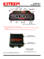
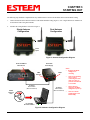
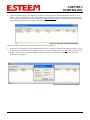
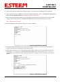
CHAPTER 3
STARTING OUT
OVERVIEW
Most configuration of the ESTeem Model 195Eg is completed using the internal Web interface (discussed in detail in Chapter 4),
but to access the modem through a web browser requires first setting the TCP/IP address. The TCP/IP address (IP address) is set at
the factory for a static Class B (172.16.xxx.xxx - Mask 255.255.0.0) and listed on the ESTeem documentation. If this IP address
does not match your network configuration, you will need to use either the ESTeem 195E Discovery program or the RS-232
interface to set the IP address in the 195Eg.
QUICK START GUIDE
A printed copy of the Model 195Eg Quick Start Guide was provided in the documentation package that arrived with your new
ESTeem 195Eg. This guide is an abbreviated step-by-step procedure on configuration of the 195Eg for most Ethernet bridging and
Access Point applications. A copy of the Quick Start Guide is provided in Appendix G of this User’s Manual for convenience.
MODEL 195Eg HARDWARE LAYOUT
Unpack the ESTeem Model 195Eg shipping boxes and locate the items contained below for initial configuration. Take a few
minutes to inventory your equipment before you proceed. Report any missing or damaged items to Customer Support (509-7359092) as soon as possible.
Each node in your ESTeem Model 195Eg’s network may have different hardware components based upon the final installation
location (i.e Outdoor, Indoor, Point-to-point or Muti-Point). Antenna types, cable lengths, power supplies may be different, but the
following items will be required for basic setup:
Model 195Eg
AA109 Resource Disk
Antenna
(AA01S Displayed)
(2) Ethernet Cables
Power Supply
(AA175 Displayed)
Serial Interface Cable
(AA6021.1)
Note: Your accessory model numbers may vary from the above, but you will need to locate each of above items to continue
configuration.
Revised: 27 Oct 08
3-1
EST P/N AA107G
CHAPTER 3
STARTING OUT
(Optional)
Second
RS-232
Ethernet
Reset Switch Data Port
Port
Status
LED
Receive
LED
Transmit
LED
RS-232
Configuration
RJ-45 10/100BaseT
Ethernet Port
Aux Power
LED
12 VDC Input
(Auxiliary
Connector )
Figure 1: 195Eg Front Panel Overview
Power over
Ethernet LED
Notes:
• There is no Power On/Off switch on the Model 195Eg.
• Attach the programming Cable to the RS-232 Programming Port and the Patch Cable between the Power Supply and
Ethernet port.
• One word of caution, always attach an antenna to Port A (Figure 2) on the Model 195Eg before power up.
Antenna Port A
(Single Receive Antenna)
Antenna Port B
(Dual Receive Antennas)
Antenna Connectors
(TNC Female-RP)
Figure 2: 195Eg Antenna Overview
MODEL 195Eg HARDWARE CONFIGURATION
Revised: 27 Oct 08
3-2
EST P/N AA107G
CHAPTER 3
STARTING OUT
The following steps should be completed before any modifications are made to the IP address in the ESTeem Model 195Eg:
1.
Connect the antenna to the antenna connector on the ESTeem Model 195Eg (Figure 3). For a single antenna use Antenna Port
A and connect both if using dual antennas.
2.
Assemble the 195Eg hardware as shown in Figure 4.
Single Antenna
Configuration
Dual Antenna
Configuration
Leave
Open
Figure 3: Antenna Configuration Diagram
RJ-45 10/100BaseT
Ethernet Port
AA175 PoE
Power Supply
LAN In
PWR
Data Out
10/100BaseT
Ethernet Cable
(Patch or Cross Over)
Notes:
• Configure the Model
195Eg prior to
mounting.
•
Some of the following
steps, such as
connecting the serial
cable, are easier to
perform if the ESTeem
is accessible.
•
Please attach an
antenna to the Model
195Eg before power up.
•
There is no Power
On/Off switch on the
Model 195Eg.
10/100BaseT
Ethernet Cable
(Patch or Cross Over)
AA109
Resource
Disk
PC with Web
Browser Software
Figure 4: Hardware Configuration Diagram
Revised: 27 Oct 08
3-3
EST P/N AA107G
CHAPTER 3
STARTING OUT
3.
Complete the following System Configuration Table. The Model 195Eg will link to other Model 195Eg’s on the network
via the WLAN Media Access Control (MAC) address found on the bottom of the case. This MAC address is six
hexadecimal digits separated by colons and is configured at the factory. Every MAC address in the world is unique and
can not be changed. Complete the following chart to aid in your when defining modes of operation and repeater routes.
Modem_ID(Name)
/Operating Mode
Serial Number
IP Address
Ethernet MAC
WLAN MAC
Example Modem 1
AP_Bridge
E-14001
172.16.8.101
00:04:3f:00:01:01
00:04:3f:00:01:02
Revised: 27 Oct 08
3-4
EST P/N AA107G
CHAPTER 3
STARTING OUT
ESTEEM DISCOVERY UTILITY
The ESTeem Discovery Utility will allow you to
configure the IP address on the Model 195Eg to match
your network. Install the Discovery Utility on your
computer by inserting the Resource Disk in your CD
drive.
Note: The ESTeem Resource Disk is stand-alone copy of
the ESTeem Web site (Figure 5). Navigation of the
Resource Disk is as simple as using your web browser.
All technical documentation, User’s Manuals and the
ESTeem Utility Program is available on the disk.
1.
Place the ESTeem Utility CD in your CD-ROM
drive. The CD will auto load the ESTeem main
page
Figure 5: ESTeem Resource Main Page
Note: If the page does not auto load, open your web browser and set your address line to D:\index.html (Where D: is the
drive letter for your CD-ROM drive).
2.
From the Main Page select ESTeem Utilities and click on ESTeem Discovery Utility (Figure 6).
Figure 6: Discovery Utility Download
Note: This program is saved in a compressed file format. Microsoft Windows XP® will open the file directly, but other
operating systems will require a common compression program such as WinZip available for download at
http://www.winzip.com
3.
Double click on the 195EgiscoverySetup.exe file listed in the window to install the program.
Revised: 27 Oct 08
3-5
EST P/N AA107G
CHAPTER 3
STARTING OUT
4.
Connect the Model 195Eg to your computer either direct to the Ethernet card or through a HUB/Switch using a CAT-5e
Ethernet cable. The Ethernet port on the 195Eg supports Auto-Negotiation so either a patch cable or crossover cable will
work. Open the ESTeem Discovery Program and press the Discover Modems button. The Model 195Eg will be displayed
in the program by the Ethernet MAC address and Current IP Address (Figure 7).
Figure 7: Discovery Program Main Page
Note: The SSID and Mode of Operation will be adjusted later in the configuration.
5.
Double-click on the 195Eg you want to program and the Configure IP Address window will be displayed (Figure 8). Enter
an IP address and Subnet Mask for the 195Eg that matches your network subnet and press the OK button to save this to the
ESTeem. You will receive notification that the Configuration was Successful and the 195Eg will reboot. Proceed to
ESTeem Setup in Chapter 4.
Figure 8: Change IP Address Window
Revised: 27 Oct 08
3-6
EST P/N AA107G
CHAPTER 3
STARTING OUT
USING THE RS-232 INTERFACE
Any terminal emulation program that can run with VT100 emulation can be used for this configuration of the ESTeem. Most
Windows users will probably use either Hyper Terminal or the Terminal Emulation in the ESTeem Utility program. Configure
your RS-232C port for a Baud Rate to 38,400, Data Bits to 8, Parity to None, Stop Bits to 1 and Handshaking to None and set
the Emulation type to VT100. Once your ESTeem has an IP address, you can attach the ESTeem to your network and use the
Web Server for further programming.
Programming Using the RS-232 Port
1. When configuring the Model 195Eg for the first time you can use the ESTeem RS-232C Configuration Menu to setup the basic
operating parameters such as assigning the IP Address, IP Net Mask, and Gateway IP Address.
2. Connect the serial cable (EST P/N: AA0621.1) between the RS-232 connector (RJ-45) on the Model 195Eg’s programming
port to the serial port on the computer.
3.
Any terminal emulation program can be used for the configuration of the Model 195Eg. Most users will use either the
Terminal Emulation section of the ESTeem Utility Program or Hyper Terminal in Windows. Configure your RS-232C port for
a Baud Rate to 38,400, Data Bits to 8, Parity to None, Stop Bits to 1, use No Handshaking (Flow Control) and set the
Terminal to VT100 emulation.
4. Plug the Model AA175 power supply into a wall socket and connect an Ethernet patch cable from the Model 195Eg Ethernet
port to the J1 (Data&PWR) port on the power supply (Figure 4). The Power over Ethernet (POE) LED on the front of the
ESTeem should be illuminated.
5. If your computer is configured properly, you will see the ESTeem Model 195Eg booting sequence on your Terminal Emulation
program. Once the ESTeem boot sequence is complete (approximately 45 seconds) you will receive this message:
“Please press Enter to active this console.”
If you don’t see this message press the Reset button on the front panel of the Model 195Eg and/or check the programming of
your RS-232 port.
6. Press the Enter key and you will be at the Configuration Menu 195Eg login prompt. See Figure 9.
7. To enter the Model 195Eg Main Menu you will need to log into the system with a login name and password.
Figure 9: RS-232 Port Log-in Screen
Revised: 27 Oct 08
3-7
EST P/N AA107G
CHAPTER 3
STARTING OUT
8. If this is not the first time configuration of the Model 195Eg, see your network systems administrator for the password.
9. At the 195Eg login prompt type admin for the login name and press the Enter key (<Enter>). The login name is defined at the
factory and is not changeable by the user. Note that all characters are lower case.
10. If this is the first time the Model 195Eg has been programmed or the Password was not changed from the factory default
values, the factory default password is also admin. Enter admin for the password and press the Enter key (<Enter>).
Note: All characters are lower case.
The ESTeem Configuration Welcome Screen (Figure 10) will now be displayed.
Figure 10: RS-232 Welcome Screen
11. To set the IP address in the ESTeem 195Eg, type the letter A and press the Enter key. Enter the value for the IP address,
Netmask and default route and pressing the Enter key after each entry.
12. After the basic parameters have been entered into the Model 195Eg you will need to commit the changes to the Model
195Eg (Figure 11). Press the C key and then the Enter and the changes will be saved to flash memory. You can use
programming features in the ESTeem Web Configuration Manager to configure the unit for your application. Proceed to
Chapter 4.
Figure 11: RS-232 Welcome Screen
Revised: 27 Oct 08
3-8
EST P/N AA107G