1
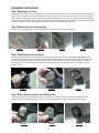
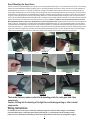
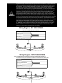
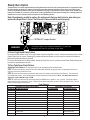
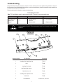
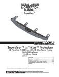
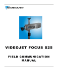
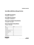
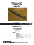
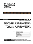
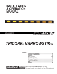
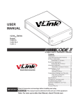
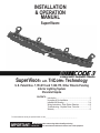
INSTALLATION
& OPERATION
MANUAL
SuperVisor®
SuperVisor® with TriCore® Technology
U.S. Patent Nos. 7,153,015 and 7,300,175, Other Patents Pending
Interior Lighting System
Chevrolet Impala
CONTENTS:
Introduction............................................................................2
Unpacking & Pre-Installation.................................................2
Installation & Mounting.......................................................3-4
Wiring Instructions - Flash Pattern Selection ....................4-6
Troubleshooting - Exploded View - Parts List........................7
Warranty................................................................................8
For future reference record your product's serial no. here __________________________________________
IMPORTANT: INSTALLER:
Read all instructions and warnings before installing and using.
This manual must be delivered to the end user of this equipment.
Introduction
The SuperVisor® with TriCore® Technology is an interior lighting system that fits in the visor area near the top of the windshield. The
SuperVisor has room for up to eight TriCore light heads.
Product Features
TriCore light head options: Red, Blue, Amber, and White------------------Flashing or Steady Burn Control
Size: 44.30" long x 1.71" tall x 6.78" deep--------------------------------------Weight: 7.5 lbs
warning!
The use of this or any warning device does not ensure that all drivers can or will observe or react to an
emergency warning signal. Never take the right-of-way for granted. It is your responsibility to be sure you can
proceed safely before entering an intersection, driving against traffic, responding at a high rate of speed, or
walking on or around traffic lanes. The effectiveness of this warning device is highly dependent upon correct
mounting and wiring. Read and follow the manufacturer’s instructions before installing or using this device. The
vehicle operator should insure daily that all features of the device operate correctly. In use, the vehicle operator
should insure the projection of the warning signal is not blocked by vehicle components (i.e.: open trunks or
compartment doors), people, vehicles, or other obstructions. This equipment is intended for use by authorized
personnel only. It is the user’s responsibility to understand and obey all laws regarding emergency warning
devices. The user should check all applicable city, state and federal laws and regulations. Code 3, Inc., assumes
no liability for any loss resulting from the use of this warning device. Proper installation is vital to the performance
of this warning device and the safe operation of the emergency vehicle. It is important to recognize that the
operator of the emergency vehicle is under psychological and physiological stress caused by the emergency
situation. The warning device should be installed in such a manner as to: A) Not reduce the output performance
of the system, B) Place the controls within convenient reach of the operator so that he can operate the system
without losing eye contact with the roadway. Emergency warning devices often require high electrical voltages
and/or currents. Properly protect and use caution around live electrical connections. Grounding or shorting of
electrical connections can cause high current arcing, which can cause personal injury and/or severe vehicle
damage, including fire. Any electronic device may create or be affected by electromagnetic interference. After
installation of any electronic device operate all equipment simultaneously to insure that operation is free of
interference. Never power emergency warning equipment from the same circuit or share the same grounding
circuit with radio communication equipment. All devices should be mounted in accordance with the manufacturer's
instructions and securely fastened to vehicle elements of sufficient strength to withstand the forces applied to the
device. Driver and/or passenger air bags (SRS) will affect the way equipment should be mounted. This device
should be mounted by permanent installation and within the zones specified by the vehicle manufacturer, if any.
Any device mounted in the deployment area of an air bag will damage or reduce the effectiveness of the air
bag and may damage or dislodge the device. Installer must be sure that this device, its mounting hardware and
electrical supply wiring does not interfere with the air bag or the SRS wiring or sensors. Mounting the unit inside
the vehicle by a method other than permanent installation is not recommended as unit may become dislodged
during swerving, sudden braking or collision. Failure to follow instructions can result in personal injury. PROPER
INSTALLATION COMBINED WITH OPERATOR TRAINING IN THE PROPER USE OF EMERGENCY WARNING
DEVICES IS ESSENTIAL TO INSURE THE SAFETY OF EMERGENCY PERSONNEL AND THE PUBLIC.
Unpacking & Pre-installation
Carefully remove the SuperVisor and place it on a flat surface, taking care not to scratch the lenses or damage the cable coming out of
the top. Examine the unit for transit damage, broken lamps, etc. Report any damage to the carrier and keep the shipping carton.
Standard light bars are built to operate on 12 volt D.C. negative ground (earth) vehicles. If you have an electrical system other than 12
volt D.C. negative ground (earth), and have not ordered a specially wired light bar, contact the factory for instructions.
Test the unit before installation. To test, touch the black wire to the ground (earth) and the other wires to +12 volts D.C., in accordance
with the instructions attached to the cable (an automotive battery is preferable for this test). A battery charger may be used, but note that
some electronic options may not operate normally when powered by a battery charger. If problems occur at this point, contact the factory.
Note: Before beginning the installation process, be absolutely certain
that the Light Bar functions as desired (See page 6 for options)!
warning!
Utilizing non-factory supplied screws and/or mounting brackets and/or the improper
number of screws may result in loss of warranty coverage on the equipment.
Mounting Hardware - All mounting hardware is packed in a small bag inside the main carton. There are four brackets used to mount
the SuperVisor to the vehicle. These are discussed in detail later.
2
Installation Instructions
Step 1 Removing Sun Visors
To remove the Chevy Impala's driver and passenger sun visors first identify each visor with tape or other marking to indicate driver from passenger; they are not identical. To remove the plastic visor clip cover, pry the cover apart at the thin slit (See Figure 1) with a thin instrument
like a putty knife and pull the cover down and away from the headliner at the same time (See Figure 2). There are three screws that hold the
pivotal arm of the sun visor to the headliner. Remove the three sun visor mounting screws using a small #20 Torx screwdriver starting with the
lower screw as shown in Figure 3. Then rotate the sun visor over to expose and remove the other two screws.
Step 2 Remove the visor retaining clips
Remove the sun visor retaining clips, unscrew the single Torx screw holding it in place as shown in Figure 4.
Figure 1
Figure 2
Figure 3
Figure 4
Step 3 Attach the pivot arm brackets
Attach the supplied outer brackets noting the difference between passenger and driver side (see Figure 5 -Driver side shown). Rotate
the Pivot Arm on the Driver's side sun visor and verify the orientation of the Outer Bracket as shown in Figure 6. Position the Driver's Side
pivot arm and loosely attach the first Torx screw as shown in Figure 7. Next, move the sun visor over in order to gain access to loosely
attach the other two Torx screws. Repeat this operation for the Passenger side Pivot arm and outer bracket. Do not tighten any of the
screws at this time.
Figure 5
Figure 6
Figure 7
Step 4 Attach brackets to sun visor retaining clips
Place the inner bracket on the retaining clip as shown in Figures 8 and 9. Loosely attach the inner bracket and retaining clip to the
headliner with the Torx screw as illustrated in Figure 10. Do not tighten these screws at this time (they should be barely started).
Figure 8
Figure 9
3
Figure 10
Step 5 Mounting the SuperVisor®
Remove the small Torx screw holding the rear view mirror to it's mounting bracket (See Figure 11), then push the mirror up and off of the mounting
bracket. Pinch the small terminal retaining clip (See Figure 12) and unplug the power wire to free the mirror. Once all four sun visor brackets are
attached and the rear view mirror is removed, the SuperVisor is ready to be installed. Route the power cable across the top and along the passenger side of the SuperVisor, then route it through the notch provided on the front and passenger side front of the outer panel. This will prevent it
from interfering with the head liner or the windshield during installation. Carefully move the SuperVisor into position by tilting one end up as shown
in Figure 13, then swing the other end up into position being careful not to scratch the Impala's plastic corner post covers. Line up the mounting
holes in the Inner Mounting Brackets with the threaded holes in the SuperVisor and loosely thread the supplied 1/4"-20 bolts and internal tooth lock
washers into the holes in the SuperVisor's Outer Panel as shown in Figure 14 (Note: It is helpful to have an assistant pull down on the Inner
Mounting Brackets while you push up on the SuperVisor to help in aligning the holes). Tighten the two center inner Torx mounting screws as
shown in Figure 15. Tighten the two 1/4-20 bolts at the Inner Mounting Brackets (see Figure 16). Line up the mounting holes in the outer mounting brackets with the threaded holes in the SuperVisor and thread the supplied 1/4"-20 bolts and internal tooth lock washers into the SuperVisor's
Outer Panel (see Figure 17). Tighten the three Torx screws in each of the two outer Pivot Brackets as shown in Figure 18. While pushing up on the
SuperVisor's Outer Panel, tighten the 1/4-20 bolts in the Outer Mounting Brackets (see Figure 19), then Replace the Plastic Visor Pivot Bracket
Covers.Plug the power wire back into the rear view mirror, reattach it, and retighten the Torx screw to secure the rear view mirror.
Figure 14
Figure 17
RETAINING CLIP___
__
Figure 11
__
__
__
__
__
__
__
_____
___
Figure 12
Figure 15
Figure 18
Figure 13
Figure 16
Figure 19
The bracket fasteners make excellent hard mounting points for radar guns and video
cameras etc.
Caution: Drilling into the housing of the light bar could damage wiring or other internal
components.
Wiring Instructions
It is advisable to leave an extra loop of cable when installing the light bar to allow for future changes or reinstallations.
Connect the black lead to a solid frame ground (earth), preferably the (-) or ground (earth) side of the battery, and the
power wire to the +12V terminal of the battery. Connect the remaining wires as shown in the wiring diagrams on page 5.
4
Warning!
Larger wires and tight connections will provide longer service life for components. For high current wires it
is highly recommended that terminal blocks or soldered connections be used with shrink tubing to protect
the connections. Do not use insulation displacement connectors (e.g. 3M® Scotchlock type connectors).
Route wiring using grommets and sealant when passing through compartment walls. Minimize the
number of splices to reduce voltage drop. High ambient temperatures (e.g. under hood) will significantly
reduce the current carrying capacity of wires, fuses, and circuit breakers. Use "SXL" type wire in engine
compartment. All wiring should conform to the minimum wire size and other recommendations of the
manufacturer and be protected from moving parts and hot surfaces. Looms, grommets, cable ties, and
similar installation hardware should be used to anchor and protect all wiring. Fuses or circuit breakers
should be located as close to the power takeoff points as possible and properly sized to protect the wiring
and devices. Particular attention should be paid to the location and method of making electrical connections
and splices to protect these points from corrosion and loss of conductivity. Ground terminations should
only be made to substantial chassis components, preferably directly to the vehicle battery. The user should
install a fuse sized to approximately 125% of the maximum Amp capacity in the supply line to protect
against short circuits. For example, a 30 Amp fuse should carry a maximum of 24 Amps. DO NOT USE
1/4" DIAMETER GLASS FUSES AS THEY ARE NOT SUITABLE FOR CONTINUOUS DUTY IN SIZES
ABOVE 15 AMPS. Circuit breakers are very sensitive to high temperatures and will "false trip" when
mounted in hot environments or operated close to their capacity.
Wiring Diagram - NO TAKE DOWNS
FUSE WITH CUSTOMER SUPPLIED 10 AMP FUSE
BLACK (GND)
BLUE (LEVEL 1)
ORANGE (LEVEL 2)
YELLOW (LEVEL 3)
RED (POWER)
WHITE (DIMMING)
GREEN (PATTERN SELECT)
Wiring Diagram - WITH TAKE DOWNS
NOTE: FOR SUPERVISORS WITH TAKE DOWN OPTION CONTROL WIRES ARE AS SHOWN BELOW
THE TAKEDOWN STEADY(YELLOW) WIRE WILL OVERRIDE THE TAKEDOWN FLASH (ORANGE) WIRE.
BLACK (GND)
BLUE (LEVEL 1)
ORANGE (TAKEDOWN FLASH)
YELLOW (TAKEDOWN STEADY)
RED (POWER)
WHITE (DIMMING)
GREEN (PATTERN SELECT)
5
Steady Burn Option
The SuperVisor® can operate Light Head #2 (second Light Head from the driver side) in steady burn mode. To change the #2 Light
Head from flashing to steady burn, remove the mounting screws that attach the SuperVisor's Cover to the Outer Panel to gain
access to the printed circuit board inside (see the exploded view on page 7). Move the Shunt Option Jumper on the printed circuit
board to the "OPTION JP1" position as shown below. The #2 Light Head should now operate in steady burn. Carefully replace the
SuperVisor's Cover over the Outer Panel and replace the Cover Mounting Screws.
Note: Be extremely careful to replace the wiring such that you don't pinch a wire when you
replace the SuperVisor's Cover. Test the unit to be sure that it works properly.
<---------------"OPTION JP1" Jumper Position
Warning!
This Product contains high intensity TriCore® devices. To prevent eye
damage, DO NOT stare into light beam at close range.
TriCore® Light Head Flash Pattern
To change the flash patterns of the TriCore Light Heads, activate the Light Bar in Level 1 and then momentarily touch the Green
(Pattern Select) wire to +power. Repeating this procedure allows the operator to cycle through the numerous flash patterns
offered until the desired pattern is achieved.
To reset the flash patterns to the factory default, activate the Light Bar in Level 1 and then hold the Green (Pattern Select) wire
to +power for approximately 4 seconds.
TriCore Take Down Flash Pattern
Selecting Flash Patterns: The Take Down Lights can be programmed to flash at different rates.
STEP 1: Power-up the light bar. Select the Take Down Flash Mode (ORANGE) by applying +power. Programming will not work if
more than one function is selected at a time.
STEP 2: Observe the flash pattern and determine which pattern is in operation (see Take Down Flash Patterns). This table shows
the available flash patterns. Once the flash pattern has been determined, proceed to Step 3. NOTE: The default flash pattern for
Take Down Lights is Medium Single 115FPM.
STEP 3: Scroll to the next pattern by momentarily holding the GREEN wire to +power for ~one (1) second. The light bar will stop
flashing when the wire is connected to +power. Release the wire and the next pattern as listed in Table 5 will begin to flash. The new
pattern is automatically stored each time.
STANDARD LIGHT HEAD FLASH PATTERNS
Flash Patterns
TAKE DOWN FLASH PATTERNS
PATTERN NO PATTERN DESCRIPTION
PATTERN NUMBER
PATTERN DESCRIPTION
1
FAST ALTERNATING QUAD FLASH 100ms/25ms
1
FAST QUAD 80FPM
2
PICKET FENCE SINGLE FLASH 200ms/25ms
2
SLOW QUAD 60FPM
3
ALTERNATING SINGLE FLASH 200ms/25ms
3
4
PICKET FENCE QUAD FLASH 100ms/25ms
4
5
PICKET FENCE SIX FLASH 75ms/25ms
5
SLOW SINGLE 60FPM
6
SLOW ALTERNATING QUAD FLASH 150ms/50ms
6
FAST DOUBLE 115FPM
7
SLOW ALTERNATING SIX FLASH 125ms/25ms
7
SLOW DOUBLE 60FPM
8
FAST ALTERNATING SIX FLASH 75ms/25ms
8
FAST SIX 80FPM
9
VARIABLE RATE PICKET FENCE, SINGLE FLASH
9
SLOW SIX 60FPM
10
ALTERNATING QUAD FLASH, 80 FPM, NFPA COMPLIANT
10
VARIABLE RATE SINGLE
11
CYCLE FLASH
11
NFPA QUAD 75FPM
12
SIMULTANEOUS QUAD FLASH, 75 FPM, NFPA COMPLIANT
12
CYCLE FLASH
6
FAST SINGLE 375FPM
FACTORY DEFAULT
MEDIUM SINGLE 115FPM
Troubleshooting
All SuperVisors® are thoroughly tested prior to shipment. However, should you encounter a problem during installation or during the
life of the product, follow the guide below for information on repair and troubleshooting. Additional information may be obtained from
the factory technical help line at 314-996-2800.
Follow the guide below for information on repair and troubleshooting.
TROUBLESHOOTING GUIDE
Note: TriCore® Modules must be replaced as a module. There are no user serviceable parts.
PROBLEM
QUESTIONS
TriCore Module not
operating when
powered.
POSSIBLE CAUSE
SOLUTION
a.Bad power/ground
connection.
b.Defective module.
N/A
a. Fix connection.
b. Replace module
Any disassembly of any of the TriCore light heads will result in loss of warranty coverage on the
equipment.
warning!
Parts List
2
3
4
5
6
1
7
8
Reference Number 1
Part Description
Outer Mtg. Brkt. Impala Pass Side
2
3
4
5
6
7
8
Part Number
T14713
Cover T15085
Inner Mtg. Brkt. Impala T14700
Light Blocking Brkt. Impala Blank Brkt. Crown Vic Outer Mtg. Brkt. Impala Drivr Side
7
T15086
T15056
T14714
Outer Panel
TriCore® Module
T15084
Contact Code 3, Inc for P/N
WARRANTY
This product with TriCore® Technology was tested and found to be operational at the time of manufacture.
Provided this product is installed and operated in accordance with the manufacturer's recommendations, Code
3®, Inc. warrants all parts and components (with the exception of all incandescent and halogen bulbs) of the
product to be free of defects in material and workmanship for a period of one (1) year and TriCore light heads
for a period of five (5) years from the date of purchase. This Warranty excludes normal wear & tear. Units
demonstrated to be defective within the warranty period will be repaired or replaced at the factory service
center at no cost. Code 3, Inc. will return the repaired product with transportation cost prepaid. Code 3, Inc.
assumes no liability for expenses incurred in the packaging, handling, and shipping of the product to the Factory
Technical Service Department for repair. For in-warranty product return authorization, questions regarding
product warranty coverage or questions regarding out-of-warranty repair quotes, contact the Factory Technical
Service Department.
The TriCore light heads are sealed as part of the quality control process. This Warranty is void if, in the
judgment of Code 3, Inc. (1) an attempt has been made to break the light head seal or repair the light head,
and/or (2) the product has been used with inappropriate or inadequate wiring or circuit protection, and/or (3)
the product has failed as a result of abuse or unusual use and/or accidents.
Code 3, Inc. shall in no way be liable for any other damages relating to the
product including but not limited to consequential, incidental, indirect or special damages or lost profits or revenue; nor any expenses incurred in the removal and/or re-installation of products requiring service and/or repair.
EXCEPT AS SET FORTH ABOVE, CODE 3, INC. MAKES NO OTHER EXPRESS OR IMPLIED
WARRANTIES WHATSOEVER, INCLUDING, WITHOUT LIMITATION, WARRANTIES OF FITNESS FOR A
PARTICULAR PURPOSE OR MERCHANTABILITY, WITH RESPECT TO THIS PRODUCT.
NEED HELP? Call our Technical Assistance HOT LINE ‑ (314) 996-2800
PRODUCT RETURNS
If a product must be returned for repair or replacement*, please contact our factory to obtain a Return
Goods Authorization Number (RGA number) before you ship the product to Code 3, Inc. Write the RGA number
clearly on the package near the mailing label. Be sure you use sufficient packing materials to avoid damage to
the product being returned while in transit.
*Code 3, Inc. reserves the right to repair or replace at its discretion. Code 3, Inc. assumes no responsibility or liability for expenses incurred for the removal and /or
reinstallation of products requiring service and/or repair.; nor for the packaging, handling, and shipping: nor for the handling of products returned to sender after the service has been
rendered.
Code 3®, Inc.
10986 N. Warson Road
St. Louis, Missouri 63114-2029—USA
Ph. (314) 426-2700 Fax (314) 426-1337
www.code3pse.com
Revision 4, 01/10 - Instruction Book Part No. T15075
©2010 Public Safety Equipment, Inc. Printed in USA
Code 3 is a registered trademark of Code 3, Inc. a subsidiary of Public Safety Equipment, Inc.
8