1
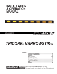
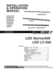
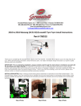
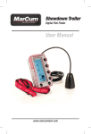
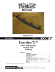
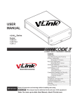
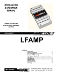
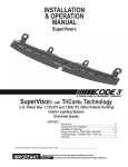
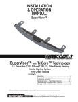
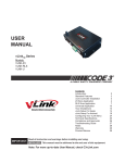
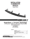
INSTALLATION
& OPERATION
MANUAL
ASL1060H
ASLSP10H
ASLC1060H
LARGE LED
NARROWSTIK™
Contents:
Introduction (with warnings) .............................................. 2
Models ................................................................................ 2
Unpacking & Pre-installation ............................................... 2
Installation & Mounting ........................................................ 2
Assembly Diagrams ............................................................ 3
Wiring Instructions .......................................................... 4-10
Specifications .................................................................... 10
Maintenance ...................................................................... 10
Troubleshooting ................................................................ 11
Notes ................................................................................. 11
Warranty ............................................................................ 12
IMPORTANT:
Read all instructions and warnings before installing and using.
INSTALLER: This manual must be delivered to the end user of this equipment.
1
Introduction
The Large LED Narrowstik® is a traffic directing device that will mount in many locations. The Large LED Narrowstik is a series of
lights that point traffic away from the scene of an accident or work site and utilizes state-of-the-art High-Flux L.E.D. lightheads. These
lightheads last longer and use much less current than standard incandescent lamps.
!
WARNING!
The use of this or any warning device does not insure that all drivers can or will observe or react
to an emergency warning signal. Never take the right-of-way for granted. It is your responsibility
to be sure you can proceed safely before entering an intersection, driving against traffic,
responding at a high rate of speed, or walking on or around traffic lanes.
The effectiveness of this warning device is highly dependent upon correct mounting and wiring.
Read and follow the manufacturer’s instructions before installing or using this device. The
vehicle operator should insure daily that all features of the device operate correctly. In use, the
vehicle operator should insure the projection of the warning signal is not blocked by vehicle
components (i.e.: open trunks or compartment doors), people, vehicles, or other obstructions.
This equipment is intended for use by authorized personnel only. It is the user’s responsibility
to understand and obey all laws regarding emergency warning devices. The user should check
all applicable city, state and federal laws and regulations.
Public Safety Equipment, Inc., assumes no liability for any loss resulting from the use of this
warning device.
Proper installation is vital to the performance of this warning device and the safe operation of
the emergency vehicle. It is important to recognize that the operator of the emergency vehicle
is under psychological and physiological stress caused by the emergency situation. The
warning device should be installed in such a manner as to: A) Not reduce the output performance
of the system, B) Place the controls within convenient reach of the operator so that he can
operate the system without losing eye contact with the roadway.
Emergency warning devices often require high electrical voltages and/or currents. Properly
protect and use caution around live electrical connections. Grounding or shorting of electrical
connections can cause high current arcing, which can cause personal injury and/or severe
vehicle damage, including fire.
PROPER INSTALLATION COMBINED WITH OPERATOR TRAINING IN THE PROPER USE
OF EMERGENCY WARNING DEVICES IS ESSENTIAL TO INSURE THE SAFETY OF
EMERGENCY PERSONNEL AND THE PUBLIC.
Models:
1: ASL1060H: Standard LED 10-position Amber 60" Narrowstik
2: ASLSP10H: Split LED 10-position Amber 33" (each) Narrowstik
3: ASLC1060H: Standard LED 10-position Amber 60" LC-Stik
Unpacking & Pre-installation
After unpacking the items, carefully inspect the unit and its associated parts for any damage that may have
been caused in transit. Report any damage to the carrier immediately.
Installation & Mounting
The Large LED Narrowstik was designed for mounting with a minimum four fasteners. The outer covers at each arrow wing must be
removed since they conceal the prepunched mounting holes for a more aesthetically pleasing appearance. Three #6 x .5" sheet metal
screws attach the covers and may be removed with a T-15 Torx screwdriver. (See Figure 1) The system is designed to use 3/8"-16
fasteners (included in the parts bag, see Figure 2 for details) for attaching the Narrowstik frame to the customer’s mounting surface. The
Split Narrowstik assembly is mounted in a similar fashion but uses two ¼”-20 fasteners (included in the parts bag) to attach each end flange
and complete the mounting. Attachment holes may be drilled anywhere along the main horizontal frame to attach the Narrowstik assembly
for a variety of mounting applications. Care should be taken to first remove the outer cover and be certain that no wiring is damaged during
the drilling and mounting process. The plastic caps (included in the parts bag) may be installed in the prepunched mounting holes if not
used to install the Narrowstik.
2
Figure 1
Figure 2
3/8" LOCK WASHER
3/8"-16 HEX NUT
3/8" FLAT WASHER
3/8" FLAT WASHER
3/8"-16 X 1-1/4" HEX BOLT
3
Wiring Instructions
Refer to the manual packaged with the 8 Output LED Narrowstik® Controller for detailed
control head wiring, installation and operation instructions.
!
WARNING!
Larger wires and tight connections will provide longer service life for components. For high current wires it is highly
recommended that terminal blocks or soldered connections be used with shrink tubing to protect the connections. Do
not use insulation displacement connectors (e.g. 3M® Scotchlock type connectors). Route wiring using grommets and
sealant when passing through compartment walls. Minimize the number of splices to reduce voltage drop. High ambient
temperatures (e.g. underhood) will significantly reduce the current carrying capacity of wires, fuses, and circuit breakers.
Use "SXL" type wire in engine compartment. All wiring should conform to the minimum wire size and other
recommendations of the manufacturer and be protected from moving parts and hot surfaces. Looms, grommets, cable
ties, and similar installation hardware should be used to anchor and protect all wiring.
Fuses or circuit breakers should be located as close to the power takeoff points as possible and properly sized to protect
the wiring and devices.
Particular attention should be paid to the location and method of making electrical connections and splices to protect these
points from corrosion and loss of conductivity.
Ground terminations should only be made to substantial chassis components, preferably directly to the vehicle battery.
The user should install a fuse sized to approximately 125% of the maximum Amp capacity in the supply line to protect
against short circuits. For example, a 30 Amp fuse should carry a maximum of 24 Amps.
DO NOT USE 1/4" DIAMETER GLASS FUSES AS THEY ARE NOT SUITABLE FOR CONTINUOUS DUTY IN
SIZES ABOVE 15 AMPS.
Circuitbreakers are very sensitive to high temperatures and will "false trip" when mounted in hot environments or
operated close to their capacity.
1. After installing the Large LED Narrowstik , route the 11-wire cable into the vehicle to where the control head will be mounted.
2. Cut the cable to length and strip back the cable insulation on the 11- wire cable.
3. Connect the red and red/white wires in, the 11- wire cable, to the positive (+12V) side of the battery through a user supplied
15 amp fuse or breakering an 16 gauge minimum wire or larger.
4. Route a minimum 16 gauge black wire to the battery negative ( ground) (earth). Use the 1/4" insulated quickslide located in
control head parts bag and connect the black 16 gauge wire control head.
5. Remove the 14- position terminal plug from the back of the control head. Connect the the remaining wires, in the 11-wire
cable, to the plug as shown in Figure 5, page 5. Connect power to the control head. See control head manual for auxillary
wire functions.
Note: When installing the Large LED Narrowstik as a Front Facing system, or if it is desired to have the cable exit from
the Passenger side, the LED module control wires will be reversed. See Figure 6, page 6, for details.
6. Check all connections for frayed or shorted wires. Insert the plug back into the Narrowstik control head.
WARNING!
!
This Product contains high intensity LED devices. To prevent eye damage, DO NOT
stare into light beam at close range.
4
Bl
Br
ue
Yellow
Grey
Green
Violet
ow
n
Tan Orange
Input Cable
Bl
ue
o
Br
STANDARD REAR FACING MOUNTING
DRIVER SIDE
wn
PASSENGER SIDE
11-Wire Cable Wire Designations-Standard Rear Facing Mounting
RED, RED/WHITE
Large L.E.D. Narrowstik® (+12V) wires
WHITE
DIM Control wire
BROWN
ORANGE
TAN
INDIVIDUAL
VIOLET
L.E.D. MODULE CONTROL WIRES
GREEN
(SEE FIGURE 5)
GREY
YELLOW
BLUE
UE
B L LOW
L
YE E Y
GR EEN
GR ET
OL
VI N
GE
TA AN N
OR
BR
ITE
OW
WH
CO
NT
HD
PW
Rear Facing System Wiring
R
(+1
2V
)
Figure 5
Large LED Narrowstik wire designations for standard rear facing mounting
5
n
Bl
ow
ue
Br
OPTIONAL FRONT FACING MOUNTING
Yellow
Grey
Green
Violet
Tan
Orange
n
Input Cable
Br
ue
ow
Bl
PASSENGER SIDE
DRIVER SIDE
N
OW E
BR ANG
OR N
T A LET
O
VI EEN
GR EY
W
G R LLO
YE U E
BL
WH
ITE
CO
NT
HD
PW
Front Facing System Wiring
R
(+1
2V
)
Figure 6
Large LED Narrowstik wire designations for optional front facing mounting
Large Split LED Narrowstik®
1. After installing the Large Split LED Narrowstik, route the two (2) 11-wire cables into the vehicle to where the control head
will be mounted.
2. Cut the cables to length and strip back the cable insulation on the 11- wire cables.
3. Connect the red and red/white wires in both 11- wire cables, to the positive (+12V) side of the battery through a user
supplied 15 amp fuse or breakering an 16 gauge minimum wire or larger.
4. Route a minimum 16 gauge black wire to the battery negative ( ground) (earth). Use the 1/4" insulated quickslide located in
control head parts bag and connect the black 16 gauge wire control head.
5. Remove the 14 position terminal plug from the back of the control head. Connect the the remaining wires, in the 11-wire
cables, to the plug as shown in Figure 7, page 7. Connect power to the control head. See control head manual for auxillary
wire functions.
Note: When installing the Large Split L.E.D. Narowstik as a Front Facing system, or if it is desired to have the cable exit
from the Passenger side, the L.E.D. module control wires will be reversed. See Figure 8, page 8, for details.
6. Check all connections for frayed or shorted wires. Insert the plug back into the Narrowstik control head.
6
Bl
Br
ue
Yellow Grey
Green
Violet
ow
n
Tan Orange
Input Cables
DRIVER SIDE
Bl
ue
STANDARD REAR FACING MOUNTING
Br
ow
n
PASSENGER SIDE
11-Wire Cable Wire Designations- Standard Rear Facing Mounting
RED, RED/WHITE
Large Split Narrowstik® (+12V) wires (Both Input Cables)
WHITE
DIM Control wire (Both Input Cables)
BROWN
ORANGE
Passenger Side
TAN
Input Cable
VIOLET
GREEN
No Connection
GREY
No Connection
YELLOW
No Connection
INDIVIDUAL
BLUE
No Connection
LED MODULE CONTROL WIRES
BLUE
(SEE FIGURE 7)
YELLOW
Driver Side
GREY
Input Cable
GREEN
VIOLET
No Connection
TAN
No Connection
ORANGE
No Connection
BROWN
No Connection
UE
B L LOW
L
YE E Y
GR EN
E
GR LET
O
VI N
GE
TA AN
N
OR OW
BR
WH
ITE
Q'
HD
RE
NT
(2
CO
D)
PW
Rear Facing System Wiring
R
(+1
2V
)
Figure 7
Large Split LED Narrowstik wire designations for standard rear facing mounting
7
ow
ue
Br
Bl
Yellow
Grey
Green
Violet
n
OPTIONAL FRONT FACING MOUNTING
Tan Orange
Br
ue
ow
Bl
n
Input Cables
PASSENGER SIDE
DRIVER SIDE
11-Wire Cable Wire Designations- Optional Rear Facing Mounting
RED, RED/WHITE
Large Split Narrowstik® (+12V) wires (Both Input Cables)
WHITE
DIM Control wire (Both Input Cables)
BROWN
ORANGE
Driver Side
TAN
Input Cable
VIOLET
GREEN
No Connection
GREY
No Connection
YELLOW
No Connection
INDIVIDUAL
BLUE
No Connection
LED MODULE CONTROL WIRES
BLUE
(SEE FIGURE 8)
YELLOW
Passenger Side
GREY
Input Cable
GREEN
VIOLET
No Connection
TAN
No Connection
ORANGE
No Connection
BROWN
No Connection
ITE
N
OW E
BR NG
A
OR
N
T A LET
O
VI EEN
GR EY
W
G R LLO
YE U E
BL
WH
Q'
HD
RE
NT
(2
CO
PW
D)
Front Facing System Wiring
R
(+1
2V
)
Figure 8
Large Split LED Narrowstik wire designations for optional front facing mounting
8
Connecting An 11-wire LED Narrowstik cable
to a 5 Outptut Control Head or RLS System
It may be necessary to retrofit the new 11-wire cable to a 5 output control system. The required connections are shown below, in Fig. 9, to
connect a 5 output control head or a 5 output RLS. Stand alone LED Narrowstiks and internal Lightbar LED Narrowstiks will follow the same
wire designations. Refer to the 5 output control head user manual, or RLS manual, for control head operation.
New Standard 11-Wire Cabler Designations
RED, RED/WHITE Power (+12V) wires
WHITE
LED DIM Control wire
BROWN
ORANGE
TAN
Individual
VIOLET
LED Control Wires
GREEN
GREY
YELLOW
BLUE
Existing 7-Wire Cable Designations
RED, RED/WHITE Power (+12V) wires
BROWN
ORANGE
VIOLET
YELLOW
BLUE
Individual LED Control
Wires
RLS 5 Output Connections
NASLDC, 5 Output Control Head Connections
As shown, the Orange and Tan, Violet and Green, and the Grey and Yellow wires will need to be paired into each single output as
indicated. Note that the each wire shown with two color designations is actually representing two individual wires into a
single output.
Figure 9
9
Wiring for Narrowstik® models with outboard positions flashing:
When independently flashing modules are selected to replace the standard modules in the outboard positions the BLUE and the Brown
wires will be used to activate these modules and will not be connected to the Blue / Brown outputs on the control head as usual. Instead
the Blue* ( positive) wire can be connected to +12V and the Brown* ( negative ) wire can be connected to the AUX output on the
control head. When the AUX button is activated the flashing modules will be enabled. Refer to the control head manual for further details on
use of the AUX function.
Alternaively the Blue ( positive ) wire can be connected through a switch to +12V and the Brown ( negative ) wire can connected to
ground. When the switch is closed the Flashing modules will be enabled.
Dimming
All Narrowstik models come equipped with a DIM, low power, mode as standard that allows the user to reduce the L.E.D.
intensity, if desired. The current consumption is also significantly reduced in this mode ( approximately 60% ). Dim mode
is controlled by the White wire in the 11-wire cable, see figure 5, page 5. When +12V is applied to this white wire the
modules will DIM until removed. The Narrowstik control head has an output dedicated to provide this +12V, see the
Control Head manual for details.
Note: This feature is not available on LC-Stik models.
!
WARNING!
The Dim setting reduces the light output of emergency warning lights reducing the effectiveness of them
especially in brightly lit areas. Failure to use adequate light for the circumstances can cause motorists to
fail to see the emergency vehicle and lead to serious personal injury or death. Never use the DIM
setting in a brightly lit area. Use of the DIM setting may cause emergency lights to not comply with
applicable emergency warning light standards. Use caution when using the DIM setting to assure that
motorists can clearly see the emergency vehicle.
Specifications
ASL-1060H Size: 60" L, 2" D, 20" H
Operating Voltage : 10 - 16VDC
Weight : 6.2 lb
Current Draw :
10 Head Split
10 Head Std
10 Head LC
ASL-SP10H Size: 33" L, 2" D, 20" H
Weight : 9.8 lb
Average :
5A
5A
1.25A
Maximum :
10A
10A
2.5A
ASLC-1060H Size: 60" L, 2" D, 20" H
Weight : 6.2 lb
Current Draw is reduced by approximately 60% in Dim mode.
Maintenance
The Large LED Narrowstik® requires minimal routine maintenance. Occasional cleaning of the lens is all that is required to sustain
maximum light output. Water or Code 3® lens polish and a very soft cloth is needed for cleaning. The plastic scratches easily, so cleaning
is recommended only when necessary.
10
Parts List
Name
Type
Part Number
LED Lightheads
Red
Contact Code3 for Replacements
Blue
Amber
Troubleshooting
Verify that all connections for the Large LED Narrowstik are correct as detailed in this manual. Each head can be checked
by placing POWER on the red and red/white wires while grounding each individual LED control wire
( see figure 5, page 5).If any heads do not light replace with a new LED module or return the entire unit for service. If all
heads are functioning refer to the control head manual for troubleshooting details related to the control head.
NOTES
11
WARRANTY
Code 3® , Inc.'s L.E.D. emergency devices are tested and found to be operational at the time of manufacture.
Provided they are installed and operated in accordance with manufacturer's recommendations, Code 3® , Inc. guarantees
all parts and components to a period of 5 years (unless otherwise expressed) from the date of purchase or delivery,
whichever is later. Units demonstrated to be defective within the warranty period will be repaired or replaced at the
factory service center at no cost.
Use of inappropriate or inadequate wiring or circuit protection causes this warranty to become void. Failure
or destruction of the product resulting from abuse or unusual use and/or accidents is not covered by this warranty.
Code 3®, Inc. shall in no way be liable for other damages including consequential, indirect or special damages whether
loss is due to negligence or breach of warranty.
CODE 3® , INC. MAKES NO OTHER EXPRESS OR IMPLIED WARRANTY INCLUDING, WITHOUT
LIMITATION, WARRANTIES OF FITNESS OR MERCHANTABILITY, WITH RESPECT TO THIS PRODUCT.
PRODUCT RETURNS
In order to provide you with faster service, if you are going to return a product for repair or
replacement*, please contact our factory to obtain a Return Goods Authorization Number (RGA number)
before you ship the product to Code 3® , Inc.. Write the RGA number clearly on the package near the
mailing label. Be sure you use sufficient packing materials to avoid damage to the product being
returned while in transit.
*Code 3® , Inc. reserves the right to repair or replace at its discretion. Code 3® , Inc. assumes no responsibility or
liability for expenses incurred for the removal and/or reinstallation of products requiring service and/or repair.; nor for
the packaging, handling, and shipping: nor for the handling of products returned to sender after the service has been
rendered.
Problems or Questions? Call The Technical Assistance HOTLINE - (314) 996-2800
Code 3®, Inc.
10986 N. Warson Road
St. Louis, Missouri 63114-2029—USA
Ph. (314) 426-2700 Fax (314) 426-1337
www.code3pse.com
Code 3® and NarrowStik® are registered trademarks of Public Safety Equipment, Inc.
3M is a registered trademark of 3M Company, Inc.
Revision 5, 8/06 - Instruction Book Part No. T09544
©2003, Public Safety Equipment, Inc. Printed in USA
12