1
INSTALLATION
Plan your installation. Ensure adequate space is available, with good lighting and ventilation, and
an adequate electrical supply is close at hand.
1. MOUNTING YOUR SAW
Your Scroll Saw is provided with 4 mounting holes, and it is strongly recommended that you mount
the machine on a solid surface. A pad between the saw and the workbench is further
recommended. The best dimensions being - 24" x 12" x ½”. Ensure you use flat washers between
the bolt head and the mounting hole, and do not over tighten the bolts.
2.BLADE HOLDER ALIGNMENT
It is important that the blade holders are checked for alignment before use. Misaligned holders
will cause the blade to wander, and reduce the blades’ life expectancy.
To check the alignment,
2.1
Remove the side cover, by unscrewing the three retaining screws, (including the screw
securing the table angle pointer),to give access to the lower holder.
2.2
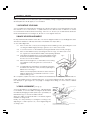
Loosen the tension on the blade by turning the blade tension knob (see fig.1).
2.3
Remove the table insert, by squeezing the the two lugs, one either side of the
slot, together, from beneath the table, whilst pushing upwards.
2.4
Disengage the blade pins from the upper blade holder,
then the lower blade holder and pull the blade through
the access hole in the table.
2.5
Slacken off the single hex. socket head screw securing
lower blade holder, using the hex socket wrench
supplied.
2.6
A metal strip is provided which should be inserted into
the blade slots in both holders, thereby replacing the
blade as shown in fig. 2.
Fig. 2
With the steel strip in place and the holders therefore
aligned, tighten the lower blade holder hex. socket
head securing screw.
On completion, replace the side cover, table insert and blade by reversing the procedure above.
NOTE: If the blade tends to wander during use, re-check this adjustment as it may take one or
two attempts to get it right. Also see page 8 - Straight Line Cutting, for other causes of blade
wander.
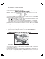
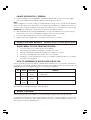
Fig. 3
3. TABLE ALIGNMENT (see fig. 3)
To ensure the table is correctly aligned, i.e. is at right angles
to the blade, loosen the table securing knob, and level
the table by bringing a small square up to the blade, as
illustrated in fig.3. to ensure the table is at 90o.
When the table is perpendicular to the blade, tighten
thetable securing knob.
Finally, zero the pointer by loosening the securing screw,
adjusting it so that it points to 0O, then retightening the
securing screw.
6