1
Notification
Notification is hereby given that TransTel Communications, Inc. reserves the right to modify, change, update or
revise this document from time to time as required without the prior obligation to notify any person, company or
organization. Further, TransTel Communications, Inc. makes no warranty or representation, either express or
implied, with respect to merchantability, or fitness of its products for a particular purpose.
© 2003 TransTel Communications, Inc.
This document or any parts thereof are not to be reproduced or transmitted in any form or by any means,
electronic or mechanical, including photocopying, recording, or information storage and retrieval systems for any
purpose whatsoever without the express written permission of TransTel Communications, Inc.
Last Update January 21, 2003
IMPORTANT SAFETY INSTRUCTIONS
Installation Safety Precautions:
1. Never install telephone wiring during a lightning storm.
2. Never install telephone jacks in wet locations unless the jack is specifically designed
for wet locations.
3. Never touch un-insulated telephone wires or terminals unless the telephone line has
been disconnected at the network interface.
4. Use caution when installing or modifying telephone lines.
The TransTel TD-1648i/TDS-600 utilizes a 3 pin grounding power supply cord. This cord is not to be attached to any
building surfaces. When using your telephone equipment, basic safety precautions should always be followed to reduce the
risk of fire, electric shock and injury to persons, including the following:
1. Read and understand all instructions.
2. Follow all warnings and instruction marked on the
product.
3. Unplug this product from the wall outlet before
cleaning. Do not use liquid cleaners or aerosol
cleaners. Use a damp cloth for cleaning.
4. Do not use this product near water, for example, near
a bath tub, wash bowl, kitchen sink, or laundry tub, in
a wet basement, or near a swimming pool.
5. Do not place this product on an unstable cart, stand,
or table. The product may fall, causing serious
damage to the product.
6. Slots and openings in the cabinet and the back or
bottom are provided for ventilation, to protect it from
overheating, these openings must not be blocked or
covered. The openings should never be blocked by
placing the product on the bed, sofa, rug, or other
similar surface. This product should never be placed
near or over a radiator or heat register. This product
should not be placed in a built-in installation unless
proper ventilation is provided.
7. This product should be operated only from the type of
power source indicated on the marking label. If you
are not sure of the type of power supply to your home
or office, consult your dealer or local power company.
8. The socket-outlet shall be installed near the equipment
and shall be easily accessible.
9. This product is equipped with a three wire grounding
type plug, this plug will only fit into a grounding type
power outlet. This is a safety feature. If you are
unable to insert the plug into the outlet, contact your
electrician to replace your obsolete outlet. Do not
defeat the safety purpose of the grounding type plug.
10. Do not allow anything to rest on the power cord. Do
not locate this product where the cord will be
damaged by persons walking on it.
11. Do not overload wall outlets and extension cords as
this can result in the risk of fire or electric shock.
12. Never push objects of any kind into this product
through cabinet slots as they may touch dangerous
voltage points or short out parts that could result in
a risk of fire or electric shock. Never spill liquid of
any kind on the product.
13. To reduce the risk of electric shock, do not
disassemble this product, but take it to a qualified
service man when some service or repair work is
required. Opening or removing covers may expose
you to dangerous voltages or other risks. Incorrect
reassemble can cause electric shock when the
appliance is subsequently used.
14. Unplug this product from the wall outlet and refer
servicing to qualified service personnel under the
following conditions:
A. When the power supply cord or plug is damaged or
frayed.
B. If liquid has been spilled into the product.
C. If the product has been exposed to rain or water.
D. If the product does not operate normally by
following the operating instructions. Adjust only
those control, that are covered by the operating
instructions because improper adjustment of other
controls may result in damage and will often require
extensive work by a qualified technician to restore
the product to normal operation.
E. If the product has been dropped or the cabinet has
been damaged.
F. If the product exhibits a distinct change in
performance.
15. Avoid using a telephone (other than a cordless type)
during an electrical storm. There may be a remote
risk of electric shock from lightning.
16. Do not use the telephone to report a gas leak in the
vicinity of the leak.
SAVE THESE INSTRUCTIONS
Digital Telephone System
General Description - Installation - Programming Manual
GENERAL DESCRIPTION – INTRODUCTION .................................................................................................10
FCC RULES AND REGULATION......................................................................................................................10
Ringer Equivalence Number ...........................................................................................................................10
Notification of the Telephone Company ..........................................................................................................10
Direct Connection to a Party-Line or Coin Operated Telephone Line is Prohibited. .........................................10
Incidence of Harm to the Telephone Lines......................................................................................................10
Compatibility of the Telephone Network and Terminal Equipment. .................................................................11
Radio Frequency Interference.........................................................................................................................11
CTR 21 (98/482/EC) DECLARATION NETWORK COMPATIBILITY.................................................................11
ISDN INSTALLATION .......................................................................................................................................11
KEY HIGHLIGHTS OF THE TD-1648I/TDS-600 SERIES INCLUDE: ................................................................13
Economy and Efficiency .................................................................................................................................13
Easy Installation .............................................................................................................................................13
Easy Maintenance ..........................................................................................................................................13
Flexibility of System Applications....................................................................................................................13
Varied Extension Alternatives .........................................................................................................................13
Digital Twin Port .............................................................................................................................................13
Hybrid Phone ..............................................................................................................................................14
Full ISDN features.......................................................................................................................................14
Liquid Crystal Display..................................................................................................................................14
Mechanical Specifications (Key Service Unit) .................................................................................................16
Mechanical Specifications (Battery Back Up Housing) ....................................................................................16
Environmental Specifications..........................................................................................................................16
FEATURES........................................................................................................................................................17
System Features.............................................................................................................................................17
DISA ..................................................................................................................................................................17
SYSTEM PROGRAMMING................................................................................................................................17
ADVISORY MESSAGES ................................................................................................................................... 19
Optional Features........................................................................................................................................... 19
PARTS & PERIPHERALS................................................................................................................................. 20
System Modules............................................................................................................................................. 20
Type of Phones.............................................................................................................................................. 20
Peripheral Devices......................................................................................................................................... 20
Optional Interface Cards ................................................................................................................................ 20
SYSTEM INSTALLATION - INTRODUCTION .................................................................................................. 21
SITE REQUIREMENTS..................................................................................................................................... 22
Location ......................................................................................................................................................... 22
Choosing the Right Environment................................................................................................................. 22
Installation Checklist ...................................................................................................................................... 22
EQUIPMENT REQUIREMENTS........................................................................................................................ 22
INSTALLATION ................................................................................................................................................ 23
Installing the Equipment ................................................................................................................................. 23
Backboard .................................................................................................................................................. 23
Key Service Unit ......................................................................................................................................... 23
Power Supply.............................................................................................................................................. 23
Installing expansion and optional cards .......................................................................................................... 23
Card Introduction............................................................................................................................................ 24
Installing CPU and option cards .................................................................................................................. 25
G2-IPU ....................................................................................................................................................... 25
G2-MSU- Multi Service Card ...................................................................................................................... 25
G2-STU Digital Station Card....................................................................................................................... 27
G2-SLU Analog Station Card ...................................................................................................................... 28
G2-TKU- 4 Port CO Line Card ................................................................................................................... 28
G2-CIC- Caller ID Card............................................................................................................................... 29
G2-SIU ISDN S/T Interface Card ................................................................................................................ 29
Voltage Selection Check............................................................................................................................. 31
Replace Fuses of Power Supply ................................................................................................................. 32
Replace Cover............................................................................................................................................ 32
Preparing the External Battery Backup ....................................................................................................... 32
Charging the Battery ................................................................................................................................... 33
Installing or Replacing Batteries.................................................................................................................. 33
System Ground........................................................................................................................................... 34
Connecting Stations.................................................................................................................................... 34
Digital Key Telephone – DK1 Series, DK2 Phones and DSS Console ......................................................... 35
Digital Key Telephone – DK-1D or DK-1S with SLC1 Circuit Pack installed................................................. 36
Access Control Telephone – ACP ............................................................................................................... 37
Single Line Telephone (connected to G2-SLU) ........................................................................................... 38
Door Phone Connection.............................................................................................................................. 38
Single Line Telephone (connected to ATA) ................................................................................................. 39
CO/PABX Connections ............................................................................................................................... 39
ISDN S/T Connections................................................................................................................................ 39
Optional Cabling ............................................................................................................................................ 42
Door Switch (Relay) Connection ................................................................................................................. 42
Sensor Connection ..................................................................................................................................... 42
Paging Connection...................................................................................................................................... 42
Music on Hold Connection .......................................................................................................................... 43
RS232 Port Connection .............................................................................................................................. 43
Power On and Operational Test ..................................................................................................................... 44
Operational Tests ....................................................................................................................................... 44
Special Immunity Protection for System and terminals................................................................................... 44
For Power Supply:.......................................................................................................................................44
For Line:......................................................................................................................................................44
SERIES MODEL TD-1648I/TDS-600 - PROGRAMMING MANUAL ...................................................................45
Programming Information ...............................................................................................................................45
New Systems ..............................................................................................................................................45
To Reset System Memory. ..........................................................................................................................45
To Enter System Programming: ..................................................................................................................45
Basic Programming Commands ..................................................................................................................46
Alphanumeric Entry.....................................................................................................................................47
Form 01 - Day Ringing and Ringing Line Preference Assignment ...................................................................48
Form 02 - Night Ringing and Ringing Line Preference Assignment .................................................................48
Form 03 - Door Phone Ringing Assignment Form ...........................................................................................49
Form 04 - Console (Operator) Assignment Form ...........................................................................................50
Form 05-01 - System Parameters Form - Timers-1.........................................................................................51
Form 05-02 - System Parameters Form - Timers-2.........................................................................................53
Form 05-03 - System Parameters Form - Codes-1..........................................................................................55
Form 05-04 - System Parameters Form - Codes-2..........................................................................................57
Form 05-05 - System Parameters Form - Codes-3..........................................................................................59
Form 05-06 - System Parameters Form - Timer/Codes...................................................................................61
Form 05-07 - System Parameters Form - Timer/Codes...................................................................................63
Form 05-08 - System Parameters Form - Timer/Codes...................................................................................66
Form 05-09 - System Parameters Form - Misc. ..............................................................................................68
Form 05-10 - Voice Mail Leading Digits ..........................................................................................................70
Enhanced Protocol ......................................................................................................................................71
Answering Machine Operation.....................................................................................................................71
Record Function..........................................................................................................................................71
Direct To Voice Mail ....................................................................................................................................71
Message Waiting Digits...............................................................................................................................72
More About Voice Mail ................................................................................................................................72
Form 05-11 - System Parameters Form - Supplemental. ................................................................................73
Form 05-12 - System Parameters Form - Miscellaneous.................................................................................75
Form 05-13 - System Parameters Form - Miscellaneous.................................................................................77
Form 05-14 - System Parameters Form - Miscellaneous.................................................................................79
Form 05-16 - System Parameters Form - Miscellaneous.................................................................................80
Form 06-01 - Relay Assignment Form ............................................................................................................81
Form 07-gp-IP - Flexible Key Group Assignment ...........................................................................................82
DK-2 Key Layout.............................................................................................................................................84
DK-3 Key Layout.............................................................................................................................................85
Form 08-gp-IP - DSS Key Group Assignment ................................................................................................86
Form 09-nnn-DP - System Speed Dial ...........................................................................................................87
Pre-Assigned CO Line: ...................................................................................................................................87
Telephone Number: ........................................................................................................................................87
Form 10-gp-IP - Intercom or DISA Single Digit Assignment ...........................................................................88
Form 11 - Date and Time Settings ..................................................................................................................89
Form 12 - System Alarm Schedule ................................................................................................................89
Form 13 - System Passwords .........................................................................................................................90
Form 14 - Station Message Detail Recording ..................................................................................................91
Form 17 - Forced Account Code Assignment..................................................................................................95
Form 18 - Toll Plan Assignment......................................................................................................................96
Form 20 - Day/Lunch/Night Service Switching Schedule.................................................................................98
Form 25 - Reset Data to System Default.........................................................................................................99
Form 29 - CO Line Specifications #1 ...........................................................................................................100
Form 35 - CO Line Specifications #2 ...........................................................................................................103
Form 36 - CO Line Groups (Dial 9 Groups)..................................................................................................105
Form 37 - Busy Out CO Trunk ......................................................................................................................106
Form 38 - Alternate CO Line Groups (Dial 87 Groups).................................................................................107
Form 39-000-IP - Sensor Assignments .........................................................................................................108
Form 40 - Station Class of Service (Part 1) ................................................................................................. 109
Form 41 - Station Specifications................................................................................................................... 111
Form 42 - Personal Speed Dial Table Assignment ....................................................................................... 112
Form 43 - Port Assignments......................................................................................................................... 113
Form 44 - Station Class of Service (Part 2) ................................................................................................. 115
Form 45 - Station Class of Service (Part 3) ................................................................................................. 117
Form 46 - Station Class of Service (Part 4) ................................................................................................. 119
Form 47-st-IP - Hot Line Assignment........................................................................................................... 122
Form 50 - Station Class of Service (Part 5) ................................................................................................. 123
Form (51 to 59)-code-IP - Toll Plans – Allowed Digits – Class 1 to 9 ........................................................... 124
Form (61 to 66)-code-IP - Toll Plans – Restricted Digits – Class 1 to 6........................................................ 125
Toll Control Examples............................................................................................................................... 126
Example 2 ................................................................................................................................................ 126
Form 67 - Hunt Group Pilot Number Assignment.......................................................................................... 127
Form 68 - Day Hunt Group Assignments ...................................................................................................... 128
Form 69- Night Hunt Group Assignments ..................................................................................................... 129
Form 70-Cd-IP - ISDN Interface Specifications Program ............................................................................ 130
Form 71-tk - Reserved for Future Used ....................................................................................................... 131
Form 72-St - ISDN Called Party Extension Number Assignment ................................................................. 131
Form 73-St - ISDN Extension Sub-Address Assignment ............................................................................. 132
Form 75-Num-IP - LCR - Analysis Table ..................................................................................................... 133
Form 76-Num-Tm - LCR – Routing Table.................................................................................................... 134
Form 77-Num - LCR – Modifying Table....................................................................................................... 135
Form 78-st-IP - Station Class of Service – 6................................................................................................ 136
Form 83-st-IP - Caller ID Block Assignment ................................................................................................ 138
Form 84-IP - Home Area Code.................................................................................................................... 139
Form 85-nn-IP - Overlay Area Code............................................................................................................ 139
Form 86-nnn-IP - Office Code Redial Pattern.............................................................................................. 140
PROGRAMMING CROSS REFERENCE......................................................................................................... 141
Incoming Calls ............................................................................................................................................. 141
Ringing Assignment .................................................................................................................................. 141
Outgoing Calls ............................................................................................................................................. 141
Dial ‘9'....................................................................................................................................................... 141
PABX Outgoing Code ............................................................................................................................... 141
Trunk Specifications ................................................................................................................................. 141
Speed Dial ................................................................................................................................................ 141
Auto-Redial............................................................................................................................................... 141
Intercom Calls.............................................................................................................................................. 141
Intercom Call Signaling............................................................................................................................. 141
Step Call................................................................................................................................................... 142
Dial Tone Pattern...................................................................................................................................... 142
Direct Station Select ................................................................................................................................. 142
Dial 0 (Call Operator)............................................................................................................................... 142
Intercom Dialing Restriction ...................................................................................................................... 142
Busy/During Conversation............................................................................................................................ 142
Hold and Hold Recall ................................................................................................................................ 142
Busy Remind / Camp-On .......................................................................................................................... 142
Call Split ................................................................................................................................................... 142
Transfer .................................................................................................................................................... 142
Message Waiting Level............................................................................................................................. 142
Override ................................................................................................................................................... 142
DISA ............................................................................................................................................................ 142
DISA Single Digit Dialing .......................................................................................................................... 143
Automated Attendant - Voice Service Unit ............................................................................................... 143
Night Service ............................................................................................................................................... 143
Group Assignments...................................................................................................................................... 143
Console Assignment ................................................................................................................................. 143
Flexible Key Group Assignments .............................................................................................................. 143
Dial ‘9' Trunk Groups.................................................................................................................................143
Dial ‘87' Trunk Groups...............................................................................................................................143
Group Assignment for stations (Page Zone, Pick up, Single digit) .............................................................143
Call Control...................................................................................................................................................143
Toll Restriction ..........................................................................................................................................143
Forced Account Codes ..............................................................................................................................143
Call Limit...................................................................................................................................................143
Passwords.................................................................................................................................................144
Station Lock/Unlock...................................................................................................................................144
Busy out a trunk ........................................................................................................................................144
Intercom Dialing restrictions ......................................................................................................................144
System Clock ...............................................................................................................................................144
Date and Time Setup ................................................................................................................................144
System Alarm............................................................................................................................................144
Wake Up calls...........................................................................................................................................144
Station Numbering........................................................................................................................................144
Single Line Telephone ..................................................................................................................................144
Miscellaneous...............................................................................................................................................144
Monitor......................................................................................................................................................144
Paging.......................................................................................................................................................144
Call Forward No Answer Transfer Time .....................................................................................................144
Hot Line ....................................................................................................................................................145
Optional Services .........................................................................................................................................145
Door phone & Door switch .........................................................................................................................145
Voice Mail Integration................................................................................................................................145
By Program Type in Alphabetical Order........................................................................................................146
System Parameters...................................................................................................................................146
Class Of Service/Station programming......................................................................................................148
TRANSTEL KEY TELEPHONE OPERATION MANUAL. ................................................................................150
Introduction ...............................................................................................................................................150
1A2 Emulation / Privacy Release ..............................................................................................................150
Account Codes – Client .............................................................................................................................150
Advisory Messages ...................................................................................................................................150
Alternate Trunk Group Access (Dial 87).....................................................................................................151
Answering Calls.........................................................................................................................................151
Answering a Doorphone ............................................................................................................................152
Answer Paging (Meet Me Page) ................................................................................................................152
Automatic Callback ...................................................................................................................................152
Automatic Last Number Redial ..................................................................................................................153
Automatic Line Access ..............................................................................................................................153
Automatic Redial .......................................................................................................................................153
Automatic Saved Number Redial ..............................................................................................................153
Background Music.....................................................................................................................................154
Barge-In (Override) ...................................................................................................................................154
Caller ID Features .....................................................................................................................................154
Call Forwarding .........................................................................................................................................155
To forward busy calls:................................................................................................................................155
To forward calls when you don’t answer or are busy: .................................................................................156
Call Hold ...................................................................................................................................................156
Calling the Doorphone...............................................................................................................................156
Call Pickup................................................................................................................................................156
Direct (Extension) Call Pickup ...................................................................................................................156
All Group Pickup .......................................................................................................................................156
Pickup within your group ...........................................................................................................................156
Pickup a caller in another group ................................................................................................................156
Call Swap..................................................................................................................................................157
Call Transfer .............................................................................................................................................157
Call Waiting (Camp On)............................................................................................................................ 157
Conference ............................................................................................................................................... 158
Conversation monitor................................................................................................................................ 158
Date and Time Setting (Operator Function)............................................................................................... 158
Day / Night Service Switching Setup (Operator function) .......................................................................... 158
Selecting Day or Night Mode When in Manual Switching Mode ................................................................ 159
Dialing Operator ....................................................................................................................................... 159
Direct Trunk Access.................................................................................................................................. 160
Do Not Disturb .......................................................................................................................................... 160
Environment Monitor ................................................................................................................................ 160
Exclusive Hold.......................................................................................................................................... 160
Feature Menu ........................................................................................................................................... 160
Flash (To an outside telephone line) ......................................................................................................... 161
Forced Account Codes.............................................................................................................................. 161
Handsfree Operation................................................................................................................................. 161
Immediate CO Line Access....................................................................................................................... 162
Intercom dialing ........................................................................................................................................ 162
Last Number Redial .................................................................................................................................. 162
Lock / Unlock SMDR from Console........................................................................................................... 163
Macro Keys............................................................................................................................................... 163
Mute ......................................................................................................................................................... 163
Operator Set Timed Reminder or Wakeup (Remote Setup) ...................................................................... 163
Operator Timed Reminder or Wake Up..................................................................................................... 164
Paging ...................................................................................................................................................... 164
Pulse To Tone Conversion........................................................................................................................ 164
Room Monitor ........................................................................................................................................... 164
Saved Number Redial............................................................................................................................... 165
Saved Number Redial (SuperSave) .......................................................................................................... 165
Shift Key................................................................................................................................................... 165
Speed Dialing ........................................................................................................................................... 165
Speed Dial Programming.......................................................................................................................... 166
Speed Dial Programming (Operator)......................................................................................................... 166
Station Lock / Unlock ................................................................................................................................ 167
Switching between Handsfree and Handset mode..................................................................................... 167
Timed Reminder or Wake Up ................................................................................................................... 168
Trunk Queuing.......................................................................................................................................... 168
Trunk Group Access (Dial 9) ..................................................................................................................... 168
Voice Service Unit (Operator Function)..................................................................................................... 168
To Record (Operator only): ....................................................................................................................... 168
To Playback (Operator only): .................................................................................................................... 169
Voice Mail Access..................................................................................................................................... 169
Voice Mail Live Call Recording ................................................................................................................. 169
Voice Mail Message Retrieval................................................................................................................... 170
Voice Mail Transfer Key............................................................................................................................ 170
Volume Control......................................................................................................................................... 170
Volume Levels Programming (Permanent) ............................................................................................... 170
Intercom (as doorphone)........................................................................................................................... 171
Outgoing call (as wall mount phone) ......................................................................................................... 171
Access via password................................................................................................................................. 171
Access via proximity card(Touch-N-Go).................................................................................................... 171
Access via password and proximity card................................................................................................... 171
Check out (lock) ACP (as wall mount phone) ............................................................................................ 171
Burglary Report......................................................................................................................................... 172
Time Display............................................................................................................................................. 172
As a wall mount phone.............................................................................................................................. 172
ACP Related Programming .......................................................................................................................... 172
Extension Number length for ACP ............................................................................................................ 172
’Voice’ announce or ‘ring’ announce for ACP............................................................................................. 172
Hunt group for ACP ................................................................................................................................. 172
Hunt Group Pilot Number ..........................................................................................................................172
Hunt Group Members................................................................................................................................172
Station Hunt Group Ringing Method ..........................................................................................................172
Station Function Form 46-st-08 .................................................................................................................173
Dial 9 Access (System Option) ..................................................................................................................173
Forced Account Code for ACP (as wall mount phone) ...............................................................................173
Password for ACP (as doorphone).............................................................................................................173
General Description – Introduction
The General Description section contains an easy to understand overview of the TransTel® TD-1648i/TDS-600
ISDN Digital Telephone System. It is the intent of this document to provide both technical and non technical
readers with information pertaining to the system building blocks, capabilities, key highlights, electrical, physical
and environmental characteristics of the TransTel TD-1648i/TDS-600 ISDN Digital Telephone System.
FCC Rules and Regulation
In compliance with the requirements of Part 68 of the Federal Communications Commission Rules and
Regulations for connection of terminal system equipment to the telephone network and for your convenience, the
following information is presented.
FCC Registration Number
The TransTel TD-1648i/TDS-600 is registered with the FCC in a dual registration capacity enabling the system
to operate as a key system only or as a hybrid system. The FCC Registration Numbers are 3A7KF03BGDS600
for key systems registration and 3A7MF03BGDS600 for hybrid operation.
Ringer Equivalence Number
Ringer Equivalence 0.3B.
Notification of the Telephone Company
Customers connecting terminal equipment to the telephone network shall, upon request of the
Telephone Company, inform the Telephone Company of the particular line(s) to which such
connection is made, the FCC registration number and ringer equivalence number (REN) of
the registered terminal equipment.
The REN is useful to determine the quantity of devices you may connect to your telephone
line and still have all of those devices ring when your telephone number is called. In most,
but not all areas, the sum of the REN's of all devices connected to one line should not exceed
five (5.0). To be certain of the number of devices you may connect to your line, as
determined by the REN, you should contact your local telephone company to determine the
maximum REN for your calling area.
This equipment is capable of providing users access to Interstate providers of operator
services through the use of access codes. Modification of this equipment by call aggregators
to block access dialing codes is a violation of the Telephone Operator Consumers Act of
1990.
Direct Connection to a Party-Line or Coin Operated Telephone Line is Prohibited.
Incidence of Harm to the Telephone Lines
Should terminal equipment cause harm to the Telephone Network, the Telephone Company shall, where
practical, notify the customer that service may be temporarily discontinued. However, where prior notice is not
practical, the Telephone Company may temporarily discontinue service, if such action is reasonable in the
circumstances. In case of such un-notified temporary discontinuance of service, the Telephone Company
shall:
(a)
Promptly notify the customer of such temporary discontinuance of service.
(b)
Afford the customer the opportunity to correct the situation which gave rise to the temporary
discontinuance.
(c)
Inform the customer of the right to bring a complaint to the FCC pursuant to the procedures
set out in Subpart E of Part 68 of FCC Telephone Equipment Rules.
10
Issue 1.0 March, 2006
TransTel TD-1648i / TDS-600 - General Description
Compatibility of the Telephone Network and Terminal Equipment.
(a)
Availability of telephone interface information.
Technical information concerning interface parameters and specifications not specified in
FCC Rules, including the number of Ringers which may be connected to a particular line,
which is needed to permit Terminal Equipment to operate in a manner compatible with
Telephone Company communications facilities, shall be provided by the Telephone Company
upon customer's request.
(b)
Changes in Telephone Company Communications Facilities, Equipment, Operations and
Procedures.
The Telephone Company may make changes in its communications facilities, equipment, operations or
procedures where such action is reasonably required in the operation of its business and is not inconsistent
with the rules and regulations in FCC Part 68 of the FCC Rules and Regulations. If such changes can be
reasonably expected to render any customer Terminal Equipment incompatible with Telephone Company
Communications Facilities, or require modification or alteration of such Terminal Equipment, or otherwise
materially affect its use or performance, the customer shall be given adequate notice in writing to allow the
customer an opportunity to maintain uninterrupted service.
Radio Frequency Interference
This equipment generates and uses radio frequency energy and if not installed and used properly and in strict
accordance with the manufacturer's instructions, may cause interference to radio and television reception. It
has been type-tested and found to comply with the limits for a Class A computing device in accordance with the
specification in Subpart J of Part 15 of FCC Rules, which are designed to provide reasonable protection against
such interference in a residential installation. However, this is no guarantee that interference will not occur in a
particular installation. If this equipment does cause interference to radio or television reception, which can be
determined by turning the equipment off and on, the user is encouraged to try to correct the interference by one
or more of the following measures:
Re-orient the receiving antenna.
Relocate the equipment with respect to the receiver.
Move the equipment away from the receiver.
Plug the equipment into a different outlet so that equipment and receiver are on different branch
circuits.
CTR 21 (98/482/EC) Declaration Network Compatibility
CTR 21 (98/482/EC) Declaration Network Compatibility, The equipment has been approved in accordance with
Council Decision 98/482/EC for pan-European single terminal connection to the public switched telephone
network (PSTN). However, due to differences between the individual PSTNs provided in different countries, the
approval does not, of itself, give an unconditional assurance of successful operation on every PSTN network
termination point. In the event of problem, you should contact your equipment supplier in the first instance.’
ISDN Installation
For the ISDN unit (G2-SIU), TD-1648i/TDS-600 only offers ISDN S/T interface connection behind NT1 device. It
could not be connected to “U” interface directly.
11
Description
The TD-1648i/TDS-600 is an advanced ISDN Digital hybrid telephone system employing a microprocessor
stored program and digitally controlled solid state Time-division switching. The TD-1648i/TDS-600 system is
specifically designed for small business as well as residential applications. At the forefront of the system design
is a universal concept to adapting and connecting with a variety of communications devices. Productive
TransTel Digital Key Telephones offer thoughtfully designed productive feature access to keep you connected
with one another and customers. TransTel technology leads the industry in providing for compatibility with
devices such as fax machines, answering machines, cordless phones, computer modems and other office/home
12
Issue 1.0 March, 2006
TransTel TD-1648i / TDS-600 - General Description
equipment.
Key highlights of the TD-1648i/TDS-600 series include:
Economy and Efficiency
The base system is equipped to support four (4) CO lines / two (2) or three (3) ISDN BRIs and eight (8) digital
stations. The system may be expanded to a maximum of sixteen (16) CO lines / six (6) ISDN BRIs or Twentyfour 24 ISDN PRI Channels. Station cards may be selected to allow practically any combination ranging from all
TransTel DK1 Digital Sets to all industry standard Single Line Telephone sets, with any combination of the two
types. In addition to being cost effective at the initial phase and for expanding to it's maximum capacity. This
allows a wide variety of applications for the system to work effectively.
Easy Installation
•
•
“Factory Ready” - All TD-1648i/TDS-600 Telephone systems are "ready to go" right out of the box. A well
thought out default database is factory installed on each system which meets the needs for most
installations. This alleviates hours of on site time, minimizing installation costs for both dealer and customer.
“Small & Compact” - The Key Service Unit's small size takes little space for installation and is about the size
of a legal piece of paper.
Easy Maintenance
•
Solid-state design minimizes trouble and eliminates periodic maintenance.
•
Easy Expansion. Various Interface Cards for simple, modular expansion.
•
Versatile programming and options for ease of selection.
•
Database Flash Memory Back Up - Customer data is backed up when the power is turned off and there is no
battery to replace.
•
Battery Back Up (System Operation) - TD-1648i/TDS-600 systems can be equipped with an optional battery
back up which keeps the system operational for up to 1 hour in the case of a commercial power failure.
•
Customer Care Programming - Customers and service personnel can easily communicate and perform
programming right over the telephone. TransTel telephone systems allow programming and voice
conversations to be performed at the same time.
•
Advanced software upgrades – Through the RS232 connection, system software can be upgraded easily
without a chip change.
Flexibility of System Applications
Unlike other conventional systems in the TD-1648i/TDS-600 size range, the installer will find an unprecedented
range of customer database programmability. In "system parameters" there are extensive options for various
timing settings related to features. An array of parameters are programmable for signaling options on outside
lines and internal single line telephone sets. The installer may Enable/Disable many system wide features. And
in class of service, there are over 20 options for each station providing maximum flexibility for nearly any
application.
Varied Extension Alternatives
You can connect an ISDN Modem, ISDN phone, proprietary TransTel DK series Keyphone, Access Control
Phone (ACP), Door Phone and conventional industry standard single line sets – Modem, Answering Machine,
Cordless phone, etc. directly to the KSU. This feature provides you with the choice to select different extension
equipment to suit individual applications.
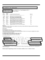
Digital Twin Port
Install two Digital Keyphones on a single two-wire cable. No Master and Slave difference. Any keyphone can be
plugged in and plugged out with no interference to the other. This feature provides easy cabling, easy expansion
and easy maintenance.
13
Hybrid Phone
Use your current telephone equipment, such as Modems, cordless telephones, Answering machines, etc. Just
plug this equipment into the Analog port of the key telephone and the call can be automatically transferred to the
equipment when you are busy or do not answer. No extra wiring and programming. This feature provides easy
installation and programming-free transfer of calls from the key telephone to Analog Single Line equipment.
Full ISDN features
The TDS 600 system allows you to access different outside line types (PSTN & ISDN BRI, PRI, T1, E1, …) in
one box and enjoy Full ISDN Features when accessing an ISDN Line - such as:
. Call Charge Metering Information
. Caller Identification
. Direct Inward Dialing
. Call Forward Internal / External
. Call Waiting
. MSN (Multiple Subscriber Number)
. Sub-addressing
. User to User Signaling
You can easily control your budget by using different outside line arrangements.
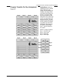
Liquid Crystal Display
The DK1 Series Telephone Model DK-1D is equipped with a large, easy to read LCD display. The LCD is 32
characters total, comprised of 2 rows by 16 characters each.
The DK2 Series Telephone Model DK2-21 is equipped with a large, easy to read LCD display. The LCD is 64
characters total, comprised of 4 rows by 16 characters each
This LCD provides an invaluable tool for simplifying the use of the telephone by identifying the calling extension
by name, outside lines by name and self prompting displays for feature access. Station feature usage is made
simple with the help of the LCD display. Continuous prompting information is displayed during calls so that users
know what to do and when to do it.
32-character LCD Display shows:
• Time
• Dialed telephone number
• Voice Mail Messages
• CO Line Names
• Last Number Redial
• Speed dial number
14
•
•
•
•
•
•
Last number dialed
The status of operation/function
Absent messages
Speed Dial Directory
Calling Party Number and Name
Input data during system data entry
Issue 1.0 March, 2006
TransTel TD-1648i / TDS-600 - General Description
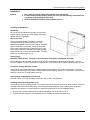
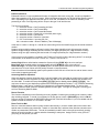
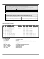
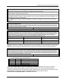
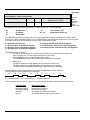
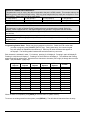
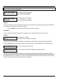
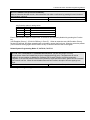
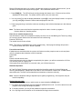
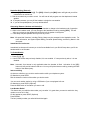
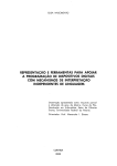
TransTel Telephone Model DK-1D / DK1-S
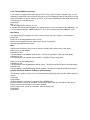
DK-ACP Access Control Phone
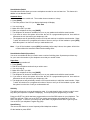
TransTel Telephone Model DK-2
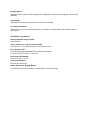
DK-ATA Analog Terminal Adapter
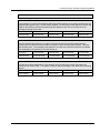
15
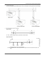
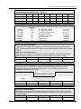
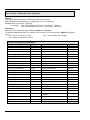
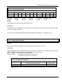
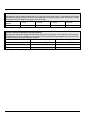
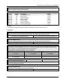
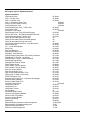
MAXIMUM LOOP RESISTANCE/IMPEDANCE
Key Telephone
Less than 40 ohms 26 AWG / 200 m
Single Line telephone
Less than 800 ohms 26 AWG / 800 m
Doorphone
Less than 40 ohms
Music Source Input Impedance
600 ohms
Maximum Input
0.775 VRMS
INTERNAL RELAY CONTACTS
Type
SPST
Rating
1 AMP, 24VDC
Function
Door Switch, Music on Hold, etc
CABLE REQUIREMENTS
CO/PABX Line
Twisted 1 Pair (2 wires)
ISDN BRI
Twisted 2 Pair (4 wires)
ISDN PRI
DK1/DK2/ACP Digital Key Telephone Twisted 1 Pair (2 wires)
Doorphone
Twisted 1 Pair (2 wires)
Door Switch
Twisted 1 Pair (2 wires)
External Sensor
Twisted 1 Pair (2 wires)
External Music Source
Twisted 1 Pair (2 wires)
Single Line Telephone
Twisted 1 Pair (2 wires)
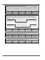
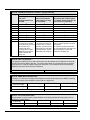
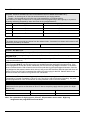
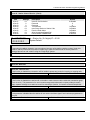
Mechanical Specifications (Key Service Unit)
CABINET DIMENSIONS
357mm W
14.1”
WEIGHT
126mm D
4.96"
17 Kg (Configuration: 4 x 8)
37.4 lbs
436mm H
17.2”
Mechanical Specifications (Battery Back Up Housing)
CABINET DIMENSIONS
15.5” W
WEIGHT
Mounting Screws
3.0” D
5.75” H
With Batteries -16 lbs Without Batteries- 4 lbs.
12.25” center to center
Environmental Specifications
OPERATING CONDITIONS
Temperature
Humidity
16
0º to 45º C
(32º to 113º F)
10 to 95% relative
Non-condensing
STORAGE
CONDITIONS
-40º to 66º C
(-40º to 150º F)
10 to 95% relative
non-condensing
Issue 1.0 March, 2006
TransTel TD-1648i / TDS-600 - General Description
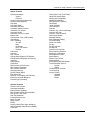
Features
System Features
Account Code Capability
Attendant Console Assignment
Attendant Overflow
Automatic Line Access
Automatic Line Search
Automatic Ringdown
Automatic Wake-up
Battery Charger
Behind PABX Operation
Centrex Operation
Class Of Service
CO Line Groups
CO Line Hunting
CO Line Name Programming
CO Line Ring Types
Linear
Common Audible
Circular
Hunt
Console Assignment
Day/Night Service
Manual/Automatic Switch
Dial 9 Group
Direct In Line
Dial By Name
Dial Mode Selection(DP/DTMF)
Dial Pulse to DTMF Conversion
Distinctive Ringing
DTMF Signaling
Dual Port Capability
End to End Signaling
Easy Installation and Operation
Flash (Programmable)
Flash Memory Backup Memory
Flexible Expansion
Flexible Ringing Assignment
Flexible Key Group Assignment
Flexible Number Plan 2,3 or 4 Digit
Flexible Time Format 12/24 Hour
Forced Account Code Assignment
Intercom
Intercom Single Digit Assignment
Intercom Ring / Voice Select
Intercom Dialing Restriction
ISDN
Call Charge Metering Information
Caller Identification
Direct Inward Dialing
Call Forward Internal / External
Call Waiting
MSN (Multiple Subscriber Number)
Sub-addressing
User to User Signaling
Host PABX Access
Hot line
Line Group Assignment
Loud Bell Assignment
Multiple Attendant Consoles
Multiple Trunk Groups
Night Transfer
On Call Programming
Paging
Internal
Zone
Meet Me
Password Assignment
DISA
System programming
Toll Override
Pause
Pick Up Groups
Power Fail Transfer
Security Code
Single Digit Dialing
Station Group Assignment
Station Hunting
Station Lock
System Speed Dial and Personal Speed Dial
System Date & Time Setting
System Time-Reminder Service
Telephone Directory
Toll Control
Day / Night
Tone to pulse dialing
Trunk Queuing
Trunk to trunk connections
Uniform Call Distribution
Voice Mail Compatibility
17
TransTel TD-1648i / TDS-600 - General Description
Station Features
Advisory Messages
System
Personal
Access to System Programming
Account Code Capability
Auto Hold
Auto Hold Recall
Automatic Call Back
Automatic Answer-Intercom
Automatic Line Access
Automatic Redial
Automatic Volume Increase
Brokers Call
Call Duration Timer (LCD Phones)
Call Waiting
Call Forwarding
All Calls
Busy
No Answer
Busy / No Answer
External
Call Pickup
Call Split
Call Transfer
Calling Name Display (LCD Phones)
Calling Number Display (LCD Phones)
Camp On
Chain Dialing
Conference
Dial By Name (LCD Phones)
Dial Access to Attendant
Direct Station Selection
Doorphone Access
Do Not Disturb (DND)
Dual Color LED
Duration Time Display (LCD Phones)
Executive Override (Barge-In)
External Call Forwarding
Flash (Open Loop Timed Flash)
Hands-free Answer Back
Hearing Aid Compatibility
Headset Compatibility
Hold (Exclusive / System)
Hold Recall
I Hold Indication
I Use Indication
Intercom
Intercom ring / voice interchange
Intercom Step Call
Intercom Voice Announce
Last Number Redial
Message Waiting
Multi-Language Display
On Hook Dialing
Prime Line Select
Privacy
Privacy Release
Private Line
Pulse/Tone Conversion
Ring Frequency Selection
Ringing Line Preference
Saved Number Redial
Speed Dialing
Station Lock / Unlock
Station Monitor
Store Speed Dial/DSS Number
Timed Reminder Service
System
Station
Toll Restriction Override
Trunk Queuing
Volume Control
Handset
Speaker
Ringer
Optional Features
Access Control Phone
Automated Attendant
Battery Backup (System)
Direct Inward System Access (DISA)
Door phone / Door Latch
Dual Port Operation
External Music Source
Music On Hold
Relay Control
RS232
Security Sensor/Door Open Indication
Station Message Detail Record (SMDR)
Voice Mail
19
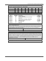
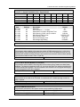
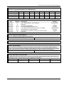
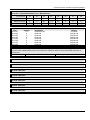
Parts & Peripherals
System Modules
Model
G2-MMD
G2-MPU
G2-IPU
G2-MSU
G2-TKU
G2-PIU
G2-SIU-2
G2-SIU-3
G2-STU
G2-SLU
G2-PWU
Description
KSU with Power Modular
G2 128/144/300/600 Main CPU Controller
G2-1648 Main CPU Controller / G2 128/144/300/600 Interface Control Card.
Multi-Service Card (External Paging/ Relay/ Sensor / RS232/ MODEM
Interface/ Door Phone / External MOH Interface)
Trunk Card : 4 CO lines
ISDN PRI Interface: 24 Channels Maximum
ISDN S/T interface with 2 circuits
ISDN S/T interface with 3 circuits
Station Card : 4 Digital Twin-ports
Single Line Card : 8 SLT ports
G2 Power Supply
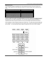
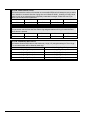
Type of Phones
Model
DK1-D/I
DK1-D/G
DK1-S/I
DK1-S/G
DK1-B/I
DK1-B/G
DK1-SLC-1
DK-ACP
DK-ATA
DK-WMK/I
DK-WMK/G
Description
Multifunction Key Telephone. Includes 32 character LCD display,
speakerphone, handsfree, headset jack, 20 dual color keys and 14 function
keys for feature access, DSS, CO Lines and speed dial. (Ivory or Gray)
Multifunction Key Telephone. Includes speakerphone, handsfree, headset
jack, 20 dual color keys and 14 function keys for feature access, DSS, CO
Lines and speed dial. (Ivory or Gray)
Multifunction Key Telephone. Includes speakerphone, intercom handsfree,
headset jack, 8 dual color keys and 14 function keys for feature access,
DSS, CO Lines and speed dial. (Ivory or Gray)
DK1 Keyphone - SLT port for DK1-2x series. Installs inside of digital
telephone DK1-D and DK1-S to proviide one analog port.
DK1-ACP Access Control Phone – Doorphone or Speakerphone (Ivory
only)
DK1-ATA Analog Terminal Adapter. Converts a digital station port into two
analog (SLT) ports.
Wall Mount Kit for DK1 Series Telephones
(Ivory or Gray)
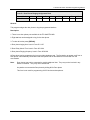
Peripheral Devices
Model
DPU05
BBOX0
BBOX1
Description
Door Phone - 2 Wires
Battery Box without Batteries
Battery Box with Batteries
Optional Interface Cards
Model
G2-VMU
G2-LMU
G2-CIC-F
G1-MDC
20
Description
Voice Mail Unit (4 Channels) / Auto Attendant / Wake-up / Message Waiting
LAN Management Unit
Caller ID Card for G2-TKU – FSK Mode
4 Channel Metering Card for G2-TKU
Issue 1.0 March, 2006
TransTel TD-1648i / TDS-600 Programming Manual
System Installation - Introduction
This section provides directions for installing the system and optional equipment.
The installation must be performed by qualified service personnel.
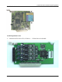
Main components of the system are:
Key Service Unit, which includes:
• Power Supply Unit (G2-PWU)
• Main KSU (G2-MMU)
• CPU Unit (G2-IPU)
• Multi-Service Unit (G2-MSU)
• Trunk Unit (G2-TKU / G2-SIU / G2-PIU)
• Digital Station Unit (G2-STU)
Optional Expansion Cards:
• Trunk Card (G2-TKU / G2-SIU / G2-PIU)
• Digital Station Card (G2-STU – four digital twin
port circuits)
• Single Line Station Card (G2-SLU – eight single
line port circuits)
• G2-CIC Card (Caller ID Card - four port circuits)
• Voice Mail Unit (G2-VMU)
• LAN Management Unit (G2-LMU)
• Metering Card (G1-MDC)
NOTE: Please follow the directions step by step. The TD-1648i/TDS-600 system should be installed in strict
accordance with this manual.
21
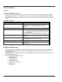
Site Requirements
Location
Choosing the Right Environment
•
System should be installed in a clean, dry, secure location. This location must have adequate ventilation,
and a temperature from 0
to 45 (32 to 113 ), with 10% to 95% non-condensing relative humidity.
DO NOT install the equipment near sources of static electricity, excessive vibration, or water. Avoid direct
sunlight.
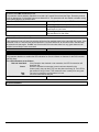
Installation Checklist
INSTALLATION REQUIREMENTS
VERIFICATION
MOUNTING SURFACE
Flat surface with adequate space for main cabinet,
power supply, wiring and optional Battery Backup
cabinet.
AC line should be dedicated exclusively to the system.
Power Outlet must be a
3-wire grounded outlet plug, having parallel blades
and ground pin.
Input power Line capacity requirements - 10 amperes.
A Surge Protector is recommended on the dedicated
AC line.
Humidity: 10% to 95% relative non-condensing
Temperature:32 to 113 (0
to 45 ).
AC LINE
POWER OUTLET
SURGE PROTECTION
VENTILATION AND TEMPERATURE
EARTH GROUND
SERVICEABILITY
A proper ground connection. (14 AWG)
Lighting conditions and working space adequate for
future service.
Equipment Requirements
•
•
•
22
Unpack, Check and Verify Equipment - Unpack the telephone equipment boxes and verify the contents in
accordance with the packing list provided. If any discrepancies are noticed, please contact TransTel or
Authorized Dealers.
Damaged Boxes - If you notice any damage to the packages, please notify both the shipper and TransTel or
Authorized Dealers at once.
List of parts included in basic KSU box:
• KSU Main Cabinet
• Power Supply
• Mounting Template
• Mounting Screws
• Station Quick Connectors
• Spare Fuses
• Cable Cover
Issue 1.0 March, 2006
TransTel TD-1648i / TDS-600 Programming Manual
Installation
Caution
1. This system should be installed by qualified service personnel.
2. Do not install the Power Supply unless you have read the following instructions and
completed all the installation and wiring.
3. STATIC SENSITIVE DEVICES! Please handle with care.
Installing the Equipment
Backboard
Be sure to plan and allow enough space to mount and
connect the key service unit, power supply and system
battery back up if applicable.
Key Service Unit
Use the enclosed Hanging Template to locate the
mounting position for the Key Service Unit. Drill
appropriately spaced holes to fix the Hanging Template
and mount the KSU on the wall. When mounting the
KSU, make certain that there is adequate room for the
future system expansion and that the connecting power
cable between the power mains and the KSU. The same
applies for the battery back up unit.
Power Supply
Dedicated Power Source - The power supply must be connected to a dedicated AC outlet.
Be sure that the third wire earth ground of the AC circuit is connected to a good electrical ground. If a music
source is installed, it must be connected to a separate AC circuit rather than the system's dedicated AC line cord.
Check Your Voltage Selection Jumper
Verify that the input voltage and input voltage jumper are correct before you power on the system. The input
voltage is set according to the Customer's requirement before shipping. However it is important to verify that the
setting is correct prior to initial system power up.
Power Supply voltage options for the unit:
100-VAC: 100 to 120 V AC (50/60Hz) or 240-VAC: 205 to 265 V AC (50/60Hz).
Installing expansion and optional cards
In this step you will be installing printed circuit cards on to slots of the main board in the basic cabinet. Take your
time and extra care to assure the printed circuit cards are properly aligned. After installing each option and
expansion card, perform a visual inspection to assure the printed circuit card is installed properly.
1. Remove the 4 screws located at the corners of the cabinet and lift the front cover off.
2. Install the specific cards into the dedicated slots of G2-MBU as below card introduction.
23
Card Introduction
1. CN1: Power socket to connect to the main
power unit (G2-PWU)
11. CN12: STU 1 slot
12. CN13: STU/SLU 2 slot
2. JP1: Reset jumper for flash memory
13. CN14: STU/SLU 3 slot
3. SW1: Cabinet position selection
14. CN15: STU/SLU 4 slot
4. CN2: LNU/MPU slot
15. CN16: STU/SLU 5 slot
5. CN3: VMU 1 slot
16. CN17: SLU slot 6
6. CN4: VMU 2 slot
17. CN18: TKU/SIU/PIU 1 slot
7. CN5: MSU slot
18. CN19: TKU/SIU 2 slot
8. CN6: IPU slot: G2-IPU slot
19. CN20: TKU/SIU 3 slot
9. CN8: DC power output
20. CN21: TKU/SIU 4 slot
10. CN9: Cabinet grounding for expansion
24
Issue 1.0 March, 2006
TransTel TD-1648i / TDS-600 Programming Manual
Installing CPU and option cards
G2-IPU
1. SW1: Reset button
2. JP1: Terminators for bus expansion of multi-cabinet.
3. JP2: Terminators for bus expansion of multi-cabinet.
4. Socket for the HDLC controller for bus expansion of multi-cabinet.
5. LED1: Heart beat LED
6. CN6: connector for expanding cabinet
7. CN5: connector for expanding cabinet
8. CN9: LCD connector
25
G2-MSU- Multi Service Card
1. JP1: Grounding Jumper for some specific external paging device
2. MODEM connector for the external MODEM connection to the system
3. RS232 connector
4. Relay / Sensor / External Paging connector
5. CN3: Door Phone Interface (for DPU05)
6. CN2: External Music on Hold Interface
26
Issue 1.0 March, 2006
TransTel TD-1648i / TDS-600 Programming Manual
G2-VSC- Voice Service Card
G2-STU Digital Station Card
Install this G2-STU card on STU1, STU/SLU2, …, STU/SLU5 slot of the G2-MBU.
27
G2-SLU Analog Station Card
Install this G2-SLU card on STU/SLU2, …, STU/SLU5, SLU6 slot of the G2-MBU.
G2-TKU- 4 Port CO Line Card
Install G2-CIC card or G1-MDC card on G2-TKU (optional).
Install this G2-TKU card on TKU1/TKU2/TKU3/TKU4 slot of the G2-MBU.
Connect an attached cable between CN4 of G2-TKU to CN3 of G2-SLU for power failure transfer.
CN6/CN7: G2-CIC-D/G1-CIC-F
CN2/CN3: G1-MDC 12/16
28
Issue 1.0 March, 2006
TransTel TD-1648i / TDS-600 Programming Manual
G2-CIC- Caller ID Card
Adjust JP1 of G2-CIC card for G2 use. And then install G2-CIC card on CN6/CN7 of G2-TKU card.
Misalignment could damage both cards or the system.
29
G2-SIU ISDN S/T Interface Card
Install this G2-SIU card on TKU1/SIU1 or TKU2/SIU2 slot of the G2-MBU.
JP3(A,B,C): DC feeding jumper. Default is no DC output. If the internal ISDN device does not offer local power
and need DC feeding to work. The related jumper of this internal ISDN interface needs to be set to “on”.
30
Issue 1.0 March, 2006
TransTel TD-1648i / TDS-600 Programming Manual
Caution:
1. When this jumper is on, users cannot loop “S” interface back to another “T” interface for testing purpose.
Otherwise, it will damage this card!
2. Incorrect jumper set will also damage this card.
JP1(A,B,C)/JP2(A,B,C): Bus Terminator.
Voltage Selection Check
Make a check to assure the power supply jumper setting is for the proper voltage.
When complete, place the power supply cover back on the power supply.
31
Replace Fuses of Power Supply
Replace Cover
Replace the cover and install the 4 screws removed earlier.
Preparing the External Battery Backup
The Key Service Unit can have two battery backup devices BBOX1 connected for emergency power when a
power failure takes place.
If you are installing an optional Battery Backup (BBOX1), make certain that there is adequate room for its
installation. Make certain that the Battery Backup is mounted close enough to the Power Supply that the
interconnecting cable between the Battery Backup and the Power Supply can connect.
Do Not Connect the Battery Backup at this time!
32
Issue 1.0 March, 2006
TransTel TD-1648i / TDS-600 Programming Manual
Do Not Connect the Battery Backup at this time! Battery Backup should not be
connected to the System power supply until all power up testing has been
completed!
Charging the Battery
The rechargeable batteries are automatically charged when the KSU is plugged in.
When System is in a full-load condition (eight CO Trunks and twenty-four Extensions all in use), the batteries
provide a minimum of 1 hour's consecutive use. Change the batteries every two years.
Installing or Replacing Batteries
Caution
To Reduce the Risk of Fire or Injury to persons, Read and Follow these Instructions.
1. Use only the following type and size batteries:
12 Volt 6.5 Amp/Hour "Gel-Cell" sealed batteries (2).
Dimensions, approximately 3 1/4" (H), 5 15/16" (W), 2 1/2" (D).
PowerSonic model PS660 or equivalent.
2. Do not dispose of the batteries in a fire. The cell may explode.
Check with local codes for possible special disposal instructions.
3. Do not open or mutilate the batteries. Released electrolyte is corrosive and may
cause damage to the eyes or skin. It may be toxic if swallowed.
4. Exercise care in handling batteries in order not to short the battery with conducting
materials such as rings, bracelets, and keys. The battery or conductor may overheat and cause burns.
This product is defined as a secondary battery operated device. As such, the following instructions
should also be read and followed:
1.
Charge the batteries provided with or identified for use with this product only in accordance with the
instructions and limitations specified in this manual.
2.
Observe proper polarity orientation between the batteries and battery charger.
3.
Do not mix old and new batteries in this product.
4.
Do not mix batteries of different sizes or from different manufacturers in this product.
Before installing or replacing batteries, disconnect the battery supply unit to the KSU by removing the polarized
battery connector at the KSU. Due to the weight of the batteries, it is advised that the battery cabinet be
removed from the wall before working on it.
33
System Ground
It is strongly recommended that the system be grounded by connecting a heavy, insulated copper wire (e.g.,
14AWG or larger) between the grounding bolt on the right-lower side of the cabinet and an earth ground. Without
this System Ground there is no protection against lightning damage to Co lines and warranty will be voided.
Do not connect the grounding wire of the KSU to a computer, telex, or any other external device.
Connecting Stations
The station cabling for the TD-1648i/TDS-600 should be a home run from the jack to the telephone room. The
termination should be at conventional 66 type connecting blocks or Krone or directly to the provided station
connectors. One pair twisted wiring is required for each station location. Attention to proper cabling will go a
long way towards a successful installation and minimizing service calls after installation. Some guidelines for
running station cable are as follows:
Avoid running cable parallel to fluorescent light fixtures or electrical lines not in conduit. If these obstacles
are unavoidable, run the cable at right angles across them.
Do not run station cable inside conduit already occupied by electrical wiring.
Do not run station cable near equipment with electric motors or strong magnetic fields.
Do not place station cable on the ground where it can be stepped on or rolled over by office furniture or
office equipment.
34
Issue 1.0 March, 2006
TransTel TD-1648i / TDS-600 Programming Manual
Digital Key Telephone – DK1 Series, DK2 Phones and DSS Console
Terminate the station wires with the connectors that are provided. The stations will connect to the G2-STU
of KSU using the center two pins only (pins 2 - 3).
Connect Tip terminal with GRN terminal (screws) of the modular jack, Ring with RED.
There is no polarity requirement on Tip and Ring.
2-conductor wiring is required for DK1 and DK2 Digital Key Telephones.
DSS Consoles must be connected as the second station. When a DSS is connected, the alternate device on
the pair must be configured as the first station.
On DK-1 telephones, open the overlay covering the function key and select the 1st or 2nd station. Dip switch
to the right for the 1st station. Dip switch to the left for the 2nd station. If you change the switch setting, it is
necessary to unplug the telephone and plug it back in to reset to the alternate port.
st
nd
On DK-2 Telephones, The recessed pushbutton cycles the telephone between the 1 and 2 station. This
should be done with the telephone plugged in to the circuit
st
Dip to right: the 1 station.
nd
Dip to left: the 2 station.
CAUTION!: Avoid shorting Tip and Ring together. It may damage the G2-MBU or G2-STU board.
35
Digital Key Telephone – DK-1D or DK-1S with SLC1 Circuit Pack installed
Terminate the station wires with the connectors that are provided. The digital station will connect to the G2STU of KSU. Connections are to the center two pins of the connector (pins 2 – 3).
Connect Tip terminal with GRN terminal (screws) of the modular jack, Ring with RED.
There is no polarity requirement on Tip and Ring.
4-conductor wiring is required for DK-1 w/SLC1 Card from the Handset to Wall socket.
Open the overlay of the function key on DK-1 telephone and select the 1st station.
Connect the single line telephone from the phone box. Connect Tip terminal with YEL terminal (screws) of
the modular jack, Ring with BLK..
Dip to right on DK1
CAUTION!
1. Avoid shorting Tip and Ring together. It may damage the G2-MBU or G2-STU board.
2. System does not allow another Digital key phone to be connected on the same digital twin port as a DK-1
with SLC1 Adapter.
36
Issue 1.0 March, 2006
TransTel TD-1648i / TDS-600 Programming Manual
Access Control Telephone – ACP
Terminate the station wires with the connectors that are provided. The stations will connect to the G2-STU
of KSU. Connections are to the center two pins of the connector (pins 2 – 3).
Connect Tip/Ring terminals from KSU(G2-STU) to the ACP connector (6 contacts).
There is no polarity requirement on Tip and Ring.
Connect Relay for applications such like door open to the ACP connector (6 contacts).
Connect Sensor for applications such like door open alarm to the ACP connector (6 contacts).
Mount ACP connector on ACP itself.
Select the 1st or 2nd station. Jumper as below diagram showed.
Mount ACP on the wall.
CAUTION!: Avoid shorting Tip and Ring together. It may damage the G2-MBU or G2-STU board.
37
Single Line Telephone (connected to G2-SLU)
Terminate the station wires with the connectors
that are provided. The stations will connect to
the KSU through the G2-SLU. Pins 2 and 3 of
the connector support the first station. Pins 1
and 4 support the second station.
Connect Tip terminal with GRN terminal (screws)
of the modular jack, Ring with RED.
There is no polarity requirement on Tip and Ring.
2-conductor wiring is required for Single Line
Telephones.
Door Phone Connection
One Door phone may be connected to the TD-1648i/TDS-600 system.
A cable cover is provided with the KSU. Door phone cable can enter from either the top or bottom as
desired. Remove one or both ends of the cover as required and route the door phone cable through the
hole. Terminate the door phone wires with the connectors that are provided. The Door phone will connect
to the G2-MSU (Refer to G2-MSU introduction).
Connect Tip terminal with GRN terminal (screws) of the modular jack, Ring with RED.
Tip and Ring are not polarity sensitive.
2-conductor wiring is required for Door phone.
38
Issue 1.0 March, 2006
TransTel TD-1648i / TDS-600 Programming Manual
Single Line Telephone (connected to ATA)
Terminate the station wires with the
connectors that are provided. The
stations will connect to the G2-SLU of
KSU.
Connect Tip terminal with GRN terminal
(screws) of the modular jack, Ring with
RED.
There is no polarity requirement on Tip
and Ring.
2-conductor wiring is required for ATA
Single Line Telephone Adapter.
Distribute two cords for two single line
telephones.
CO/PABX Connections
Make your CO line connection to the telephone company on this
connector. Pins 3 and 4 of the connector are for the CO line.
RJ-11C (2 wire) modular connector is required.
2-conductor wiring is required.
ISDN S/T Connections
Make your CO line connection to the telephone company on this
connector. Pins 3 to 6 of the connector are
for the CO line.
Cable: Twisted 2 pairs
Connector Type: RJ-45 (4 wire) modular connector is required.
Connector PIN assignment: (Pin 1, 2, 7, 8 are reserved.)
Install/remove the terminators by adjusting the jumper JP1 (A, B, C) and JP2 (A, B, C) on SIU card. If there
is no other ISDN device connected after the ISDN interface of SIU card when using point to multi-point
connection, this ISDN interface port needs the terminator installed. Otherwise, remove the terminator.
39
Example:
The following is the point to multi-point connection.
. The 1st ISDN interface needs the terminator because there is no other ISDN device connected after
this ISDN interface of SIU card.
. The 2nd ISDN interface does not need the terminator because there is an ISDN Modem connected
after this ISDN interface of SIU card.
T-Interface Connection:
If the user has programmed the ISDN interface of SIU to a T-Interface, the wiring should be as follows:
40
Issue 1.0 March, 2006
TransTel TD-1648i / TDS-600 Programming Manual
S-Interface Connection:
If the user has programmed the ISDN interface of SIU to a S-Interface, the wiring should be as the following:
Bus Configurations on the S/T Interface:
Point to Point:
d1: 750m ~ 1000m; Length limitation by attenuation of 6dB at 96kHz.
Short Passive Bus:
d2: 100m ~
200
m;
Len
gth
limi
tati
on
by
rou
nd trip delay 10us to 14us, not by attenuation.
d3: Recommendation with a cord having a minimum length of 5m and not more than 10m.(5m
10m)
d3
41
Extended Passive Bus:
d4: 500m ~ 800m; Length limitation by round trip delay 10us to 14us, not by attenuation.
d5: 25m ~ 50m; Length limitation between TEs by differential round trip delay of 2us.
Optional Cabling
Connect a 6 conductor mounting cord from the
KSU to a RJ-25 modular block.
Door Switch (Relay) Connection
One Door Switch (24+-12VDC) may be used
on the TD-1648i/TDS-600 system.
2-conductor wiring is required.
Connect the door switch to pins 1 and 6 of
the RJ-11 connector.
Sensor Connection
The Sensor connector on TD-1648i/TDS-600
may be used for the External Sensor input.
The sensor may be configured for normally
open or normally closed operation.
2-conductor wiring is required.
Connect the sensor to pins 2 and 5 of the
RJ-11 connector.
Refer to System Programming Form 39 -Sensor Assignment.
Paging Connection
The Paging connector on TD-1648i/TDS-600
may be used for an External Paging input.
2-conductor wiring is required.
Connect the amplifier to pins 3 and 4 of the
RJ-11 connector.
Refer to Illustration Door Switch / Sensor /
Paging cabling:
42
Door switch/Sensor/Paging cabling
Issue 1.0 March, 2006
TransTel TD-1648i / TDS-600 Programming Manual
Music on Hold Connection
•
•
Connect the (optional) external music source to the external Music" input labeled on the KSU.
Use a 1/8” mini plug to connect the music source to the KSU via an approved line isolation unit.
RS232 Port Connection
Use the RJ-11 connector to terminate the RS232 cable. Then connect the RJ-11 to the KSU with a 6 conductor
line cord. Insert the line cord into the connector labeled RS-232.
Notice: Don’t connect the RS232 cable over the length limitation (50 feet.)
43
Power On and Operational Test
Before connecting the G2-PWU to AC power:
Verify that input voltage and input voltage selection jumper on G2-PWU are correct before you power up the
system.
Recheck the cabling for incorrect connections, loose wires and wiring fragments that may cause shortcircuits.
Plug the power cord into a power outlet.
Verify the system boots properly by checking the display of a telephone set.
You may now connect the battery back up unit if applicable.
Operational Tests
Check each telephone and CO line to verify that outgoing lines are connected properly.
Check that intercom calls can be made from extension to extension.
WARNING:
DISCONNECT THE POWER SUPPLY FROM THE AC POWER SOURCE BEFORE WIRING OR
CHANGING ANY WIRING.
Connect the Battery Backup AFTER AC power has been connected to the Power Supply.
Disconnect Battery Backup BEFORE disconnecting AC power from the Power Supply.
NOTICE:
ONCE THE SYSTEM OPERATES PROPERLY, PROCEED TO SYSTEM PROGRAMMING.
(REFER TO THE SYSTEM PROGRAMMING MANUAL.)
Special Immunity Protection for System and terminals
Add Noise Filter for below points can enhance the immunity capability of system from outside environment
noise.
For Power Supply:
For Line:
44
Issue 1.0 March, 2006
TransTel TD-1648i / TDS-600 Programming Manual
Series Model TD-1648i/TDS-600 - Programming Manual
Programming Information
This document contains the system forms required to program the TD-1648i/TDS-600 and an explanation of the
parameters.
New Systems
We recommend that all new systems have the system memory reset before system programming takes place.
This ensures that any extraneous information that may be present in system memory is erased and that the
system database will not be corrupt.
To Reset System Memory.
Enter System Programming :
From an LCD equipped TransTel DK1-21(H)/DK1-31 Digital Telephone Set:
1.
2.
3.
4.
5.
6.
7.
8.
Press [PRG]. Press [2].
Enter Password if programmed. (New systems will not have a system password).
Press [SAVE].
LCD display will show:
PROGRAM MODE: __
(01 – 92)
Enter [2][5]. Press [SAVE]. Display will show:
25- Reset Data
0-9 Default
Enter [2].
System Database is now reset. LCD will display:
PROGRAM MODE: __
(01 – 92)
You may commence database entry at this point, or exit system programming by pressing SPK key
or by lifting and replacing the handset.
To Enter System Programming:
1.
2.
3.
4.
Press [PRG]. Press [2].
Enter Password if programmed. (New systems will not have a system password).
Press [SAVE].
LCD display will show:
PROGRAM MODE: __
(01 – 92)
5.
You may begin system programming at this point.
45
Basic Programming Commands
For the first time or infrequent installer, a programming overlay is provided with each Key Service Unit. This
overlay, when placed on a TransTel LCD telephone set indicates keys used during programming for easy
reference. Experienced installers may program without the overlay. Both key designations are listed below.
Note: Keys listed between [ ] indicate the default keys shown on a telephone set. Keys listed between
{ } indicate keys displayed by the programming overlay. See illustration Programming Overlay on the next
page.
These commands are active while in the system programming mode
[F4]{PRG} Moves to the Top Level Programming Mode Display (does not save information
entered into any field unless [SAVE] is pressed first).
[F3]{SAVE} Commits the data that is showing on the LCD display into the system database.
[DSS 1]{PREV} Moves to the previous section of any multiple part form.
[DSS 2]{NEXT} Moves to the next section in any multiple part form.
[DSS 3]{LEFT} Moves the programming cursor to the left.
[DSS 4]{RIGHT} Moves the programming cursor to the right.
[DND/CN]{DON’T CARE} Enters a Wild Card (don't care) into Account Codes or Toll control
entries. LCD will display d (lower case letter "d") to indicate don't care entry.
[HOLD]{PAUSE} Inserts a Pause when programming a Speed Dial Entry or for Voice Mail
Programming. LCD will display p (lower case "p") to indicate a Pause entry.
[TRF/FL]{FLASH} Enters a FLASH command as part of a Speed Dial Entry. LCD will display F
(upper case "F") to indicate a Flash command. Clears a digit during other entries (Passwords,
etc).
[MSG]{P->T} Enters a command to convert from pulse dialing to DTMF dialing into a Speed Dial
Entry. LCD will display T (upper case "T") to indicate a tone conversion command.
[MIC/AT]{CHANGE} CHANGE key. Depending on form, it will cycle through available
Programming parameters.
[TRF/FL]{CLR DIGIT} Enters a FLASH command as part of a speed dial number. Clears a digit
during other entries (Passwords, etc).
[SPK]{EXIT} Exits Programming. Returns telephone to normal idle mode.
[REDIAL]{CLR ALL} Clears all digits on an entry such as speed dial or account codes.
46
Issue 1.0 March, 2006
TransTel TD-1648i / TDS-600 Programming Manual
Alphanumeric Entry
The following table indicates the capabilities of the name programming functions if they are selected on the
system. System Speed Dial, Personal Speed Dial, Stations, CO Lines and Sensors may be programmed with
names.
Key 1 =
Key 3 =
Key 5 =
Key 7 =
Key 9 =
Key # =
DSS Key 1 =
, . : 1 (Blank Space)
D E F 3 /
J K L 5 P Q R S 7
W X Y Z 9
$ ! @ # )
Backspace Cursor (Left)
Key 2 =
Key 4 =
Key 6 =
Key 8 =
Key 0 =
Key * =
DSS Key 2 =
A B C 2 ;
G H I 4 _
M N O 6 ‘
T U V 8 +
ä ü ñ ö 0
% ^ & * (
Cursor Forward
If an entry is made that is not within valid system parameters, the TransTel system will not accept the entry when
[SAVE] is pressed. The Speaker on the programming set will return a busy tone and the LCD Display will place
the programming cursor under the offending entry. You may make corrections and press [SAVE] again. If
multiple errors are made, the system will continue to return you to the illegal entries as others are corrected.
It is not necessary to re-enter existing information on a multi-item form. You need enter only the information that
is to be changed. You may move the cursor to the left or right in order to access only the specific entry that you
want to change. You may press [SAVE] without regard for the placement of the cursor on the LCD display.
47
Form 01 - Day Ringing and Ringing Line Preference Assignment
Ring Type : Linear / Circular / Hunt / Private / Common (See Form 35-CO-07)
01 02 03 04 05 06 07 08 09 10 11 12
Default
11
12
13
14
15
16
17
18
19
20
21
22
13
14
15
16
23
24
25
26
General:
This program assigns each incoming line to ring the programmed stations. The ringing methods can be LINEAR
(ring the first available station), CIRCULAR (Ring the next station following the last station who just answered an
incoming call), HUNT (Ring the first assigned station for a set period of time (Form 05-08-01) then if no answer
ring the next ring assigned station then the next etc.) COMMON AUDIBLE (All stations will ring simultaneously)
or PRIVATE LINE (First station “owns” the line but all stations assigned will ring). See Program Form: 35-tk-07 to
assign.
Description:
1. This program sets Day Time ringing.
2. The station number can be 2,3,4 digits.
3. A total of 16 stations can be assigned to ring for each trunk.
4. If the location is to be assigned to no station, the location value is set to " 0 ".
5. To clear all entries press [REDIAL].
Note: As you enter stations into the ringing assignment, the top portion of the LCD display will advance, showing
you the corresponding entry. For example: If you start on Form 01-01 (Day ringing for Line 1), the top portion of
your display will show 01-01-01, which corresponds to the first entry. When you dial the digits to add an
extension, the top portion of your display will change to say 01-01-02. That means you are now in position to
enter the second station to ring on this line.
When you press [SAVE] your display will change to 01-02-01, which means the system is now ready for you to
program ringing extensions on Line 2.
Form 02 - Night Ringing and Ringing Line Preference Assignment
Ring Type : Linear / Circular / Hunt / Private / Common (See Form 35-CO-08)
01 02 03 04 05 06 07 08 09 10 11 12
Default
11
12
13
14
15
16
17
18
19
20
21
22
13
14
15
16
23
24
25
26
General:
The parameters for this form are the same as for Program Form 01, except it affects Night Service Operation.
Please see the description for Form 01 for available options. See Program Mode: 35-tk-08 to assign LINEAR,
CIRCULAR, HUNT, COMMON AUDIBLE or PRIVATE LINE.
Description:
Description is as above for Form 01.
When you press [SAVE] your display will change to 02-02-01, which means the system is now ready for you to
program ringing extensions on Line 2.
48
Issue 1.0 March, 2006
TransTel TD-1648i / TDS-600 Programming Manual
Form 03 - Door Phone Ringing Assignment Form
03 – 01 -
01
02
03
04
05
06
07
08
Extension
General:
This program assigns the door phone to ring the programmed stations.
Description:
1. There is one door phone port available in the TD-1648i/TDS-600.
2. Eight stations can be assigned to ring for the door phone.
3. To clear all entries press [REDIAL].
4. Door phone ringing time is set in Form 05-11-07.
5. Door Relay Unlock Time is set in Form 05-12-04.
6. Door phone Ringing frequency is set in Form 05-03-08.
A Door phone can be programmed to ring up to eight telephone sets. The first station to answer a call from a
Door phone is automatically connected to the Door phone and all other stations are excluded from the
conversation.
Note:
Door phones may not be connected to outside telephone lines. They may not be involved in any
station conference. They may not be transferred.
Any station can contact the Door phone by dialing 88 for Door phone
This form is not used for programming of ACP devices as doorphones.
49
Form 04 - Console (Operator) Assignment Form
Console Group 01
04 – 01 -
01
02
03
04
Default
11
12
13
14
General:
This program permits the selection of the consoles (system operators) in each station group.
Description:
1. There are 8 console groups (Operators) available.
2. A total of four stations can be set to be the operator/console in each group.
3. The first assigned station is the master operator/console.
4. To clear all entries press [REDIAL]. Do this in ALL unused groups.
Note: Stations can be programmed into station groups on Form 41-ext-01 (Group Assignment). When stations
are separated into different station groups, Their “Operator” may be different. A station assigned on form 41-ext10 to group 2 will ring the operator(s) programmed on form 04-02 when the user dials 0.
In default system programming, all stations are assigned to Station Group 1.
50
Issue 1.0 March, 2006
TransTel TD-1648i / TDS-600 Programming Manual
Form 05-01 - System Parameters Form - Timers-1
01
02
03
04
05
06
07
08
0-9
0-9
0-9
0-9
0-9
0-9
0-9
0-9
1
1
1
1
4
2
2
1
Form 05-01Range of Entries
Default Value
Item
05-01-01
05-01-02
05-01-03
05-01-04
05-01-05
05-01-06
05-01-07
05-01-08
Valid
Settings
0-9
0-9
0-9
0-9
0-9
0-9
0-9
0-9
Description
Default
Settings
Hold Recall Time
Exclusive Hold Recall Time
Hold Recall Timeout
DISA Access Delay Time
Busy Remind Cycle Time
Pause Time
DTMF Generation Time
Call Forward No Answer TRF. Time
1=60 Sec
1=60 Sec
1=60 Sec
1=2 Sec
4=8 Sec
2=800 Ms
2=83 Ms
1=20 Sec
05-01-01 - HOLD RECALL TIME:
This parameter sets the time duration from when Hold is initiated to when the held call starts to ring
(recall) the station.
After a pre-determined recall time (see 05-01-03: Hold Recall Timeout), if the station still does not
answer, the hold call will automatically transfer to the Console.
05-01-02 - EXCLUSIVE HOLD RECALL TIME:
This parameter sets the time duration from when Exclusive hold is initiated to when the held call starts
to recall the station.
After a pre-determined recall time (see 05-01-03: Hold Recall Timeout), if the station still does not
answer, the held call will recall to the Console in addition to the holding station.
05-01-03 - HOLD RECALL T IMEOUT:
This parameter sets the time between a call recalling to a holding or transferring station and then
recalling to the console if unanswered.
See Values below for these timers.
0=30 seconds
1=60 seconds
2=90 seconds
3=120 seconds
4=150 seconds
5=180 seconds
6=210 seconds
7=240 seconds
8=253 seconds
9=No recall
05-01-04 - DISA ACCESS DELAY T IME:
This parameter sets the time duration that a DISA trunk will ring prior to connection to return dial tone
or VSC message. (Stations can answer during this time.)
0 = Automatic connection, no ring to the stations.
1-8 = Automatic connection after 2-254 seconds ringing as listed below.
0=0 second
1=2 seconds
2=4 seconds
3=6 seconds
4=8 seconds
5=15 seconds
6=30 seconds
7=60 seconds
8=120 seconds
9=254 seconds
51
Form 05-01 Continued
05-01-05 - BUSY REMIND CYCLE T IME (OFF-HOOK RINGING):
This parameter selects the length of time an incoming trunk call rings the system before a busy ring
assigned station is reminded of the call. A muted, one-second ring will be given to the station through
the speaker to indicate the call. The tone will be repeated every busy remind time interval.
This parameter also sets the timing for the SLT Camp-On feature (see Mode 05-08-03 to extend timing
for SLT Camp on tone) and the camp on tone for key stations.
0=0 seconds
1=2 seconds
2=4 seconds
3=6 seconds
4=8 seconds
5=15 seconds
6=30 seconds
7=60 seconds
8=120 seconds
9=254 seconds
05-01-06 - PAUSE T IME:
This parameter sets the system pause time duration for speed dial entry, trunk access time and voice
mail call forwarding tone delay..
0=400 ms.
1=600 ms.
2=800 ms.
3=1000 ms.
4=1200 ms.
5=1400 ms.
6=1600 ms.
7=1800 ms.
8=2000 ms.
9=2200 ms.
05-01-07 - DTMF GENERATION T IME:
This parameter permits the selection of DTMF Generation output time. The generation time may need
to be lengthened to access some Voice Mail or answering machines.
0=48 ms.
1=64 ms.
2=80 ms.
3=100 ms.
4=114 ms.
5=132 ms.
6=156 ms.
7=164 ms.
8=180 ms.
9=196 ms.
05-01-08 - CALL FORWARD NO ANSWER T RANSFER T IME:
This parameter sets the duration between calling a station which has set call forward no answer, and
the transfer of the call to the station to which it has been forwarded.
52
0=10 seconds
1=20 seconds
2=30 seconds
3=40 seconds
4=50 seconds
5=60 seconds
6=70 seconds
7=80 seconds
8=90 seconds
9=100 seconds
Issue 1.0 March, 2006
TransTel TD-1648i / TDS-600 Programming Manual
Form 05-02 - System Parameters Form - Timers-2
Form 05-02-
01
02
03
04
05
06
07
08
0-9
0-9
0-9
0-9
0-9
0-9
0-9
0-9
5
5
1
8
4
3
2
6
Item
Range Of Entries
Default
Item
05-02-01
05-02-02
05-02-03
05-02-04
05-02-05
05-02-06
05-02-07
05-02-08
Valid
Settings
0-9
0-9
0-9
0-9
0-9
0-9
0-9
0-9
Description
Default
SLT Dial Tone Timeout
SLT Inter-Digit Timeout
Auto Redial Ringing Time
SLT Release Signal
Flash Time - Key Phone
SLT Hold Signal
Ring On Time
Ring Off Time
5=15 Sec
5=15 Sec
1=10 Sec
8=1400 ms
4=640 ms
3=200 ms
2=240 ms
4=4 Sec.
05-02-01 - SLT DIAL T ONE T IMEOUT:
This parameter is for Single Line Telephones. If a key is not pressed before the assigned time
period expires when Dial Tone is given, a Busy Tone will be heard and the DTMF receiver will be
released.
05-02-02 - SLT INTER-DIGIT T IMEOUT:
This parameter is for Single Line Telephones. If the interval between digits dialed exceeds the
assigned time period, a Busy Tone will be given and the DTMF receiver will be released.
0=0 second
1=2 seconds
2=4 seconds
3=6 seconds
4=8 seconds
5=15 seconds
6=30 seconds
7=60 seconds
8=120 seconds
9=254 seconds
05-02-03 - AUTO REDIAL RINGING T IME – CO LINES:
This parameter is the time duration for which the system will redial the telephone number
automatically and then hang up during Auto Redial on CO lines. ISDN lines will hang up
immediately if the called number is busy.
Auto-Redial Pause Time
(Program 05-05-08), Y seconds
Off Hook
Auto-Redial Ringing
Timer
On Hook
Off Hook
Auto-Redial Ringing Timer
0=1 second
1=10 seconds
2=20 seconds
3=30 seconds
4=40 seconds
5=50 seconds
6=60 seconds
7=70 seconds
8=80 seconds
9=90 seconds
05-02-04 - SLT RELEASE SIGNAL:
This parameter is the time duration of depressing the hook switch of an SLT that the system will
see as a hang up, the system will take it as a hold signal if less than this time but longer than the
SLT hook flash time.
0=40 ms.
1=80 ms.
2=120 ms.
3=400 ms.
4=600 ms.
5=800 ms.
6=1000 ms.
7=1200 ms.
8=1400 ms.
9=1600 ms.
53
05-02-05 - KEY T ELEPHONE FLASH T IMER (MS. = MILLISECONDS):
This parameter permits the selection of Flash time for Key stations when pressing the [TRF/FL]
key or an analog phone which presses flash and then dials 800 while connected to an outside line.
After dialing 800 the flash signal will be sent to the CO line and the analog phone will reconnect to
the line.
0=64 ms.
1=80 ms.
2=104 ms.
3=200 ms.
4=304 ms.
5=400 ms.
6=512 ms.
7=600 ms.
8=704 ms.
9=800 ms.
05-02-06 - SLT HOLD SIGNAL:
This parameter permits the selection of the Flash time from a single line telephone that the
system will see as a Hold signal if the time is greater than the hold signal but less than the SLT
release time.
DURING
CONVERSATION
DURING
CONVERSATION
HOOK PRESSED-Period B
HOOK RELEASED
Period B < SLT Release Time
Hold
HOOK PRESSED-Period B
HOOK RELEASED
Period B > SLT Release Time
Hang Up
0=64 ms.
1=80 ms.
2=104 ms.
3=200 ms.
4=304 ms.
5=400 ms.
6=512 ms.
7=600 ms.
8=704 ms.
9=800 ms.
05-02-07 - MINIMUM RING DETECTION (RING ON) T IMER (MS. = MILLISECONDS): Minimum ring burst that
must be present for the system to detect an incoming call.
0=160 ms.
1=200 ms.
2=280 ms.
3=400 ms.
4=480 ms.
5=600 ms.
6=680 ms.
7=800 ms.
8=880 ms.
9=1000 ms.
05-02-08 - RING CYCLE (RING OFF) T IMER: Length of time that the system must have without a ring
signal for the system to stop internal ringing (abandoned calls).
54
0=2 seconds
1=2 seconds
2=2 seconds
3=3 seconds
4=4 seconds
5=5 seconds
6=6 seconds
7=7 seconds
8=8 seconds
9=9 seconds
Issue 1.0 March, 2006
TransTel TD-1648i / TDS-600 Programming Manual
Form 05-03 - System Parameters Form - Codes-1
Form 05-03-
01
02
03
04
05
06
07
08
0-1
0-1
0-1
0-9
0-9
2-4
0-1
0-9
1
0
0
9
0
2
0
9
Code
Range Of Entries
Default
Item
05-03-01
05-03-02
05-03-03
05-03-04
05-03-05
05-03-06
05-03-07
05-03-08
Valid
Settings
0-1
0-1
0-1
0-9
0-9
2-4
0-1
0-9
Description
Make / Break Ratio
Automatic Trunk Search
Intercom Call Signaling Method
PABX (Centrex) Outgoing Code
Toll Access Code
Station Numbering Plan
Intercom Dial Tone Pattern
Door Phone Ringing Frequency
Default
1=40/60
0=Allowed
0=Voice Signaling
9=9
0=0
2=2
0=Steady
9= Background Music
05-03-01 - PULSE DIAL - MAKE / BREAK RATIO DIAL PULSE RATIO:
This permits the selection of a Make/Break Ratio for Dial Pulse signaling
0=33/67
1=40/60
05-03 02 - AUTOMATIC CO LINE SEARCH DURING SPEED DIAL, AUTO REDIAL, SAVED REDIAL, ETC.:
This allows the system to search for an available trunk according to the assigned dial 9 trunk group
when automatic dialing features are used; i.e., Speed Dial, Save Redial, Redial, etc.
0=Enabled (Allowed)
1=Disabled (Not Allowed)
05-03 03 - INTERCOM CALL SIGNALING TO ELECTRONIC T ELEPHONE SET:
This selects the Intercom calling method. The user can still override this selection by dialing 3 after
initiating an intercom call. Individual stations can be set to automatic microphone switch-on in mode
46-st-03 and thus override the system wide ring method.
0=Voice Signaling
1=Ring Signaling
05-03-04 - PABX (CENTREX) OUTGOING CODE (REFERENCE FORM 35-CO-01):
This parameter assigns the PABX outgoing call access code for Redial and Save Redial when the
system is installed behind a PABX.
It is used only when Trunk Lines are set to be PABX lines in Mode 35-TK-01.
This assignment also enables the system to identify whether the user's dialing is a PABX's Intercom call
or an Outgoing call for toll restrictions. (Refer to Program 35-TK-01)
0=0
1=1
2=2
3=3
4=4
5=5
6=6
7=7
8=8
9=9
55
05-03-05 - T OLL ACCESS CODE:
The first digit that is checked for verification of a toll call. This has no effect on toll restriction
within the system. It is only used to notify SMDR that a particular call is a toll call. See Form 14-0103.
In the United States, this parameter (if used) will generally be set to 1.
0=0
1=1
2=2
3=3
5=5
6=6
7=7
8=8
4=4
9=9
05-03-06 - STATION NUMBER DIGIT LENGTH:
This assigns the number of digits used for the station numbering plan. 2, 3, or 4 digits may be used. In
the TD-824i the system will set this parameter to 2 digits automatically at the time of system
initialization
2=2 digit length
3=3 digit length
4=4 digit length
05-03-07 - SLT DIAL T ONE OPTIONS:
This parameter assigns the pattern of intercom dial tone and other “off hook” tones within the system.
Setting
ICM Tone
DND Tone
CFWD Tone
MSG Tone
0
Continuous
Special
Special
Continuous
1
Interrupted
Special
Special
Interrupted
2
Continuous
Continuous
Continuous
Continuous
3
Interrupted
Interrupted
Interrupted
Interrupted
4
Continuous
Special
Special
Interrupted
5
Interrupted
Special
Special
Continuousl
6
Continuous
Continuous
Continuous
Interrupted
7
Interrupted
Interrupted
Interrupted
Continuous
Continuous = Normal Dial tone
Interrupted = Normal Busy Tone
05-03-08 - DOORPHONE RINGING FREQUENCY:
This parameter allows for different ring patterns for the Door Phone
0= continuous ringing
1~8 = ring frequency of the DK
telephone
56
Special = Three Short Beeps
9= Background Music
Issue 1.0 March, 2006
TransTel TD-1648i / TDS-600 Programming Manual
Form 05-04 - System Parameters Form - Codes-2
Form 05-04-
01
02
03
04
05
06
07
08
Range of Entries
0
0-1
0-1
0
0-4
0-1
1-2
Default
0
1
0-2
5-7
0
0
0
1
0
1
Item
Item
05-04-01
05-04-02
05-04-03
05-04-04
05-04-05
05-04-06
05-04-07
05-04-08
Valid
Settings
0-7
0-1
0-8
0-1
0
2-4
0-1
0-4
Description
RS232 Baud Rate
Dial 9 Flag
Action for Call Duration Limiting
12/24 Hours Clock
Reserved
Speed Dialing Distribution
Single Digit Intercom
Message Waiting Method – SLT Phones
Default
0=1200bps
1=Enable
0=Warning
0=12 Hours
0
1=200 Sets
0=Disable
1=Ring
05-04-01 - RS232 BAUD RATE:
This parameter sets the baud rate for the RS232 port on G2-MSU card. This RS232 port can be
used for SMDR, CTI signalling, MODEM for remote programming purpose.
Caution: High baud rate could cause system low performance for other applications.
0 = 1200
1 = 2400
2 = 3600
3 = 4800
4 = 9600
5 = 19200
6 = 38400
7 = 56000 (bps)
05-04-02 - DIAL 9 (HYBRID) ACTIVATION T URNS ON DIAL 9 (POOLED CO LINES):
This parameter sets if a station can access an outgoing line by dialing 9. If this parameter is
disabled the station can still access an outgoing line by pressing a line key
0=Dial 9 access Disabled
1= Dial 9 access Enable
05-04-03 - CALL LIMIT T YPE:
This parameter decides what action will be taken if a station has limit call duration enabled in
Mode 40-nnnn-03. Settings 0 to 3 are for outgoing calls only. The outside party will also hear the
warning tone.
0=Continuous Warning After Timeout (Outgoing).
1=1 Second Warning at Duration Limit (Outgoing).
2=1 Second Tone 10 seconds Prior to Timeout. Continuous Tone 5 seconds prior.
Line is released at Timeout (Outgoing).
5=Same as 1 above, except affects both Incoming and Outgoing.
6=Same as 2 above, except affects both Incoming and Outgoing.
7=Same as 3 above, except affects both Incoming and Outgoing.
05-04-04 - T IME FORMAT DISPLAY:
0=12 Hour Clock (AM/PM)
1=24 Hour Clock 00:00-23:59
57
05-04-05 - RESERVED:
05-04-06 - SPEED DIAL DISTRIBUTION:
This parameter sets the number of speed dial numbers allocated to the system speed dial. Adding
extra numbers to system Speed Dial reduces the number of personal Speed Dial numbers
available to share between individual stations
Numbers after backslash indicate sets available with name feature enabled.
System
Personal
System
Personal
0
100 Sets
500/200 Sets
3
400/300 Sets
200/000 Sets
1
200 Sets
400/100 Sets
4
500/300 Sets
100/000 Sets
2
300 Sets
300/000 Sets
05-04-07 - INTERCOM SINGLE DIGIT DIALING:
Single digit intercom allows the stations to call up to 5 other stations by dialing one digit only (1 to
5). This feature is for the Hotel / Motel Environment. Up to eight different groups may be
programmed. If a group is not programmed with any entries then stations which are in the same
number station group will be able to make intercom calls without dialing the room to room dialing
prefix (6).
0=Disabled
1=Enabled
05-04-08 - MESSAGE WAITING (MW) STATUS FOR SINGLE LINE PHONES:
If the setting is Ring, the single line phone will receive 30 seconds intercom ringing every 5
minutes until the station answers.
If the setting is Voice Message, the station which is left a message will hear the voice message
which is stored by the console after answering the message waiting.
If the setting is 250 ms. ring the analogue phone will receive two 250 ms. ring burst every 5
minutes. This is for use with the special telephones to turn on message lamp.
0= Disable All Message Waiting indications
1=MW Ring - Route recipient to message originator.
(Day and Night)
3=250 millisecond ring every 5 minutes. (Day and
Night)
58
2=MW - Route to VSU. (Day and Night)
4=No MW during Night Service
Issue 1.0 March, 2006
TransTel TD-1648i / TDS-600 Programming Manual
Form 05-05 - System Parameters Form - Codes-3
Form 05-05-
01
02
03
04
05
06
07
08
0-1
0
0-6
0-9
0
1
0-9
0-9
1
0
0
0
0
1
7
0
Item
Range of Entries
Default
Item
05-05-01
05-05-02
05-05-03
05-05-04
05-05-05
05-05-06
05-05-07
05-05-08
Valid
Settings
0-3
0-1
0-5
0-9
0-7
0-1
0-9
0-9
Description
Wake Up Call Type
Meter Pulse Detect
Speed Dial Unrestricted-1
Speed dial Unrestricted-2
Name Feature For Extensions, Trunks, Speed dial
Dial Tone Detection
Auto Redial Attempts
Auto Redial Pause Time
Default
1=Music
0=Enable
0=0
0=0
7=Enable All
1=Enable
1=2 Times
0=10 Sec
05-05-01 - WAKE UP CALL SIGNALING:
This parameter is for the Hotel/Motel environment to decide what an extension will hear upon
receiving a wake up call.
Each station can be set in Mode 44-st-08 to decide whether to hear Background Music or DND
tone
0=VSU (requires Voice Service Unit)
1 = Back-ground music or DND tone.
2 = VSC + Record Wake Up Call History via
SMDR
3 = Back-ground music or DND tone + Record
Wake Up Call History via SMDR
05-05-02 - METER PULSE DETECTOR:
If setting is Enabled, the system will detect the metering signal from the Exchange during the
conversation. (Not used in North America).
0 = Enable
1 = Disable
05-05-03 - SPEED DIAL UNRESTRICTED (HUNDREDS GROUP):
If 05-05-03, 05-05-04 settings are A, B, then the speed dial codes from 100 to AB0 are not toll
restricted. For example if the settings are 1 and 1 then Speed dials up to 110 can be used by
stations whether they conflict with toll restrictions or not. Individual stations can be restricted from
using this feature in Mode 45-st-07.
If 05-05-03, 05-05-04 settings are set to 0, 0, then all speed dial codes are toll restricted if the
station using the speed dial is restricted.
0=000
1=100
2=200
3=300
4=400
5=500
6=600
05-05-04 - SPEED DIAL UNRESTRICTED (T ENS GROUP):
See 05-05-03 above
2=20
3=30
4-=40
5=50
6=60
7=70
0=00
1=10
8=80
9=90
59
05-05-05 - NAME FUNCTION:
This parameter enables the naming feature for trunks, extensions and speed dials.
Features \ Values
0
Display Name instead of number
for Extension
1
2
V
Directory Dial for Speed Dial
V
Directory Dial for Extension
3
5
7
V
V
V
V
V
V
V
V: The feature is enabled.
Note 1: When any of the above features are enabled the total number of speed dial sets will be
reduced by 300. See Mode 05-04-06.
Note 2: For setting name for Extension/Speed dial/Trunk, Please refer to the programming mode 43 /
09 /35.
Note 3: For setting “Directory Dial” key, Please refer to mode 07.
0=No Names Used
1=Display Names for Extensions
2=Name Speed Dial. (Allow Dial by Name
Speed Dial only)
3=Name Extensions & Speed Dial (Dial by Name)
5=Name Display and Dial by name for
Extensions only
7=Enable Name display and speed Dial. Enabled
Dial by name for Extensions and Speed Dial
05-05-06 - DIAL T ONE DETECTOR:
If setting is enable, then the system will send out the dialing signals after the system detects the Dial
Tone which is sent from the exchange, if dial tone is not detected by the system then dialing signals
will not be sent out. If setting is disable, then the system will send out dialing signals whether Dial Tone
is detected or not.
0 = Enable
1 = Disable
05-05-07 - AUTO REDIAL ATTEMPTS:
This parameter is to set the number of auto redial times which the system will attempt.
0=Disabled
1=3 Attempts
2=6 attempts
3=10 attempts
4=20 attempts
5=30 attempts
6=40 attempts
7=50 attempts
8=60 attempts
9=70 attempts
05-05-08 - AUTO REDIAL INTER-CALL T IMER (SECONDS):
This parameter is the time duration between the system hanging up an auto redial attempt and starting
to redial automatically
.
Off Hook
Off Hook
Auto-Redial Pause Time
(Program 05-05-08), Y
seconds
Auto-Redial Ringing Timer
Auto-Redial Ringing Timer
On Hook
60
0=10
1=20
2=30
3=40
4=50
5=60
6=70
7=80
8=90
9=100
Issue 1.0 March, 2006
TransTel TD-1648i / TDS-600 Programming Manual
Form 05-06 - System Parameters Form - Timer/Codes
Form 05-06-
01
02
03
04
05
06
07
08
0-9
0-9
0
0-1
0-1
0-9
0, 1, 3
0
4
4
1
1
0
3
0
0
Item
Range Of Entries
Default
Item
05-06-01
05-06-02
05-06-03
05-06-04
05-06-05
05-06-06
05-06-07
05-06-08
Valid
Settings
0-9
0-9
0-1
0-9
0-1
0-9
0-1
0-2
Description
TRF Busy Recall Timeout
TRF Idle Recall Timeout
ISDN Audio
Polarity Reversal
Operator Code
Unsupervised Conference And ECF Timer
Hold Method for SLT
Station Hunting Group Ring Method
Default
4=30 sec.
4=30 sec.
1=u law
1=Enable
0=0
3=3 Min
0=Flash
0=Common
05-06-01 - T RANSFER RECALL T IMEOUT-BUSY (SECONDS):
This parameter sets the time duration between transferring a call to a busy party and automatic
transfer back to the transferring party when the called party remains busy
0=5
1=10
2=15
3=20
4=30
5=40
6=50
7=60
8=70
9=No Recall
05-06-02 - T RANSFER RECALL T IMEOUT-NO ANSWER (SECONDS):
This parameter sets the time duration between transferring a call to a station and automatic
transfer back to the transferring party when the called party does not answer.
0=5
1=10
2=15
3=20
4=30
5=40
6=50
05-06-03 - ISDN AUDIO:
This parameter sets ISDN Audio type.
0 = a law
7=60
8=70
9=No Recall
1 = u law
61
05-06-04 - POLARITY REVERSE DETECTION:
This parameter is to enable the Polarity Reversal detection feature for incoming caller hang up
detection in Australia and some European countries. See Mode 14-01-08 for SMDR setting.
Telecom will need to enable polarity reversal at the exchange. When reversal is enabled the
system will hang up the exchange line when the incoming caller hangs up and the exchange sends
a reversal to the system.
0 = Disable
1 = Enable for 1 polarity reverse signal
2-9 = Delay for 1-8 Seconds and then detect Polarity Reverse Signal
In North American applications this is not used. Leave it set to 1.
0=Disable
1=Enable
05-06-05 - OPERATOR ACCESS CODE:
This parameter is to set whether to dial "0" or "9" for the operator or for accessing a CO. line.
0 = 0 Operator - 9 Outside Line
1= 9 Operator - 0 Outside Line
05-06-06 - CO DISCONNECT T IMER FOR ECF, UNSUPERVISED CONFERENCE, AND DISA:
This parameter sets the time that the system will allow an Unsupervised Conference or External
Call Forward to continue before sending a warning tone to the parties and then disconnecting the
call.
If either party sends a DTMF digit (0-9) to the system the timer will reset and allow the call to
continue for the time setting. If reversal supervision is used it will override this setting.
0=Disable
1=1 minute
2=2 minutes
3=3 minutes
4-9=4 minutes
05-06-07 - SINGLE LINE T ELEPHONE HOLD PROCEDURE:
This parameter is to set whether Single Line Telephones use [FLASH] (or [Hook-switch]) or
[FLASH, 7] (or [Hook-switch, 7]) to place a call on Hold.
3=Flash +[7] (System returns
0=Flash only
1 +[7=Flash]
tone after Flash)
05-06-08 - STATION HUNTING GROUP RING METHOD:
This parameter sets the ring method used in the station hunting groups. Pilot numbers for hunt
groups are set in Mode 67 and Day/Night ring stations are set in Mode 68 & 69. This system wide
parameter can be overridden by programming in Form 67-GP.
0 = Common
62
1 = Linear
2 = Circular
Issue 1.0 March, 2006
TransTel TD-1648i / TDS-600 Programming Manual
Form 05-07 - System Parameters Form - Timer/Codes
Form 05-07-
01
02
03
04
05
06
07
08
0-1
0-1
0
0-1
0-7
0-9
0
0
0
0
0
0
0
0
0
0
Item
Range of Entries
Default
Item
05-07-01
05-07-02
05-07-03
05-07-04
05-07-05
05-07-06
05-07-07
05-07-08
Valid
Settings
0-1
0-1
0
0-7
0-1
0-9
0-9
0
Description
Intercom Searching
Toll Override Prevention from quick dial
Reserved
DISA Transfer To Console - No Dialing
KeyPhone Toll Override Prevention
SMDR Digit Mask
CO Guard Timer
Reserved
Default
0=Disable
0=Disable
0
0=Enable
0=Disable
0=Disable
0=0 ms.
0
05-07-01 - INTERCOM STEP CALL:
If setting is enable, when calling an internal station which is busy or does not answer, pressing [4]
will call the station on the next port which is in the same station group as the called station. If
setting is disable then there will be no transfer.
0=Disable
1=Enable on Busy
2=Enable on No Answer
3=Enable on Busy and No Answer
05-07-02 - SLT CALLING PROOF:
In areas where dial tone from the CO is delayed, this option will disallow dialing before dial tone is
available. If dial tone is delayed, SLT users may attempt to bypass toll control by dialing a DTMF
digit before dial tone is available. Enabling this option causes toll checking to not occur until dial
tone is heard on the CO trunk. If digits are dialed before dial tone is available, they are
disregarded by the TD-824i.
0=Disable
1=Enable
05-07-03 - RESERVED – SET TO 0
63
05-07-04 - DISA OPERATOR RECALL CAPABILITY (NO DIGITS DIALED):
Setting
No dialing after the
first voice
announcement from
the VSU.
0=
1=
2=
3=
4=
5=
6=
7=
Note
Situation
The VSU has
announced that the
called station is busy
or no answer
T
*
*
*
*
T
T
T
The VSU has already
announced the invalid number
or a dialed number that has not
been received completely.
*
*
*
*
T
*
*
*
T
T
T
T
T
T
“*”=See Form 46-ST-04
“T”=See Form 46-ST-04.
If 46-ST-04 is no recall to
operator, VSU function 06
will be played to the caller
(if programmed). System
will release call (hang up).
“*”= System will transfer incoming
caller to system operator if 05-08-07
has expired.
“T”=System will play VSU function
06 (if programmed) to the caller if 0508-07 has expired. System will
release the call (hang up).
*
T
“*” = Transfer the
incoming call to console
“T”=System will announce
VSU function 06 (if
programmed) to the
incoming call if no digits
dialed timer has expired.
System releases call
(hangs up).
05-07-05 - EKT CALLING PROOF :
If the setting is enabled, then no audio will be sent from the handset until 3 digits are received by
the KSU from the key station dial pad. The intent of this option is to prevent the use of external
dialing devices in order to bypass existing toll restrictions. This parameter will be automatically
disabled on any lines which are set to Pulse dial.
0=Disable
1=Enable
05-07-06 - SMDR DIALED NUMBER PRINT:
If setting is "0", then the full length of the telephone number will be output to the SMDR. If setting
is n, then the length of the telephone number will be n digits long.
0=Print All Digits
4=Print First 4 digits
1=Print 1st digit
2=Print First 2 digits
3=Print First 3 digits
5=Print First 5 digits
6=Print First 6 digits
7=Print First 7 digits
8=Print First 8 digits
9=Print First 9 digits
05-07-07 - CO T RUNK GUARD T IMER:
This parameter is used to insert a pause between a line being released and being able to be reselected for outward dialing.
1=1 second
2=2 seconds
3=3 seconds
4=4 seconds
0=No delay
5=5 seconds
64
6=6 seconds
7=7 seconds
8=8 seconds
9=9 seconds
Issue 1.0 March, 2006
TransTel TD-1648i / TDS-600 Programming Manual
05-07-08 - RESERVED:
65
Form 05-08 - System Parameters Form - Timer/Codes
Form 05-08-T
01
02
03
04
05
06
07
08
0-9
0-1
0-9
0-1
0-8
0-9
0-9
0
0
0
0
0
7
1
4
1
Item
Range of Entries
Default
Item
05-08-01
05-08-02
05-08-03
05-08-04
05-08-05
05-08-06
05-08-07
05-08-08
Valid
Settings
0-9
0-1
0-9
0-1
0-8
0-9
0-9
0-1
Description
Ring Hunt Interval
DSS Access To Other Trunk Group
SLT Camp On Tone
DISA Transfer Group (No Answer)
SLT Programming digit
DISA TRANSFER Time No Answer or Busy
DISA Transfer Time No Dialing
Music source selection
Default
0=0 Sec.
0=Enable
0=Disable
0=Station Group
7=7 + Code
1=16 Sec
4=4 Sec.
1=Ext MOH/Int IC
05-08-01 - RING HUNT INTERVAL (SECONDS):
If setting is n, Then when an incoming call rings the first ring assigned extension and that
extension is busy, after n seconds the call will ring the second of the ring assigned extensions. If
the 2nd extension is busy the call will go to the 3rd extension immediately. All stations which have
been passed by the ring assignment will receive off hook busy remind. Up to 16 stations can be in
the ring hunt group. If the setting is 0 then only the first ring assigned station will ring.
0=0
1=2
2=4
3=6
4=8
5=15
6=30
7=60
05-08-02 - DIRECT CO ACCESS:
This feature enables or disables the ability of stations to
use a DSS key to access CO lines not in their own dial 9
group.
8=120
9=250
0=Disable
1=Enable
05-08-03 - SLT BUSY REMIND T ONE T IMER:
This feature enables a tone to indicate call waiting for a busy single line telephone and sets the
interval between tones. The interval between tones will be the Off Hook Busy Remind Interval (t) x
by the setting in this parameter. Off Hook Busy Remind Time is set in Mode 05-01-05.
0=Disable
1=1 X Value of Form 05-01-05 2=2 X Value of Form 05-01-05
3=3 X Value of Form 05-01-05 4=4 X Value of Form 05-01-05 5=5 X Value of Form 05-01-05
6=6 X Value of Form 05-01-05
7=7 X Value of Form 05-01-05
8=8 X Value of Form 05-01-05
9=9 X Value of Form 05-01-05
66
Issue 1.0 March, 2006
TransTel TD-1648i / TDS-600 Programming Manual
05-08-04 - DISA OPERATOR RECALL LOCATION (NO ANSWER):
This parameter decides to which Console group an unsuccessful DISA call will be transferred if
the called station has transfer enabled in 46-st-04.
0=Console for the Called Station's group (41-st-01)
1=Console for the Incoming Trunk's group (36-gp)
05-08-05 - SLT FEATURE PROGRAMMING ACCESS CODE FIRST DIGIT:
This feature changes the programming digit used by an Analog phone to perform its
programmable features. For example call forward is normally 701, If this parameter is set to 3 the
call forward code will be 301. If the setting is 0 then the analogue phones cannot do programming.
If the setting is 8 it is necessary to press [*][#] before accessing programming or dialing any 8
codes. This will allow the use of digits 1 to 8 as the first digit of a station number
0=Disabled
1=1
2=2
3=3
4=4
5=5
6=6
7=7
8=[*][#][7]
05-08-06 - DISA NO ANSWER RECALL T IMER (SECONDS):
An incoming call is answered by the DISA voice message and transferred to the called extension.
If the called extension does not answer after this time duration the voice card will announce the
status of the station (no answer). Or if the station is busy will announce the status (busy)
immediately and then retry the station the number of times set in Mode 05-11-06 and depending
on the settings for individual stations in Mode 46-st-03 will also transfer the call to the console of
the group specified in Mode 05-08-04, transfer the call to the console only or disconnect the call.
0=8
1=16
2=24
3=32
4=40
5=48
6=56
7=64
8=72
9=80
05-08-07 - DISA T RANSFER T IME (NO DIGITS DIALED) T RANSFER TO CONSOLE:
This parameter sets the time that a DISA call will wait after the voice message is completed before
transferring to the console if no digits are dialed by the caller. Do not set this to less than about 3
seconds for normal operation
0=Immediate
1 = 1 second
2 = 2 seconds
3 = 3 seconds
4 = 4 seconds
5 = 5 seconds
6 = 6 seconds
7 = 7 seconds
8 = 8 seconds
9 = 9 seconds
05-08-08 - MUSIC SOURCE SELECTION:
This parameter sets the Music Source for the Internal Background Music and CO Music on Hold
and Doorphone Ringback Tone.
Set Data
B.G.M
M.O.H
Doorphone Ringback
0
Melody IC
Melody IC
Melody IC
1
External Source
Melody IC
Melody IC
2
Melody IC
External Source
External Source
3
External Source
External Source
External Source
4
Melody IC
External Source
SLT Music Port
5
External Source
External Source
SLT Music Port
6
Melody IC
Double Beep Tone
Silence
67
Form 05-09 - System Parameters Form - Misc.
01
02
03
04
05
06
07
08
Range of Entries
0
0-1
0-9
0
0
0
0
0
Default
0
0
0
0
0
0
0
0
Form 05-09-T
ITem
Item
05-09-01
05-09-02
05-09-03
05-09-04
05-09-05
05-09-06
05-09-07
05-09-08
Valid
Settings
0
0-1
0-9
0-9
0
0-9
0-9
0-9
Description
Reserved
Busy Console Queuing (Intercom Calls)
Loop Disconnect Detection (CPC)
DISA Busy Tone Detection
Reserved
UCD-1 Enable Time
UCD-1 Segment 2 Recall Time
UCD-1 Release Time
Default
0
0=Disable
3=320 ms
0=Disable
0
0=5 Sec
0=Disable
0=No Release
05-09-01 - RESERVED:
05-09-02 - CONSOLE AUTOMATIC QUEUING:
This feature enables the busy console(s) to have an intercom call(s) queued to it(them). If the
station dials the operator (by 0 or 9) and all the consoles are busy, the system will put this call in the
queue to wait for the operators to be free. The calling station will hear ring back tone instead of busy
tone and the first operator in the group will receive the Busy Remind Signal. The first operator to go
on-hook will receive the call.
0=Disable
1=Enable
05-09-03 - CO LOOP DISCONNECT (CALLING PARTY CONTROL):
This option enables Calling Party Control so that held calls that are abandoned are dropped by the
system and callers who abandon while listening to voice mail do not continue processing. Calling
Party Control is sent from the telco Central Office as an open loop (loop current dropped). Open
loop interval is listed below in milliseconds
0=Disabled
1=80 ms
2=160 ms
3=240 ms
4=320 ms
5=400 ms
6=480 ms
7=560 ms
8=640 ms
9=720 ms
05-09-04 - DISA Busy Tone Detection:
This feature allows the system to recognize busy tone from the CO line during DISA operation for
clearing down the call.
Type 1 = busy tone is 250 ms. on, 250 ms. off.
Type 2 = 500 ms. on and 500 ms. off.
Type 3 = Continuous busy tone (>3.2 seconds).
Type 4 = 375 ms. on and 375 ms. Off.
0 = Disable
1 = Type 1
2 = Type 2
3 = Type 1 and 2
4 = Type 3
5 = Type 1 and 3
68
6 = Type 2 and 3
7 = Type 1, 2, 3
8 = Type 4
Issue 1.0 March, 2006
TransTel TD-1648i / TDS-600 Programming Manual
05-09-05 - RESERVED:
05-09-06 - UCD ENABLE T IME:
This parameter is to set the time duration before the system answers an incoming call when the ring
assigned station(s) are busy, if a VMU card is installed. The incoming call will show as a normal ring
signal on the DSS key and can be answered by the operator at any time even while the voice
message is playing to the caller.
0=5 seconds
1=10 seconds
2=15 seconds
3=20 seconds
4=25 seconds
5=30 seconds
6=35 seconds
7=40 seconds
8=45 seconds
9=50 seconds
05-09-07 - UCD HOLD RECALL T IME:
After the assigned time duration, if a station in the hunt group or the system operator has not
become free, the caller will recall the VMU and VMU 2nd UCD recording will be played. This time
sets the hold value. The message will be played to the caller every time the recall time is reached
until answered by the operator or the caller hangs up.
0=disabled (Does
1=30 seconds
2=45 seconds
3=60 seconds
4=75 seconds
not recall)
5=90 seconds
6=105 seconds
7=120 seconds
8=135 seconds
9-150 seconds
05-09-08 - UCD DURATION T IME:
If a call has not been answered by a live person by the time this timer expires, the system will
disconnect the outside caller. The system will play a warning message to the caller before releasing
the call
0=Timer Disabled 1=5 minutes
2=10 minutes
3=15 minutes
4=20 minutes
5=25 minutes
6=30 minutes
7=35 minutes
8=40 minutes
9=45 minutes
69
Form 05-10 - Voice Mail Leading Digits
Form 05-10-T
01
02
03
04
05
06
07
08
d
d
d
d
d
d
d
d
Range of Entries
Default
Item
05-10-01
05-10-02
05-10-03
05-10-04
05-10-05
05-10-06
05-10-07
05-10-08
Valid
Settings
0 -9,*,#
DND
HOLD
Description
Leading Digit 1 For Voice Mail
Leading Digit 2 For Voice Mail
Leading Digit 3 For Voice Mail
Leading Digit 4 For Voice Mail
Leading Digit 5 For Voice Mail
Leading Digit 6 For Voice Mail
Leading Digit 7 For Voice Mail
Leading Digit 8 For Voice Mail
Forwarding
Forwarding
Forwarding
Forwarding
Forwarding
Forwarding
Forwarding
Forwarding
Default
d = None
d = None
d = None
d = None
d = None
d = None
d = None
d = None
Description:
This parameter allows the system to insert digits before the call forwarded station number when the call forward
is received by the voice mail port if Standard Protocol is selected. If the station numbering is only 2 or 3 digits the
system will insert additional digits if the Voice Mail requires more. The last digits of the voice mail box number
will still have to be the same as the station numbering for correct recognition. The HOLD key can be used to
insert a pause in the DTMF tone sending and will display as a (p). The DND key is no digits sent and is shown as
(d).
Example:
The TransTel is set to 2 digit numbering but the voice mail requires 4 digits. The voice mail also requires a pause
between answering the call and the tones being sent. Set this parameter to the following
05-10-IP SYS PAR
p 99 d d d d d
When the call forwarded station 11 is answered by the voice mail port after the pause time the digits 9911 will be
sent to the port by the system. If station 11's voice mail box is 9911 then the mailbox number 9911 will be
automatically opened by the tones.
There are 2 different Voice Mail Protocols available in the TransTel G series depending on the setting in Mode
05-12-05. If this mode is set to 0 then the Protocol will be the leading digits entered in this Mode plus the Station
Number of the forwarded station. If Mode 05-12-05 is set to 1 then the Enhanced Protocol shown on the following
page will be used.
70
Issue 1.0 March, 2006
TransTel TD-1648i / TDS-600 Programming Manual
Enhanced Protocol
Enhanced Protocol is a more sophisticated means of integration with most voice mails. Its use is preferable to
that of the integration of 05-10 in most cases. Within the enhanced protocol the TD-824i defines specific types of
calls. Depending on the application and the type of voice mail, this allows for the maximum flexibility in the
processing of calls. Each digit string will be unique to the type of call and the user.
The format is as follows:
1 + extension number = Call Forwarding All Calls
2 + extension number = Call Forward Busy
3 + extension number = Call Forward No Answer
4 + extension number = Direct Call to Voice Mail (Auto Login)
5 + extension number = Call Record
6 + extension number = Recall to Voice Mail
7 + CO Trunk Number = Incoming CO Call
9# + extension number = Direct to Mailbox (Take A Message)
In the case of codes 1+ through 6+ and 9#+ the actual string will be the identifier digit plus the actual extension
number.
Systems using two digit numbering will send a total of three digits (identifier plus 2 digit extension number).
Systems using three digit numbering will send a total of four digits (identifier plus 3 digit extension number).
Systems using four digit numbering will send a total of five digits (identifier plus 4 digit extension number).
If the Incoming trunk indentifier is enabled in the TD-824i on Form 05-12-05 the dial string will be 7+ a two digit
trunk number, so an identifier for trunk 1 will be 701, trunk 2 is 702 and so on.
Answer Digit When a called station answers the System will play [DTMF A] to the voice mail port.
Busy Digit. When a called station is busy the system will play [DTMF B] to the voice mail port.
Disconnect Digit. The system will play [DTMF C] when an inside station disconnects or when a V/M is
connected to a CO trunk which receives polarity reversal or Loop Disconnect.
These 3 functions will considerably speed up the operation of the V/M as it will not have to wait to listen to tones
to see what is happening with calls.
Answering Machine Operation
When activated this function allows the caller to set call forward to the Voice Mail as usual but then monitor calls
to the Voice Mail from his key phone (on hook) and if they wish can lift the handset and take the call back from
the Voice Mail. To enable the user presses [SPK] [7][7][3][1] and to disable presses [SPK] [7][7][3][0]. You
may have a button on your telephone programmed for Answering Machine Emulation. If so, Press the Answering
Machine button. It will light up, indicating your telephone is in Answering Machine Mode. To remove from
Answering Machine Mode, press the Answering Machine button again. The light will extinguish, indicating your
exit from Answering Machine Mode.
Record Function
This function is dependent on the Recording Unit being capable of inserting the recording tone to alert the caller
they are being recorded. To record it is necessary for the Key phone to have a [RECORD] key which is FN 48 .
During a call the STN presses the [RECORD] button and the Voice Mail will answer if a port is available and the
system will send the Protocol 15 + STN NO + STN No.
Direct To Voice Mail
Direct to Voice Mail allows a station to place another caller directly in a user’s mailbox without the need to dial
special codes. A station user presses the “Transfer to Voice Mail Key” and then either dials the extension user’s
number or presses their DSS button. The call is immediately routed to their voice mail box and their greeting
without the need to transfer to a station and allow forwarding to take place. Assign FN:25 to a key (Form 07group-key) for the phones you want.
71
Message Waiting Digits
Message Waiting is a non-programmable string that is sent by the voice mail system to the TD-824i in order to
activate message waiting on telephones. The TD-824i accepts the following codes for Message Waiting
utilization:
Message Waiting ON: 7071 + Extension Number
Message Waiting OFF: 7072 + Extension Number
More About Voice Mail
Voice Mail Ports are configured on Form 43-Port-02. Setting this parameter to a value of 8 identifies it as a
voice mail port. It will then receive the integration digits selected for the system. All voice mail ports in a system
must be set to type 8.
All Message Waiting levels for Voice Mail ports must be 9. Message Waiting level is set on Form 46-ext-02.
Voice mail ports must be assigned to Hunt Group 1 in the TD-1648i. The Pilot number for Hunt Group 1 is
assigned on Form 67-01. Individual member of Hunt Group 1 are programmed on Form 68-01-01 for Day
Service and 69-01-01 for Night Service.
When a voice mail port sets a message waiting on an LCD display set, the callback number displayed will be the
first member of the hunt group. Message callbacks will call the station displayed. If it is busy, the system will
hunt, just as if you had dialed the pilot number of the hunt group.
72
Issue 1.0 March, 2006
TransTel TD-1648i / TDS-600 Programming Manual
Form 05-11 - System Parameters Form - Supplemental.
01
02
03
04
05
06
07
08
Range Of Entries
0
0
0
0
0-3
0-9
0-9
0-8
Default
0
0
0
1
0
0
5
0
Form 05-11-T
Item
Item
05-11-01
05-11-02
05-11-03
05-11-04
05-11-05
05-11-06
05-11-07
05-11-08
Valid
Settings
0
0-1
0-2
0-1
0-3
0-9
0-9
0-8
Description
Reserved
DISA Password – 1 / 24 Sets
Select Music on Hold or Ring Back Tone
DISA Queuing if VSU is busy or absent
DISA Special Digit Access
DISA Transfer Timer:
Door Phone Ringing Time
DISA Single Digit Dialing
Default
0=
0=1
1=MOH
1=Queue
0=[8],[9],[*],[#]
0=2 Times
5=30 Sec.
0=Disable
05-11-01 - RESERVED:
05-11-02 - DISA PASSWORD:
This parameter when enabled will increase the number of DISA passwords from 1 to 24. At the
default setting of 0 the DISA password will be set in Form 13-02. If the parameter is set to 1, 24
passwords are available and they will be the same as the forced account codes numbers (25-48).
Forced account codes are set in Form 17-(00-48).
0=Disable
1=Enable
05-11-03 - MUSIC ON HOLD/RINGBACK ON T RANSFER:
This parameter selects what the incoming caller will hear during Ring Transfer and Hold Recall
conditions. The feature is designed for the U.S. to prevent the caller from hearing recognizing the
TD-824i International Ring Back Tone and mistake it as a disconnect or busy signal and hanging
up even though their call is still in progress.
0 = Ring Back Tone
1 = Music On Hold
2 = Silence
05-11-04 - DISA QUEUING TO VSU (NOT APPLICABLE ON TD-1648I):
This parameter is not valid on the TD-1648i. It must be set to 0 = disable queuing in order for
DISA to operate.
0 = Disable Queuing
1 = Enable Queuing
05-11-05 - DISA DIGIT ACCEPTANCE:
This parameter sets which of the system functions are accessible by DISA callers
0=All special digits allowed
1=[#] Allowed - [9],[0] Disallowed
2=[9],[0] Allowed - [*],[#] Disallowed
3=No Special Digits Allowed
73
05-11-06 - DISA T RANSFER COUNT:
This function sets the number of times that an unsuccessful DISA call will attempt to retry a station
and or transfer to a console after the ringing time set in Mode 05-08-06. A setting of 9 may cause
trunks to lock up on systems that are completely unattended overnight. Please use care if you
select 9 as the value for this parameter.
0=2
1=3
2=4
3=5
4=6
5=7
6=8
7=9
8=10
9=Infinite
05-11-07 - DOOR PHONE RING T IMER :
This parameter sets the time that Door Phone ring assigned stations will ring for when the Door
Phone button is pressed.
0=5 seconds
1=10 seconds
2=15 seconds
3=20 seconds
4=25 seconds
5=30 seconds
6=35 seconds
7=40 seconds
8=45 seconds
9=50 seconds
05-11-08 - DISA SINGLE DIGIT DIALING:
This feature allows a DISA caller to dial stations by 1 digit (1-5) using the settings in Form 10-gpIP to set which station will be dialed by each digit
0=No Single Digit Dialing
74
1=Single Digit Group 1
2=Single Digit Group 2
3=Single Digit Group 3
4=Single Digit Group 4
5=Single Digit Group 5
6=Single Digit Group 6
7=Single Digit Group 7
8=Single Digit Group 8
Issue 1.0 March, 2006
TransTel TD-1648i / TDS-600 Programming Manual
Form 05-12 - System Parameters Form - Miscellaneous
01
02
03
04
05
06
07
08
Range Of Entries
0
0
0-1
0-4
0-1
0
0
0
Default
0
0
0
2
0
0
0
0
Form 05-12-T
Item
Item
05-12-01
05-12-02
05-12-03
05-12-04
05-12-05
05-12-06
05-12-07
05-12-08
Valid
Settings
0-1
0
0-1
0-9
0-7
0-1
0-9
0
Description
Call Transfer Method – Key Telephone
Reserved
Exclusive hold capability
Door Unlock Relay Activation Time
Voice Mail Call Forward Protocol Type / mute digits
Linear/Circular Trunk group access
LED indication of Check in / Check out on DSS console
Reserved
05-12-01 - KEYPHONE T RANSFER METHOD:
If set to 0, transfer procedure requires that the TRF/FL
0=Must use TRF/FL key,
Default
0=Key Phone
0
0=Enable
2=3 Sec
7=Muted DTMF
0=Linear
0=Disable
0
1=Can transfer by hanging up
05-12-02 - RESERVED:
05-12-03 - EXCLUSIVE HOLD:
A call on exclusive hold cannot be readily retrieved by any other station. On all TransTel digital telephone
stations, a call on exclusive hold will appear to other stations as a busy line (steady illuminated red pushbutton).
The call owner will see a slow flash, to differentiate the exclusive call from other calls in the system.
0=Enable
1=Disable
05-12-04 - DOOR RELAY ACTIVATION T IMER:
This parameter sets the time that the door unlock relay will remain activated after the Door Unlock function is
activated by the user. The Door unlock relay is programmed in Mode 06
0=1 second
1=2 seconds
2=3 seconds
3=4 seconds
4=5 seconds
5=6 seconds
6=7 seconds
7=8 seconds
8=9 seconds
9=10 seconds
75
05-12-05 - VOICE MAIL INTEGRATION T YPE:
This parameter selects between Standard Voice Mail Call Forward Protocol and the Digit+ Extension protocol.
For a full description of Voice Mail Protocol see Mode 05-10. This parameter will also enable or disable muting
of the leading digits to the outside caller.
0=Use Form 05-10 DTMF Not Muted
1=Use Digit + Extension spec. DTMF Not Muted
2=Use Form 05-10 DTMF Muted
3= Use Digit + Extension spec. DTMF Muted
4=Same as 0.
5= Use Digit + Extension spec. Not Muted. Does Not
send Direct CO Call Code
7= Use Digit + Extension spec. DTMF Muted. Does
Not send Direct CO Call Code.
6=Same As 2
05-12-06 - T RUNK GROUP ACCESS T YPE:
If this parameter is set to 0 then line selection will be the first available trunk in the users dial (9-0) group. If the
parameter is set to 1 then the lines will be selected in a Circular fashion till all lines have been used and then
the selection will start again. Do NOT use Circular with CO lines unless there is a very good reason as call
collision is more likely to occur as a result.
0=Linear Hunt
1=Circular Hunt
05-12-07 - LED INDICATION OF CHECK IN / CHECK OUT:
This parameter disables or enables the LED indication for Check in/Check out features for the DSS consoles
and DSS Keys
The LED indications are as follows:
Red and slow flash:
If the Reception has checked out an extension, the LED for extension will
slow flash red.
Green:
When the checked out extension’s room has been cleaned by the
cleaner(maid), they can dial [776] from the phone and hang up. The LED for
that extension will go Green. This means the room is ready for a new guest
Red:
The room is checked in and the phone is in use.
Off:
The room is checked in and idle.
0 = Disable
1= Enable
05-12-08 - RESERVED:
76
Issue 1.0 March, 2006
TransTel TD-1648i / TDS-600 Programming Manual
Form 05-13 - System Parameters Form - Miscellaneous
Form 05-13-T
01
02
03
04
05
06
07
08
0-1
0-1
0-3
0
0-1
0-1
0-7
0-7
1
0
0
0
1
0
7
6
Item
Range Of Entries
Default
Item
05-13-01
05-13-02
05-13-03
05-13-04
05-13-05
05-13-06
05-13-07
05-13-08
Valid
Settings
0-1
0-1
0-3
0-9
0-1
0-1
0-7
0-7
Description
Hot Dialing
Immediate SMDR output
Caller ID Buffer Block Size
Reserved
Display CO Caller ID Name
CTI-Trunk Status Report
Least Call Routing(LCR) – 1st Special Rate Day
Least Call Routing(LCR) – 2nd Special Rate Day
Default
1=Enable
0=Disable
0=10 Sets
0
1=Display name
0= Disable
7= Sunday
6= Saturday
05-13-01 - INTERCOM HOT KEY DIALING:
This parameter when enabled allows stations to dial an intercom call On Hook without having to lift the
handset or press the SPK key.
0 = Disable
1= Enable
05-13-02 - IMMEDIATE SMDR OUTPUT:
This parameter when enabled, is for external software to know who is dialing out at this moment. When
enabled, if a station user dials out, system will send out the SMDR information immediately. The external
software could start to count the cost in the beginning of the call. If the credit is 1 hour and time is expired, the
external software could cut the connection by sending some commands back to KSU. Or any other
applications are similar to this example could use this feature.
0 = Disable
1= Enable
Example:
Extension 18 accesses Trunk 01 and dials 1234567
18 01 N 1
05/23
18 01 N 12
05/23
18 01 N 123
05/23
18 01 N 1234
05/23
18 01 N 12345
05/23
18 01 N 123456
05/23
18 01 N 1234567
05/23
18 01 # 1234567
05/23
18 01 * 1234567
05/23
18 01 * 1234567
05/23
08:30'00"
08:30'00"
08:30'00"
08:30'00"
08:30'00"
08:30'00"
08:30'00"
08:30'00"
08:30'00"
08:30'00"
Hold line 1
Retrieve line 1
Hang up line 1
05-13-03 - CALL ID MEMORY BLOCK SIZE:
0 = 10 Records per Block
1 = 20 Records per Block
2 = 30 Records per Block
3 = 40 Records per Block
77
05-13-04 - RESERVED:
05-13-05 - CALLER ID DISPLAY METHOD:
defines whether the system will display the incoming name or number when new calls arrive at the system
0 = Display Number of incoming call
1 = Display Name of incoming call
5 = Display Name and number of incoming call
05-13-06 - CTI-T RUNK STATUS REPORT:
This parameter enables trunk status reports for CTI applications (Not currently available in North America).
0 = Disable
1 = Enable
05-13-07 - 1ST SPECIAL RATE DAY:
This parameter sets an exception day to the standard day schedule. Use when the scheduling information
changes on a specific day, such as the first day of the weekend.
Related system Programming: 05-13-07. 05-13-08, 75, 76, 77, 78-st-01, 78-st-02
0 = No Special Rate Day
1 = Monday
2 = Tuesday
3 = Wednesday
4 = Thursday
5 = Friday
6 = Saturday
7 = Sunday
05-13-08 - 2ND SPECIAL RATE DAY:
This parameter sets an exception day to the standard day schedule. Use when the scheduling information
changes on a specific day, such as the second day of the weekend.
Related system Programming: 05-13-07. 05-13-08, 75, 76, 77, 78-st-01, 78-st-02
0 = No Special Rate Day
1 = Monday
2 = Tuesday
3 = Wednesday
4 = Thursday
5 = Friday
6 = Saturday
7 = Sunday
78
Issue 1.0 March, 2006
TransTel TD-1648i / TDS-600 Programming Manual
Form 05-14 - System Parameters Form - Miscellaneous
Form 05-14-T
01
02
03
04
05
06
07
08
Range Of Entries
0
0
0-1
0-4
0-1
0
0
0
Default
0
0
0
0
0
0
0
0
Item
Item
05-14-01
05-14-02
05-14-03
05-14-04
05-14-05
05-14-06
05-14-07
05-14-08
Valid
Settings
0-1
0
0
0
0
0
0
0
Description
ISDN Recovery
Reserved
Reserved
Reserved
Reserved
Reserved
Reserved
Reserved
Default
0=Disable
0=Reserved
0=Reserved
0=Reserved
0=Reserved
0=Reserved
0=Reserved
0=Reserved
05-14-01 - ISDN RECOVERY:
This parameter enables different recovery functions for ISDN line under the worst case ISDN connection or
environment.
0 = Disable
1= Recovery every 1 minute while idle
2= Recovery every 1 minute always
05-14-02 - RESERVED:
05-14-03 - RESERVED:
05-14-04 - RESERVED:
05-14-05 - RESERVED:
05-14-06 - RESERVED:
05-14-07 - RESERVED:
05-14-08 - RESERVED:
79
Form 05-16 - System Parameters Form - Miscellaneous
Form 05-16-T
01
02
03
04
05
06
07
08
Range Of Entries
0
0
0
0
0
0
0
0-3
Default
0
0
0
0
0
0
0
0
Item
Item
05-16-01
05-16-02
05-16-03
05-16-04
05-16-05
05-16-06
05-16-07
05-16-08
Valid
Settings
0
0
0
0
0
0
0
0-3
Description
Reserved
Reserved
Reserved
Reserved
Reserved
Reserved
Reserved
ISDN Event Monitor
Default
0=Disable
0=Reserved
0=Reserved
0=Reserved
0=Reserved
0=Reserved
0=Reserved
0=Disable
05-16-01 - RESERVED:
05-16-02 - RESERVED:
05-16-03 - RESERVED:
05-16-04 - RESERVED:
05-16-05 - RESERVED:
05-16-06 - RESERVED:
05-16-07 - RESERVED:
05-16-08 - ISDN EVENT MONITOR:
This feature allows system to record the ISDN event for some maintenance purpose. All output will go through
RS232 port.
0 = Disable ISDN Event Monitor feature
1 = Enable ISDN Layer 2 Event Monitor feature
2 = Enable ISDN Layer 3 Event Monitor feature
3 = Enable ISDN Layer 2 & Layer 3 Event Monitor
SMDR and CTI feature must be disabled before using this feature.
80
Issue 1.0 March, 2006
TransTel TD-1648i / TDS-600 Programming Manual
Form 06-01 - Relay Assignment Form
TD-MSC card has 1 dry contact relay.
No voltage is provided by the system, the installer will have to provide their own source to suit the
application. Only use the relays to switch 24V. They are only designed for low voltage control circuits.
All Relays are Normally Open contacts and will close on activation of the function for which they have
been programmed.
00-10
Valid Settings:
00=Non-Operational (Default)
04=CO Line Loud Bell
01=Music On Hold
05=Station Loud Bell
02=Door Latch Release
06=System Alarm
81
Form 07-gp-IP - Flexible Key Group Assignment
General:
This program assigns 8 groups of Flexible key plans for Key phones.
Each Key phone can be assigned to use two groups (Form 41-st-(02 & 03)).
Database Entry is as follows: 07-Gp-Key.
For example: Form 07-01-01 Refers to Form 07 – Key Group 1 – Button 1.
Form 07-01-29 Refers to Form 07 – Key Group 1 – Button 29.
Description:
Each key can be assigned as either a Trunk, a Station or a Function.
To change the assignment from TK to Station or to Function or vice versa, press the [MIC/AT] key before
setting.
nn = 01-10 - Trunk Key (1 to 10)
xx = 10-69 - Station Key (2 digits)
fn = 00-65 - Function Key (0 to 65)
Form 07 - Key Assignment Parameters
82
Description
Entry
Description
Entry
CO Lines 01-08
CO:XX
Any valid Station Number
XXXX
1A2 Emulation
Account Code (Forced)
Alarm Assign (Wakeup)
Caller ID History
Call Forward
Call Pickup Own Group
FN:24
FN:09
FN:47
FN:32
FN:53
FN:35
Lock/Unlock Station
Lock Override (One Call)
Message Waiting / P/T
Microphone / Auto Answer
Paging All Internal
Paging All External
FN:14
FN:16
FN:03
FN:04
FN:20
FN:21
Call Pickup All Groups
Call Pickup Group
FN:36
FN:37
Paging All Internal/External
Paging External 1
FN:22
FN:33
Loop Key Trunk Group 1
Loop Key Trunk Group 2
Loop Key Trunk Group 3
Loop Key Trunk Group 4
Loop Key Trunk Group 5
Loop Key Trunk Group 6
Loop Key Trunk Group 7
Loop Key Trunk Group 8
Date / Time Set up (Console)
Do Not Disturb/Conference
FN:38
FN:39
FN:40
FN:41
FN:42
FN:43
FN:44
FN:45
FN:50
FN:02
Paging Internal Zone
Page Meet Me
Program Key
One Touch Speed Dial Key
Redial
Reminder Key (Operator only)
Save
Shift Key
Speed Dial
Split/Swap Key
FN:23
FN:56
FN:01
FN:00
FN:07
FN:48
FN:06
FN:57
FN:05
FN:26
Directory Key
Day/Night Key
FN:62
FN:52
FN:25
FN:27
Door Phone
FN:60
Voice Mail Transfer Key
Voice Mail Answer Machine
Emulation
Voice Mail Live Call Recording
Headset Mode
Hotel/Motel
FN:29
FN:59
Volume Level Setup
FN:10
FN:34
Issue 1.0 March, 2006
TransTel TD-1648i / TDS-600 Programming Manual
Program Template For Key Assignment
Form 07
Key 26
Key 27
Key 28
Key 17
Key 18
Key 19
Key 13
Key 14
Key 15
Key 9
Key 10
Key 11
Key 12
Key 5
Key 6
Key 6
Key 8
Key 1
Key 2
Key 3
Key 4
Key 26
Key 27
Key 28
Key 29
Key 29
Key 20
Key 16
Instructions: When programming Form 07 to assign
various features to key
groups, use the following key
numbers and assign the desired feature accordingly. Example, if you want to make
key 22 as it appears on the
DSS paper to be a Zone Paging Key, you would enter the
data as 07-GP-20. The data
would be FN:23. Note the actual key number for programming differs from that of the
DSS paper. This is done so
the station numbers begin
with 11, after the 8th line in
the system.
MIC/AT– Change Functions
Key 1– Go down a key
Key 2– Go up a key
Key 3– Move Left
Key 4– Move Right
Key 21
Key 24
Key 22
Key 25
Key 23
Key 5
Key 6
Key 7
Key 8
Key 1
Key 2
Key 3
Key 4
83
DK-2 Key Layout
Note: Keys 1 through 29 are programmable. Keys 30 – 34 are not currently usable on the TD-1648i
84
Issue 1.0 March, 2006
TransTel TD-1648i / TDS-600 Programming Manual
DK-3 Key Layout
Note: Keys 31 – 32 are not currently usable on the TD-1648i.
85
Form 08-gp-IP - DSS Key Group Assignment
General:
This program assigns 2 groups of Flexible key plans for DSS Consoles. There are a total of 8 key groups
available in the TD-1648i.
Form 08-01 = DSS Key Group 1
Form 08-02 = DSS Key Group 2
Form 08-03 = DSS Key Group 3
….
Form 08-08 = DSS Key Group 8
The DSS Key Group to which a particular DSS console belongs is assigned on Form 43-port-03.
Database Entry is as follows: 08 – Group – Key Number.
For example: Form 08-01-01 Refers to Form 08 – Key Group 1 – Button (Key) 1.
Form 08-01-59 Refers to Form 08 – Key Group 1 – Button 59.
Assignment Values are the same as in Form 07 of this document.
Note: DSS Consoles are associated with individual stations.This is done through form 43-port-01. In order to
make this association, the DSS console is assigned the same extension number as the telephone to which it will
be associated. Please see Form 43 in this manual.
For example, If the DSS console connected to port 12 will operate in conjunction with extension 11, then 43-1201 must be set to 11.
86
Issue 1.0 March, 2006
TransTel TD-1648i / TDS-600 Programming Manual
Form 09-nnn-DP - System Speed Dial
General:
This program permits the assignment of up to 500 sets of system speed dialing codes.
Description:
nnn
DP
= 100-599
= 01-30
tt
= 01-10
= Speed dial code, up to 500 sets in total.
= Digit Pointer for telephone number.
30 digits per speed dial code.
= Pre-assigned CO line number.
Pre-Assigned CO Line:
Press the {Change} key to change or clear the Pre-assigned CO line number. This CO line is the dedicated
outgoing line for the speed dial code. If the user presses a speed dial code without selecting a CO line first, the
system will select this CO Line automatically. If no CO line is assigned, the system will select an available CO
line according to the assigned Dial 9 group (Program 41-nnnn-04). A line may also be selected directly by the
user.
Telephone Number:
30 digits maximum may be entered in each memory.
In addition to the digits 1 to 0, *, # the following can also be stored: Pause, Flash, Pulse to DTMF. Each function
occupies one digit.
"Pause" is represented by the [HOLD] key.
"Flash" is represented by the [TRF/FL] key.
"Pulse to DTMF" is represented by the {P->T} key.
-- P
-- F
-- T
i) Pause:
During dial procedures on CO line, the dialing will pause for a programmable period (See Program 05-01-06).
During dial procedures on ISDN line, the dialing will wait for the called party answers the call.
For example,
Store 2961135ppp506 in speed dial and use this speed dial on CO line to dial out. System will dial DTMF
after three pause periods and send ‘506’ by using DTMF code.
ii) Flash : This will make a loop disconnection of a pre-assigned duration.
(Refer program mode 05-02-05).
iii) Pulse to DTMF : If the dialed signal is "pulse", it will change to "DTMF".
Note:
Note:
Note:
Pressing {Don’t Care} will erase the digit which the cursor is on.
Pressing [REDIAL] will erase all the assigned digits.
An indication of TK:00 will cause the system to utilize the first free line in a station's dial 9 group.
An indication of 01-08 will cause the system to always select the same CO Line.
To enter a name, press the CHG (Volume Down) key until the letter "N" appears in the upper
right corner of the LCD display. Letters and numbers may be entered through the keypad. For
Dial by name to operate, 05-05-05 must be enabled.
Phone numbers may not exceed 30 digits in length (including special characters). Names may be entered up to
30 characters, but will only be displayed to 16 characters.
87
Form 10-gp-IP - Intercom or DISA Single Digit Assignment
General:
This program permits the stations in one or more station groups to call a specific station by dialing one digit only.
To enable station Single Digit Dialing, Form 05-04-07 must be set to 1 = Enabled.
The settings in this Form are also used by DISA Single Digit Dialing (Form 05-11-08 to enable for DISA use).
Description:
SINGLE DIGIT INTERCOM :
When single digit dialing is enabled and a group (1-8) selected in Form 41-stn-01 then extensions will be able to
dial the stations in the group selected by dialing the digits 1 to 5. The digit 1 will call the first station in the group,
2 will dial the second station in the group and so on up to digit 5. The caller can also dial 6 and then dial a full
extension number to call other extensions or dial (0 or 9) to call the operator.
If a particular group has no entries programmed, the stations in the same number station group will not have
single digit dialing and will not have to use the station to station prefix.
Note: Default programming places all stations in Single Digit Group 1.
SINGLE DIGIT DISA:
When single digit dialing is enabled and a group (1-8) selected in Form 05-11-08 then DISA callers will be able to
dial the stations in the group selected by dialing the digits 1 to 5. The digit 1 will call the first station in the group,
2 will dial the second station in the group and so on up to digit 5. The caller can also dial 6 and then dial a full
extension number to call other extensions or dial (0 or 9) to call the operator.
If a position is left programmed to 0 then station numbers starting with the digit, which corresponds, to this
position can be dialed in full.
Example
10-gp-IP S.D.I.
11 13 22 00 55
In the above example an incoming DISA caller who dials 1 will call station 11, dialing 2 will call station 13, 3 will
call Station 22. Dialing 4 will allow the caller to dial the full extension number of any extension, which starts with
4, e.g. 44. 55 has been assigned as a Hunt Group Pilot number so a DISA caller dialing 5 will call the Station
hunting group which has 55 as it's pilot Number. Pilot numbers are set in Mode 67 and Hunt groups are
programmed in Mode 68 and 69.
Form 10 - Single Digit Dialing Assignment
Form 10 - Single Digit Group ___ (01-08)
Item
01
02
03
Form 10 - Single Digit Group ___ (01-08)
04
05
Item
01
02
03
04
Station
Station
Form 10 - Single Digit Group ___ (01-08)
Form 10 - Single Digit Group ___ (01-08)
Item
Station
88
01
02
03
04
05
Item
01
02
03
04
05
05
Station
Issue 1.0 March, 2006
TransTel TD-1648i / TDS-600 Programming Manual
Form 11 - Date and Time Settings
Form 11 - Date and Time
Item
01
02
03
04
05
06
Input
01= Month
(2 digits)
General:
02=Date
(2 digits)
03=Year
(2 digits)
04=Hour
(2 digits)
05=Minute
(2 digits)
06=Day of Week
(1digit)
This program permits the setting of system Date & Time.
Description:
The Date & Time will be held during a power failure on the TD-824I if G1-MSC is fitted, there is no need to reset
the Time after power is restored.
All entries are two digit, except 06 which begins with Sunday as 0, Monday as 1, Tuesday as 2, etc.
Form 12 - System Alarm Schedule
General:
This program permits the assignment of 10 time schedules for alarm clock purposes.
Description:
When the assigned time is reached, Background music will be broadcast over all Key telephones, which are idle.
The time duration for alarm clock music is programmable (00 to 99 minutes.).
Note: A duration of 00 will deactivate a system alarm
Time entry format:
12 midnight until 11:59 AM = 00:00 to 11:59.
12 Noon until 11:59 PM = 12:00 to 23:59.
Form 12 - System Alarm Schedule
Schedule:
Alarm Time
(24 Hour Format 00:00-23:59)
Duration
(01-98 minutes)
01
89
Form 13 - System Passwords
General:
This program permits the assignment of 9 different passwords in the system.
Description:
The password length is from 1 to 8 digits. All unused digit positions must have ’d’ entered in them.
Password No. 1 = Programming Password. System Default is None.
Password No. 2 = DISA Password. System Default is 3472.
Password No. 3 = Toll Free. System Default is 8655.
Password No. 4 = DISA Monitor Password.
Password No. 5 to 9 = Future.
Form 13 - System Passwords
d(on't care) = DSS Key 4. All other digits are entered from the station keypad.
13-01 - SYSTEM PROGRAMMING PASSWORD:
Password
Default
d
d
d
d
d
d
d
d
4
7
2
d
d
d`
d
6
5
5
d
d
d
d
d
d
d
d
d
d
d
13-02 - DISA PASSWORD:
Password
Default
3
13-03 - T OLL OVERRIDE PASSWORD:
Password
Default
8
13-04 - MONITOR PASSWORD:
Password
Default
90
d
Issue 1.0 March, 2006
TransTel TD-1648i / TDS-600 Programming Manual
Form 14 - Station Message Detail Recording
01
02
03
04
05
06
07
08
Options
0-9
0-1
0-1
0-1
0-1
00-99
0
0-1
Default
0
0
0
0
0
21
0
0
Form 14 -01Item
Item
14-01-01
14-01-02
14-01-03
14-01-04
14-01-05
14-01-06
14-01-07
14-01-08
Valid Settings
0-9
0-1
0-1
0-1
0-1
00-99
0
0-3
Description
Call Duration Start Time
Record Incoming Call
Record Local Call
Record Incoming Call No Answer
Print out the Title
Number of records between titles
Reserved
Polarity Reversal
Default
0=00 Sec.
0=Record
0=Record
0=Record
0=Yes
21=21
0=
0=No
14-01-01 - RECORDING START T IME:
This parameter determines a “grace period” before call costing begins. This allows for calls that
are made but unanswered. Calls that last less than the amount of time specified in this parameter
will not be reported via the SMDR port.
0=immediate
1=5 seconds
2=10 seconds
3=15 Seconds
4=20 Seconds
start
5=25 Seconds
6=30 Seconds
7=35 Seconds
8=40 Seconds
9=45 Seconds
14-01-02 - RECORD INCOMING CALLS:
This parameter determines if inbound calls generate a record via SMDR
0=Enable (Record Incoming Calls)
1=Disable (Do Not Record Incoming Calls)
14-01-03 - RECORD CALLS LOCAL CALLS (NO T OLL ACCESS CODE):
Outbound calls that begin with the toll access code programmed on Form 05-03-05 are considered
toll calls in this parameter. If this option is enabled, calls that do not begin with the selected toll
code, they will still be recorded via SMDR. If this option is disabled, calls do not begin with the toll
access code in 05-03-05 will not be recorded via SMDR.
0=Enable (Record local calls)
1=Disable (Do Not Record local calls)
04-01-04 - RECORD UNANSWERED INCOMING CALLS:
This parameter determines if an unanswered incoming call is recorded via SMDR.
0=Enable
1=Disable
(Record Unanswered Incoming Calls)
(Does Not Record Unanswered Incoming Calls)
14-01-05 - PRINT PAGE HEADER:
This parameter decides whether the system will output the description of each column.
0=Enable
1=Disable
91
14-01-06 - NUMBER OF CALL RECORDS T O BE PRINTED BETWEEN HEADERS:
This parameter permits the assignment of the number of records between each Header.
If the Number = 00, The whole SMDR feature will be disabled.
01-99=Actual Number Of Call Records Between Headers
00=Disable SMDR
14-01-07 - RESERVED:
14-01-08 - DETECT POLARITY REVERSAL:
If reversal is disabled, the system will start the call timer after accessing a CO line.
If reversal is enabled, the system will start the call timer after the called party answers.
0= Not Detect P.R. / Normal SMDR format
1= Detect P.R. / Normal SMDR format output
output
2= Not Detect P.R. / Simple SMDR format
3= Detect P.R. / Simple SMDR format output
output
SMDR OUTPUT DATA FORMAT
ST.
112
115
000
112
112
112
121
117
D3
D-03
112
111
TK
01
02
03
04
03
05
01
01
05
D
02
03
05
05
S TELEPHONE NUMBER
001188629645752
Incoming
Incoming no answer
001188629645752
X FAC or PSW error
X 001
# 0294150100
* 0294150100
0418220212
<< D I S A
OFF >>
DDI Num: 94150112
CLI NoAns:294176288
CLI Num: 294150100
DDI NoAns:94150112
TITLE DESCRIPTION:
ST = Station No.
TK = Trunk No.
S = Status
Telephone Number
Account
MM/DD
Begin_Time hh:mm
Duration_Tm hh:mm:ss
Ring_Tm mm:ss
Unit 00000
92
Account
12345678
87654321
FAC:01
MM/DD
10/02
10/02
10/02
10/02
10/02
10/02
10/02
10/02
10/02
10/02
10/02
10/02
10/02
10/02
START
08:35
08:45
12:00
12:10
12:30
12:35
14:15
14:15
21:01
21:00
08:45
12:00
12:35
12:37
DURATION
00:02'35"
00:10'20"
RING
UNIT
00'10"
00'35"
00:02'00"
00:00'05"
00:00'55"
00:03'10"
00:02'30"
00:02'40"
00:10'20"
00:00'00"
00:00'05"
00:00'00"
00'10"
00'35"
00'05"
00'27"
: 11 to 6999, D = DISA
: 01 to 10,
: # = Hold, * = Answered the hold, X = Cut off by toll restrictions.
: First 24 digits
: 8 digits in total
: Month/Day
: The start time of accessing the trunk line.
: Time duration of the call.
: Incoming ring time.
: Meter Pulse Count
Issue 1.0 March, 2006
TransTel TD-1648i / TDS-600 Programming Manual
CASE EXPLANATION:
CASE 1: October 2, 08:35 A.M., Station 112 made a call (telephone No. is 00116495256611) through line 1. The
call lasted 2 minutes and 35 seconds, Account code No. 12345678 was entered for the call and 12-meter pulses
were recorded.
CASE 2: October 2, 08:45 A.M., An incoming call on line 2, rang for 10 seconds, station 115 answered the call
and stored an Account No. 87654321.
CASE 3: October 2, 12:00 P.M., An incoming call through line 3, rang for 35 seconds, no one answered and the
call was abandoned.
CASE 4: October 2, 12:10 P.M., Station 112 made a Long Distance call through line 4 by Forced Account Code
1 and 23 meter pulses were recorded.
CASE 5: October 2, 12:30 P.M., Station 112 made a call by Forced Account Code but was denied because of a
wrong code.
CASE 6: October 2, 12:35 P.M., Station 116 made a call, which was restricted.
CASE 7: Line 1 was used by station 121 for 55 seconds then put on hold. One meter pulse was recorded against
this station for its section of the call.
CASE 8: The held line 1 was answered by station 117 and he occupied the line for 3 minutes and 10 seconds.
Four meter pulses were recorded against this station for its section of the call.
CASE 9: Incoming Line 3, using the DISA function, made an outside call 018220212 on line 5. The Duration time
is for line 5. 3 meter pulses were recorded for this call.
CASE 10: DISA is completed. The Duration time is for line 3.
CASE 11: Incoming call on an ISDN system. The number displayed is the Indial number dialed by the calling
party. The system can be programmed on a station by station basis to select whether calls to that station will
display the Indial number dialed or the CLI information of the incoming caller
CASE 12: An incoming call rang for 35 seconds and no one answered. The CLI number of the calling station is
displayed.
CASE 13: An incoming call on line 5 (ISDN) was answered by station 111. The SMDR displayed the CLI number
(294150100) of the calling party and the extension number (112) of the calling party. The extension number
shown is what the system will receive if the call is from another TransTel with ISDN. The format may be different
or non-existent from other telephone systems or on PSTN lines. The system can be programmed on a station by
station basis to select whether calls to that station will display the Indial number dialed or the CLI information of
the incoming caller. The number 94150100 is the pilot number of the Indial group.
CASE 14: An incoming call rang for 27 seconds and no one answered. The Indial number the calling station
dialed is displayed.
93
SMDR OUTPUT DATA FORMAT - NEW WITH CLI OUTPUT
ST. TK S TELEPHONE NUMBER
Account
MM/DD
112 01
001188629645752
12345678 10/02
112 02
DDI Num:94150112
10/02
03
CLI NoAns:294176288
10/02
111 05
CLI Num:294150100*11
10/02
START DURATION
RING
UNIT
08:35 00:02'35"
00012
08:45 00:10'20" 00'10"
12:00 00:00'00" 00'35"
12:35 00:00'05" 00'05"
Case 1: Outgoing call. All information remains as before.
Case 2: Incoming call on an ISDN system. The number displayed is the Indial number dialed by the calling
party. The system can be programmed on a station by station basis to select whether calls to that station will
display the Indial number dialed or the CLI information of the incoming caller
Case 3: An incoming call rang for 35 seconds and no one answered. The CLI number of the calling station is
displayed.
Case 4: An incoming call on line 5 (ISDN) was answered by station 111. The SMDR displayed the CLI number
(294150100) of the calling party and the extension number (112) of the calling party. The extension number
shown is what the system will receive if the call is from another TransTel with ISDN. The format may be different
or non existent from other telephone systems or on PSTN lines. The system can be programmed on a station by
station basis to select whether calls to that station will display the Indial number dialed or the CLI information of
the incoming caller. The number 94150100 is the pilot number of the Indial group.
Note: Maximum 25 SMDR records can be stored in the system temporarily.
94
Issue 1.0 March, 2006
TransTel TD-1648i / TDS-600 Programming Manual
Form 17 - Forced Account Code Assignment
This program creates 48 Forced Account codes.
Description:
Format: dddddddd DN
The forced account code will temporarily override a station's toll restrictions. 48 codes of up to 8 digits maximum
are allowed. If the system is fitted with a call accounting output the entry for a call made using a forced account
code will display the code used in the account code column. The actual numbers of the code will not be displayed
for security reasons, the reading will show FAC:XX. XX is the forced account code number 01 to 48.
The Forced Account Code will not be displayed on the screen of Executive phones when it is entered.
Digit "d" is keyed in by {Don’t care} button and means " Any digit " ("don't care").
Digit "_" is keyed in by [TRF/FL] button and means " No digit ".
Clear all digits by pressing [TRF/FL] to insert a line in place of the original entry.
The ninth and tenth digits (DN) allow you to assign specific toll class during Day Service and Night Service.
When an account code is dialed, the chosen toll classification will govern the call.
The ninth digit assigns Day Service Toll Class. The tenth digit assigns Night Service Toll Class.
Do not use Redial to clear forced account code entries as this will insert "don't care" which will allow
any digit as a forced account code.
The Forced Account Codes may also be used as DISA passwords to allow call accounting to show which user
was making an external call using DISA from outside the system. In the TD-1648i/TDS-600 , Forced Account
Codes 25 to 48 can be used for this purpose. This feature will need to be enabled in Mode 05-11-02.
Form 17 - Forced Account Code Assignment
Entries less than eight digits should have "d" in all trailing locations, (e.g., 123245ddd).
##
Actual Code
## Actual Code
##
Actual Code
01
17
33
02
18
34
03
19
35
04
20
36
05
21
37
06
22
38
07
23
39
08
24
40
09
25
41
10
26
42
11
27
43
12
28
44
13
29
45
14
30
46
15
31
47
16
32
48
95
Form 18 - Toll Plan Assignment
This Form assigns Toll Plans to trunk lines. The Toll plans are to be written in Forms 51 to 59 and 61 to 66.
Description:
10 toll plans can be used.
Each Toll Plan assigns each trunk line a Toll Class. It is possible to allow a toll class to have different restriction
level on a line by line basis.
Example 1: Mode 18-00 is set to 000000dddddddddd. Any station in the system which is set to toll class 0 will be
unrestricted on lines 1 to 6 but will be unable to dial out on lines 7 to 16.
Example 2: Mode 18-01 is set to 111100dddddddddd. Any station in the system which is set to toll class 1 will be
restricted by toll class 1 on lines 1 to 4, will be unrestricted on lines 5 and 6 but will be unable to dial out on lines
7 through 16.
To assign toll plans to stations, see Program 41-st-05, 41-st-06.
Toll Classes:
Class
0
1
2
3
4
5
6
7
8
9
*
D
96
Function
Unrestricted
Use Mode 51 for the Unrestricted numbers. Use Mode 61 for the Restricted numbers
Use Mode 52 for the Unrestricted numbers. Use Mode 62 for the Restricted numbers
Use Mode 53 for the Unrestricted numbers. Use Mode 63 for the Restricted numbers
Use Mode 54 for the Unrestricted numbers. Use Mode 64 for the Restricted numbers
Use Mode 55 for the Unrestricted numbers. Use Mode 65 for the Restricted numbers
Use Mode 56 for the Unrestricted numbers. Use Mode 66 for the Restricted numbers
Use Mode 57 for the Unrestricted numbers.
Use Mode 58 for the Unrestricted numbers.
Use Mode 59 for the Unrestricted numbers.
Use Mode 51-56 for unrestricted numbers. Use Mode 61-66 for all restricted numbers
Cannot access the trunk line.
Prog. Mode
Default
Mode 51,61
Mode 52,62
Mode 53,63
Mode 54,64
Mode 55,65
Mode 56,66
Mode 57
Mode 58
Mode 59
Issue 1.0 March, 2006
TransTel TD-1648i / TDS-600 Programming Manual
Form 18 - Toll Plan Assignment
18-00 - ITem
01
02
03
04
05
06
07
08
09
10
11
12
13
14
15
16
Item Default
0
0
0
0
0
0
0
0
0
0
0
0
0
0
0
0
18-01 - ITem
01
02
03
04
05
06
07
08
09
10
11
12
13
14
15
16
Item Default
1
1
1
1
1
1
1
1
1
1
1
1
1
1
1
1
18-02 - ITem
01
02
03
04
05
06
07
08
09
10
11
12
13
14
15
16
Item Default
2
2
2
2
2
2
2
2
2
2
2
2
2
2
2
2
18-03 - ITem
01
02
03
04
05
06
07
08
09
10
11
12
13
14
15
16
Item Default
3
3
3
3
3
3
3
3
3
3
3
3
3
3
3
3
18-04 - ITem
01
02
03
04
05
06
07
08
09
19
11
12
13
14
15
16
Item Default
4
4
4
4
4
4
4
4
4
4
4
4
4
4
4
4
18-05 - ITem
01
02
03
04
05
06
07
08
09
10
11
12
13
14
15
16
Item Default
5
5
5
5
5
5
5
5
5
5
5
5
5
5
5
5
18-06 - ITem
01
02
03
04
05
06
07
08
09
10
11
12
13
14
15
16
Item Default
6
6
6
6
6
6
6
6
6
6
6
6
6
6
6
6
18-07 - ITem
01
02
03
04
05
06
07
08
09
10
11
12
13
14
15
16
Item Default
7
7
7
7
7
7
7
7
7
7
7
7
7
7
7
7
18-08 - ITem
01
02
03
04
05
06
07
08
09
10
11
12
13
14
15
16
Item Default
8
8
8
8
8
8
8
8
8
8
8
8
8
8
8
8
18-09 - ITem
01
02
03
04
05
06
07
08
09
10
11
12
13
14
15
16
Item Default
9
9
9
9
9
9
9
9
9
9
9
9
9
9
9
9
97
Form 20 - Day/Lunch/Night Service Switching Schedule
This program assigns daytime from Sunday to Saturday for automatic night switching and sets lunchtime to allow
the VSU to play a different message for this period. All times must be in 24 hour format.
Day Service
Day Service
Lunch Service
Lunch Service
Schedule
Day
Start
End
Start
End
20-00
Sunday
00 00
00 00
00 00
00 00
20-01
Monday
00 00
00 00
00 00
00 00
20-02
Tuesday
00 00
00 00
00 00
00 00
20-03
Wednesday
00 00
00 00
00 00
00 00
20-04
Thursday
00 00
00 00
00 00
00 00
20-05
Friday
00 00
00 00
00 00
00 00
20-06
Saturday
00 00
00 00
00 00
00 00
The system is capable of switching automatically between day / lunch break / night settings using the time
parameters set in this Mode. To change from manual to automatic night switching the console presses [PRG]
[TRF/FL] *. Pressing * toggles between the 2 modes.
If a Function key has been set to function 52 then pressing this key will change from Day to night mode by one
touch but will not change between Automatic and Manual switching.
Example
20-01 Day Time
08 30 17 00 12 30 13 30
On Monday the system will switch from nighttime to daytime start at 8:30 in the morning, will switch to lunchtime
start at 12:30, switch back to daytime at 13:30 and switch to Nighttime at 17:00. To program no lunchtime leave
the entries for items on 00.
98
Issue 1.0 March, 2006
TransTel TD-1648i / TDS-600 Programming Manual
Form 25 - Reset Data to System Default
This program resets all data to System Default. All new systems must be reset to default before any
programming in case corruption has been caused during handling or shipping. When using item 3 or 4
these must be done AFTER the system reset is performed.
General:
This program resets all data to System Default. All new systems must be reset to default before any
programming in case corruption has been caused during handling or shipping. It will also be necessary to reset
to default after a software upgrade is installed. When using item 3 or 4 these must be done AFTER the system
reset is performed.
Description:
1 = System data will be reset to system default except System Speed Dial Programming.
2 = The system data will be totally reset to system default.
WARNING: All user-defined data will be lost.
3 = For all Stations set
44-st-02=1 (Hold Feature restricted)
44-st-03=1 (Call Split Feature restricted)
This feature is for Hotel/Motel operation. After setting this Mode it is necessary to reprogram the
Console and any Administration phones in Mode 44-st-02 to allow them to place calls on hold.
4 = For all stations set
40-st-01=0 (Barge In not allowed)
40-st-02=0 (Monitor not allowed)
It is strongly recommended that this parameter is used on ALL systems to prevent accidental
Barge In operations being misinterpreted as cross talk.
All other system programming information remains unchanged when using 3 or 4.
99
Form 29 - CO Line Specifications #1
Data
Item
29-tk-01
29-tk-02
29-tk-03
29-tk-04
29-tk-05
29-tk-06
29-tk-07
29-tk-08
01
02
03
04
05
06
07
08
Range
0-2
0-8
0-9
0-8
0-8
0-1
0-9
0-9
Default
0
0
0
0
0
0
0
0
Valid
Settings
0
0-8
0-9
0-8
0-9
0-1
0-9
0-9
Description
Default
CO Line Length
UCD-1 Function Enable
ISDN Incoming Call Type
Set Ring Frequency (KPU Only)
Allow Audible Ring for Incoming Calls
1A2 Emulation feature
CO Delayed Ring Timer to Hunting Group
CO Delayed Ring Overflow Hunting Group
0=0 km
0=Disable
0= InBlock
0=H/set Setting
0=All Stations
0=Disable
0=Disable
0= Hunt Group
29-XX-01-– CO LINE LOOP RESISTANCE:
This parameter allows adjustment of the system’s analog trunk interface to adapt to different CO loop
resistance.
0 = 0 Km (default)
1 = 3 Km
2 = 5 Km
29-XX-02 - UCD FUNCTION SELECTION:
This parameter enables or disables the UCD function for each trunk individually and is able to select whether
UCD operates in Day or Night or Both Modes.
0
Day Disable - Night Disable
1
Day Disable - Night Enable 1
2
Day Disable - Night Enable 2
1
- Night Enable
3
1
4
Day Enable
6
Day Enable 2 - Night Disable
8
Day Enable 2 - Night Enable 2
1
Day Disable
1
- Night Disable
- Night Enable 2
5
Day Enable
7
Day Enable 2 - Night Enable 1
*1: Enable UCD-1 function only when all ring assigned stations are busy.
*2: Enable UCD-1 function when time set in mode 05-09-06 has elapsed even if the ring
assigned stations are idle.
100
Issue 1.0 March, 2006
TransTel TD-1648i / TDS-600 Programming Manual
29-XX-03 - ISDN INCOMING CALL T YPE:
This feature allows the user to set ISDN line to fit different incoming call types.
0 = InBlock Sending. The ISDN Central Office will send “Extension Called Party Number” or “Extension Subaddress Number” during the setup procedure.
1 = Overlap Sending. The ISDN Central Office does not send “Extension Called Party Number” or “Extension
Sub-address Number” during the setup procedure. After the setup procedure has been established, this
information will be sent by Central Office.
2 ~ 9 = MSN. System rings the extensions assigned in Program 01/Program 02 when there is an incoming
ISDN call.
29-XX-04 - SET RINGING T ONE:
This feature allows each trunk to ring at DK telephone sets with its own individual ring frequency and override
the frequency set by the user for all calls.
0=Use station’s default ring
1-8=Use assigned trunk ring cadence
29-XX-05 - INCOMING CALL CONNECT:
This feature allows either some or all stations which are ring assigned in Mode 01 or 02 to receive the audible
ring signal when a trunk rings at the station. If the audible signal is disabled the station will still be able to
answer a call by lifting the handset only, if they are ring assigned in Mode 01 or 02
0=Ring All
1=Ring first station
2=Ring first two stations
3=Ring first three stations
4=Ring first four stations
5=Ring first 5 stations
6=Ring first 6 stations
7=Ring first 7 stations
8=Ring 8 stations
9=Ring first 9 stations
Example: If there are 12 stations programmed on Form 01-01 and 29-01-05 is set to a value of 5, the first five
stations will ring, but all twelve stations will be able to access the incoming line simply by lifting the handset.
29-XX-06 - 1A2 EMULATION:
When an extension is connected to a trunk, another extension can make a conference by press the busy trunk
button if 1A2 Emulation is available. The actual operation of this parameter is dependant upon interaction with
Form 78-ST-03, described elsewhere in this manual.
0=No Trunk Access
1=Access Conditional upon 78-STN-03
The 1A2 Emulation status is shown below:
29-xx-06
78-St-03 Status
0
N/A
No access
1
0
No access
1
1
access with tone
1
2
access with no tone
Even if 1A2 Emulation status is enabled, the extension can temporarily disable 1A2 emuation by pressing
Function key: [1A2 Emulation Privacy] – (FN:24 for DSS key in Form 07). When the extension sets 1A2
Emulation Privacy Key, the key LED will light, and other extensions can't enter the call. The extension can press
[1A2- Emulation Privacy] again to cancel 1A2 Emulation Privacy and turn the key LED off.
Related System Programming Mode: 07, 29-TK-06, 78-ST-03
101
29-XX-07 - CO DELAYED RING T IMER TO HUNTING GROUP:
This parameter sets the delayed ringing time for an incoming call to the hunt group. If the stations in the Ringing
Line Preference Assignment (Form 01/02) do not answer the incoming call within the timer listed below, the call
will overflow to the pre-assigned hunt group (mode 29-TK-08).
0=Overflow
1 = 8 sec
2 = 16 sec
3 = 24 sec
4 = 32 sec
Disabled
5 = 40 sec
6 = 48 sec
7 = 56 sec
8 = 64 sec.
9 = 72 sec.
Related System Programming Mode: 29-Tk-07, 29-Tk-08, 67, 68, 69
29-XX-08 - CO DELAYED RING OVERFLOW HUNTING GROUP:
This parameter sets the pre-assigned overflow Hunt Group for an incoming call. If the stations in the Incoming
Ring Assignment Forms 01 and 02 do not answer the incoming call within the pre-assigned time (form 29-TK-07),
the call will overflow to the pre-assigned hunt group
0 = Overflow to Hunt Group 1
1 = Overflow to Hunting Group 2
2 = Overflow to Hunting Group 3
3 = Overflow to Hunt Group 4
4 = Overflow to Hunt Group 5
5 = Overflow to Hunt Group 6
6 = Overflow to Hunt Group 7
7 = Overflow to Hunt Group 8
8 = Overflow to Hunt Group 9
9 = Overflow to Hunt Group 10
Related System Programming Mode: 29-Tk-07, 29-Tk-08, 67, 68, 69
102
Issue 1.0 March, 2006
TransTel TD-1648i / TDS-600 Programming Manual
Form 35 - CO Line Specifications #2
Data
Item
35-tk-01
35-tk-02
35-tk-03
35-tk-04
35-tk-05
35-tk-06
35-tk-07
35-tk-08
01
02
03
04
05
06
07
08
Range
0-1
0-1
0-8
0-3
0-1
0-1
0-9
0-9
Default
0
1
0
0
3
0
0
0
Valid
Settings
0-1
0-1
0-8
0-8
0-3
0-1
0-5
0-5
Description
Default
Settings
Trunk Type
Dialing Signal
External Call Forward
DISA
Pick Up
Loud Bell
Inward Line Ringing Type - Day
Inward Line Ringing Type - Night
0=CO
1=DTMF
0=No
0=No
3=Yes
0=No
0=Com
0=Com
35-XX-01 - LINE T YPE:
0=CO Line (Connected to Telco Lines)
1=Behind PABX (Connected to a PABX Extension or
Centrex line)
35-XX-02 - DIAL SIGNALING T YPE:
0=Pulse Dialing
1=DTMF Dialing
35-XX-03 - EXTERNAL CALL FORWARDING LOCATION:
(Only applicable if 35-CO-04 is programmed for External Call Forwarding)
0=Not Active
1=Speed Dial 101
2=Speed Dial 102
4=Speed Dial 104
5=Speed Dial 105
6=Speed Dial 106
3=Speed Dial 103
7=Speed Dial 107
8=Speed Dial 108
35-XX-04 - DISA / EXTERNAL CALL FORWARD STATUS:
0=Day Disable/Night Disable
1=Day Disable/Night DISA
2=Day DISA/Night Disable
3=Day DISA/Night DISA
4=Day Disable/Night ECF
5=Day ECF/Night Disable
6=Day ECF/Night ECF
7=Day DISA/Night ECF
8=Day ECF/Night DISA
103
Form 35 Continued
35-XX-05 - LINE PICK UP ENABLE (ALLOWS A NON-RINGING STATION TO ANSWER AN INCOMING CALL):
Enable = An incoming call on this line can be answered by non-ringing stations.
Disable = An incoming call on this line can not be answered by non-ringing stations.
This feature is to assign "Private Lines" in conjunction with the programming of dial 9 groups, or to prevent
incoming calls being answered by users other than the ring assigned stations
Value
Day Operation
Night Operation
0
Disable
Disable
1
Disable
Enable
2
Enable
Disable
3
Enable
Enable
35-XX-06 - LOUD BELL OPERATION:
The system does not provide any voltage from the assigned relay. A separate ring voltage and ring device will
need to be provided by the installer
0=Inoperative
1=Relay #1
35-XX-07 - DAY RING T YPE:
0=Common Audible - Rings all assigned Extensions simultaneously
1=Linear - Each incoming call rings the first available Extension in order of the Extensions assigned in
Program 01-tk.
2=Circular - The first incoming call on each trunk rings the first assigned Extension, the 2nd incoming call
rings the next station, etc.
3=Hunt - If an incoming line rings an extension which is busy or does not answer, after the assigned Hunt
Time (Program 05-08-01,) the call will ring the next available extension assigned in the same group. If the
next ringing station is busy the call will immediately move to the next ring assigned extension. If the station
does not answer then the call will wait for the Hunt time and then ring the next assigned extension. Once the
ring assignment has passed a station which is busy it will provide Off Hook Busy Remind signal and when the
station is free if the call is still unanswered the station will begin ringing for that call. Stations which do not
answer a call will also continue to ring until the call is answered.
4=Private Line - This is for an incoming private line. If the first station programmed on Form 01-xx is
Forwarded by Personal Forwarding, by 46.st-07 or by 78-st-04, the call will follow the forwarding. Any other
phones programmed on Form 01-CO will act as if this parameter is set to Common Audible.
35-XX-08 - NIGHT RING T YPE:
Parameters for this option are the same as 35-xx-07 above, except they apply when the system is in Night
Service only.
0=Common Audible
1=Linear
2=Circular
3=Hunt
4=Private Line
Note: See explanation of ringing types in 35-xx-07. All parameters are the same. Night ring
assignments are programmed on Form 02-CO.
104
Issue 1.0 March, 2006
TransTel TD-1648i / TDS-600 Programming Manual
Form 36 - CO Line Groups (Dial 9 Groups)
General:
This program permits each line to be assigned to different line (trunk) groups. There are eight groups in total.
Description:
In the bottom data-setting area, the line number (01-16) means that the trunk is included in the specified group.
Press [REDIAL] to clear all entries from the table before entering the required trunks. It is recommented to
always set outgoing calls to start from the highest installed line and program in descending order to the lowest
line. This will prevent call collision particularly in systems with SLT'S where line selection is by access code
rather than direct line button access..
There are 16 trunks maximum in a trunk group.
This parameter will work with the following features:
. Dial 9 or 0 access to trunk group.
. Tenant service.
Related System Programming Form: 36, 38, 41-ST-04, 46-ST-01
105
Form 37 - Busy Out CO Trunk
This program permits the trunk line to be locked (busy out) by a Technician. This feature is used when the
user does not want to use the trunk or to remove a problem line. When the trunk is set to BUSY OUT, the LCD
display on the phone will display " Access denied " when that line button is pressed.
37-tk Busy Out
0000000000000000
tk = 01-16
Busy out Type
Settings:
0 = Line is unlocked
1 = Busy for Outgoing calls
2 = Busy for Incoming and Outgoing calls (set loop on)
3 = Busy for Incoming and Outgoing calls (set line LED on)
106
Issue 1.0 March, 2006
TransTel TD-1648i / TDS-600 Programming Manual
Form 38 - Alternate CO Line Groups (Dial 87 Groups)
General:
This program permits each line to be assigned to different groups which can be accessed by dialing [87]. There
are 8 groups in total. This group will be available to a station in addition to it's dial 9 group. Set outgoing calls to
start from the highest installed line and program in descending order to the lowest line installed. This will prevent
call collision particularly in systems with SLT's. Press [REDIAL] to clear all entries in the table before entering
required trunks.
Description:
This program is different from Form 36-gp-tk. This program is used for dialing [87] to access a Line.
Once a dial [87] group has been programmed it will need to be assigned to the stations that are to use it
in Form 46-Stn-01.
Related System Programming Mode: 36, 38, 41-ST-04, 46-ST-01
107
Descriptio
n:
Form 39-000-IP - Sensor Assignments
Form 39-Item-
01
02
Name - (Reference Only – Not
programmed in system)
Form 39-
The G2MSC
provides 1
Sensor.
Each
Sensor can
be assigned one of the following 18 functions in items 39-01in the TD-1648i/TDS-600 .
00
01
02
No Operation
Fire Alarm
Break Alarm
03
04 – 18
Door Phone 1 ( 88 )
Reserved for future use
The SENSOR type may be normally open or normally closed and can be set to be activated in Day or Night
switching or in both. Parameters 39-02 in the TD-1648i/TDS-600 set each sensor contact to be a normally open
or normally closed type and set whether to work in Day or Night Mode or both.
0 = Disable Sensor function
1 = Normally Open, Activated for Daytime.
2 = Normally Closed, Activated for Daytime.
3 = Normally Open, Activated for Nighttime.
4 = Normally Closed, Activated for Nighttime.
5 = Normally Open, Activated for Day and Nighttime
6 = Normally Closed, Activated for Day and Nighttime.
The applications are as follows:
1 = Fire Alarm: Sensor detects fire, all idle extensions will be rung and all busy extensions will
Hear the alarm tone. The fire alarm will continue for 10 minutes.
Dialing [7][7][7] from the console will stop the fire alarm.
The LCD display will show FIRE ALARM !!!! when the alarm is activated.
2 = Break Alarm
The Sensor detects the signal appears, all idle extensions will be rung.
The Sensor detects the signal disappears, all extensions will stop ringing.
The LCD display will show BREAK ALARM !!!! when the alarm is activated.
Individual stations can be programmed to not receive the Break Alarm in Form 45-st-06.
The ring cadence for the fire alarm will be as follows
A
B
a = 1.25 seconds On
c
b
A
b
b = 0.25 seconds off
C
b
a
b
c = 0.25 seconds on.
If door key has been set in Form 07 and Form 39, the Door key on DSS will get the following indications:
LED Indication
Off
Red-Slow Flashing
Red-Fast Flashing
Green on
Red on
108
Door Phone Status
Normal Close for Sensor
Normal Open for Sensor
Door Phone Is Calling
This Station is talking to Door Phone
Some other Station is talking to Door Phone
Issue 1.0 March, 2006
TransTel TD-1648i / TDS-600 Programming Manual
Form 40 - Station Class of Service (Part 1)
Valid
Settings
0-9,d
0-9
0-9
0-1
0-1
0-1
0-1
00-48
Item
40-st-01
40-st-02
40-st-03
40-st-04
40-st-05
40-st-06
40-st-07
40-st-08
Description
Override/OHCA Level
Monitor Level
Limit Call Duration
Station Loud Bell
Access Paging
Receive Paging
Security Code Status
Forced Account Code
Default
1=Low
1=Low
0=No
0=No
0=Yes
0=Yes
0=None
00=All
General:
This programming Mode permits each station to be assigned a different Class of Service.
Description:
40-EXT-01 - OVERRIDE AND OHCA LEVEL:
Higher level stations can override lower level stations, equal levels may override each other.
0=Unable to Override/Disable OHCA
1-9=Can Override equal and lower numbered levels
40-EXT-02 - MONITOR LEVEL:
Higher level stations can monitor lower level stations, equal levels can not monitor each other.
0=Unable to Monitor
1-9=Can Monitor lower numbered levels
40-EXT-03 - CALL LIMIT DURATION:
Conversation will be interrupted by a BusyTone. A warning tone will be given 10 seconds before the end of
the timed duration. (see form 05-04-03 to set call limiting action)
Related System Programming Mode: 05-04-03, 40-st-03
0=No Duration Limit
1=3 minutes
2 = 5 minutes
3 = 10 min
4 = 15 minutes
5 = 20 minutes
6 = 30 minutes
7 = 40 minutes
8 = 50 minutes
9 = 60 minutes
40-EXT-04 - ASSOCIATED LOUD BELL:
0=Disabled
1=Use Relay on MSC Card
The system does not provide any voltage from the assigned relay. A separate ring voltage and ring device will
need to be provided by the installer.
40-EXT-05 - PAGING ACCESS:
Stations will be able to page only if this option is enabled.
0=Enable
1=Disable
109
40-EXT-06 - PAGING OVER SPEAKER:
This feature is useful for someone who should not be disturbed by paging calls.
0="All Page" will alert this station
1= "All Page" can not be received by this station
40-EXT-07- STATION LOCK/UNLOCK STATUS:
If a phone becomes locked accidentally or the user forgets their lock code, this parameter will unlock the
phone. There is no way of finding what the lock code was.
0 = The station is unlocked. (Can make outgoing
1 = The station is locked. (Can not make outgoing
calls.)
calls.)
40-EXT-08 - FORCED ACCOUNT CODE:
There are 48 forced account codes which can be used on the system. Each user can be allocated use of one
or all of these. If a station has a Forced Account Code 01-48, the user can key [PRG][4] and the force account
code to override toll restrictions for one call only.
If the setting is from 01-48 then this Account Code ONLY can be used by the station. If the setting is 00 then
the station can use any one or all Account Codes.
Refer to Form 17, Create Forced Account Code
00=Any Valid Account Code
01-48=Only the corresponding Account Code (01-48) is Valid on this Set
110
Issue 1.0 March, 2006
TransTel TD-1648i / TDS-600 Programming Manual
Form 41 - Station Specifications
Item
41-st-01
41-st-02
41-st-03
41-st-04
41-st-05
41-st-06
41-st-07
Valid
Settings
1-8
1-8
1-8
1-8
0-9
0-9
cn
Description
Station Group / Agent Group for UCD
Key Group For KeyPhone
Shift Key Group For KeyPhone
Dial 9 trunk group
Toll plan - Day
Toll plan - Night
c = Card number, n = Port number
Default
1=1
2=2
0=None
1=1
0=0
0=0
41-EXT-01 - GROUP ASSIGNMENT:
Zone Paging - Pick Up Group Station Group - Single Digit Dialing Group
41-EXT-02 - FLEXIBLE KEY GROUP (EKT):
(This assigns stations to one of 8 flexible keygroups.)
1-8 = Valid Group Entries
1-8 = Applicable Key Group From Form 07
41-EXT-03 - SHIFT KEY GROUP (EKT):
Each station can have access to a second soft key group accessed by the [SHIFT] key (refer to Form 07). The
shift key must be programmed in the first group assigned to the station. When the shift key is used to access
the second group then it will light red and override the function assigned to it in the second group.
0 = Disabled
1-8 = Applicable Key Group From Form 07.
41-EXT-04 - DIAL 9 GROUP:
When a station selects a trunk line by dialing 9, the system finds an available trunk according to the dial 9
group assignment. If a trunk is not in a station’s assigned dial 9 group then the station will not be able to make
outgoing calls on that trunk.
1-8 = Applicable Dial 9 Group From Form 36
41-EXT-05 - T OLL PLAN (DAY SERVICE):
This parameter assigns the toll plan to be used by the station in day mode.
Refer to Form 18 for Toll plan details.
0-9 = Applicable Toll Plan
41-EXT-06 - T OLL PLAN (NIGHT SERVICE):
This parameter assigns the toll plan to be used by the station in night mode. Refer to Form 18 for Toll plan
details
0-9 = Applicable Toll Plan
41-EXT-07 - PORT NUMBER:
This is for checking purposes only, the system will automatically show the
correct port number. It is not possible for the user to change or remove
this parameter.
This parameter is not user
programmable
111
Form 42 - Personal Speed Dial Table Assignment
Default
Numerical -01
DSS -02
42-___-
42-st-IP SPD-T
b1 b2
b1:
b2:
st = Station No. (2-4 digits) IP = 01-02
blocks (2 max.) for a Station
Block 1 of Individual Speed Dial Codes (00-09 or DSS11~DSS20)
Block 2 of Individual Speed Dial Codes (DSS1-10)
General:
This program divides sets of Individual Speed Dial into blocks for use by Stations.
Description:
If in program 05-04-06, the Individual Speed Dial Codes are assigned:
500 sets, the maximum blocks in this program are 50 blocks.
400 sets, the maximum blocks in this program are 40 blocks.
300 sets, the maximum blocks in this program are 30 blocks.
Each block has 10 sets of Individual Speed Dial.
Each set has up to 30 digits.
Speed Dial Codes 00~09 shares the same memory block with DSS11~DSS20.
Each Station can use up to 2 blocks (20 sets of Individual Speed Dial.)
Example:
42-13-IP SPD-T
01 02
13: Station No. ( 2-4 digits )
01 02: Station 553 can use block 01 and 02 for Individual
Speed Dial (20 sets)
42-15-IP SPD-T
04 00
15: Station No. ( 2-4 digits )
04 00: Station 105 can use block 04 (10 sets) for Individual
Speed Dial (00-09 or DSS11~20), 00 : for no block.
42-18-IP SPD-T
00 03
18: Station No. ( 2-4 digits )
00 03: Station 550 can use block 03 for Individual Speed Dial
(DSS 1-10)
*
*
Refer to Keyphone Operation for the programming of Individual Speed Dial.
Be sure to program these parameters before programming speed dial on key phones.
If problems are encountered with stations not being able to program speed dial numbers, check this parameter to
be sure that speed dial locations are available to the station. If the station card was installed at the time of
system initialization then the blocks will have been allocated automatically.
112
Issue 1.0 March, 2006
TransTel TD-1648i / TDS-600 Programming Manual
Form 43 - Port Assignments
43-cn-IP Port
st 0 1 2 00 00
Item
43-cn-01
43-cn-02
43-cn-03
43-cn-04
43-cn-05
43-cn-06
43-cn-07
43-cn-08
cn = Port No. (2 digits) IP = 01-06
Parameters for the port
Valid
Settings
nnnn
0-9
1-8
0-8
00-09
00-09
00-99
00-99
Description
Station Number (2 to 4 digits)
Equipment Type
DSS Key Group (Form 08)
Disallow SLT Connection
Reserved
Reserved
Reserved
Reserved
Default
System
System
1
0=Yes
00
00
00
00
cn = Position Number on Card (11-68)
In the TD-1648i/TDS-600 , the port number consists of 2 digits
11~18: station ports on the 1st G2-STU card.
21~28: station ports on the 2nd G2-STU or G2-SLU card
31~38: station ports on the 3rd G2-STU or G2-SLU card
41~48: station ports on the 4th G2-STU or G2-SLU card
51~58: station ports on the 5th G2-STU or G2-SLU card
61~68: station ports on the 6th G2-SLU card
General:
This program permits each port to be assigned different parameters and station numbers.
Note: Extension names are programmed using this form as well. See details on the next page.
43-PORT-01 - STATION EXTENSION NUMBER:
Valid entries:
10-69 (2 digit)
100-699 (3 digit)
1000-6999 (4 digit)
43-PORT-02 - EQUIPMENT T YPE: (Recognized by the system Automatically)
0=No Equipment Connected
1=Digital Telephone without LCD
2=Digital Telephone with LCD
3=Hybrid function for Digital Phone with SLT adapter installed
4=Single Line Telephone
5=DSS Console (Only on even numbered ports)
6=Reserved
7=Music On Hold Port
8=Voice Mail Port
9=Reserved
D=Doorphone
Note: Equipment Type 7 & 8 (above) are the only items that can be programmed. All other entries are
auto-detected by the system. Program equipment type 8 only when a single line circuit is
connected to a voice mail port. Equipment type 7 is only when a single line circuit is connected
to a Music-On-Hold adapter.
113
43-PORT-03 – DSS KEY GROUP ASSIGNMENT:
This parameter is only of value if the device connected to the port is a DSS console. This number refers to the
DSS key group to which the DSS will belong. DSS key group assignments (key maps) are configured on Form
08-group-key. Please see Form 08 for more details.
1 = Key Group 1
2 = Key Group 2
3 = Key Group 3
4 = Key Group 4
5 = Key Group 5
6 = Key Group 6
7 = Key Group 7
8 = Key Group 8
43-PORT-04 - ASSOCIATED SINGLE LINE T ELEPHONE:
This parameter is used on Display Digital Telephones that are equipped with an internal Single line
adapter. When equipped the SLT and digital telephone may operate in conjunction with one another.
0=SLT Device operates independently from the digital telephone. No association exists between the
two devices.
1=Auto call forward digital key telephone to single line telephone.
2=Enable pickup key, allowing digital telephone to capture an existing phone call from the single line
telephone port.
3= Enable 1 & 2 above.
Programming Station Name. Entries may be programmed on this form. Select the STN number that
you wish to program, press [CHANGE] (MIC/AT) key. During name entry, the numeric keypad
keys will operate as alphabetical character keys. Each key will enter the letters that appear on
the keycaps. The following table illustrates the entries that each key can make.
Each character is indicated in order. For instance, pressing 2 will display A. Pressing it again will display B.
Pressing it a third time will display C. Pressing it for the fourth time will display 2. The character that is being
programmed will be underscored. Movement from character to character (left to right) is through the use of the
DSS3 – (left) and DSS4 - (right) keys.
Key Pad
Depress
1
2
3
4
5
6
7
8
9
0
*
#
1 time
Depress
,
A
D
G
J
M
P
T
W
2 times
Depress
.
B
E
H
K
N
Q
U
X
%
$
DSS Key 3 = Cursor Left
3 times
Depress
:
C
F
I
L
O
R
V
Y
^
!
&
@
4 Times
Depress
1
2
3
4
5
6
S
8
Z
*
#
5 Times
Space
;
/
_
'
7
+
9
0
(
)
DSS Key 4 = Cursor Right
When the name is acceptable, press [SAVE] to store the name in system memory.
To remove an existing name from the system, press [REDIAL]. This will clear all characters from the entry.
114
Issue 1.0 March, 2006
TransTel TD-1648i / TDS-600 Programming Manual
Form 44 - Station Class of Service (Part 2)
Item
44-st-01
44-st-02
44-st-03
44-st-04
44-st-05
44-st-06
44-st-07
44-st-08
44-st-08
Valid
Settings
0-1
0-1
0-1
0-1
0-1
0-1
0-1
0-1
0-1
Description
System Alarm
Hold feature
Call Split
Manual Line
Headset feature
Use Engineering Password
DTMF Receiver Control for Voice mail Ports
Station Alarm Signal Type
Voice Mail Unsupervised Conference/ECF
Default
0=Enable
0=Enable
0=Disable
0=Disable
0=Disable
0=Enable
0=Normal Timeout.
0=Music
0=Disabled
44-EXT-01 - SYSTEM ALARM STATION:
If disabled, the station will not receive system alarm clock signals
0=Enable
1=Disable
44-EXT-02 - CALL HOLD:
0=Hold is allowed
1=Hold is not allowed
44-EXT-03 - CALL SPLIT:
If the setting is allowed, the station will be able to activate the call split function. When activated and the
station presses hook flash after placing a call on hold the call will not be retrieved. Dialing 9 (or 0) or 72 will
retrieve the held call. When not allowed the station will only be allowed to transfer a call. It cannot access a
second outside line.
0=Call split allowed
1=Call split not allowed
Related System Programming Mode: 07(code 26), 44-st-03
44-EXT-04 - MANUAL LINE:
If enabled, this options will cause a station to ring the console group when it goes off-hook.
0=Disable
1=Enable
44-EXT-05 - HEADSET OPERATION: This item controls whether the telephone can be placed in headset mode.
In many locations, the prefix (office code) 775 exists as a local call. Frequently, keyset callers will neglect to
dial 9 or press a CO line before commencing to dial. When 775 is entered, the telephone is placed in headset
mode.
The result is that the telephone appears to lose audio functions. The end user is not aware of why and a
service call results. Setting 44-ext-05 to a value of 0, eliminates use of this feature. Phones not normally
equipped for headset use should have this option disabled (0).
0 = Cannot use 775 to enter and exit headset mode (FN:29 disabled also)
1 = Can use 775 or the Headset Key (DSS FN:29) to switch between handset and headset mode.
The LED of the headset key will be lit when in headset mode
115
44-EXT-06 - DEFAULT PASSWORD: (System Programming Access)
If enabled, a station will have access to system programming.
If not, the station will be unable to access system programming.
0=Enable
1=Disable
44-EXT-07 - DTMF RECEIVER CONTROL FOR VOICE MAIL PORTS:
This program controls the operation of DTMF detectors for each Voice mail Port. The parameter is set to free
DTMF detectors quickly for systems with high Voice Mail traffic.
0=After the Voice Mail dials the extension number,
The receiver remains online until the timeout of 05-02-02 (Interdigit timer).
1=After the Voice Mail dials the extension number, The system releases the DTMF receiver immediately
44-EXT-08 - ALARM SIGNALING T YPE: (ELECTRONIC AND SINGLE LINE T ELEPHONES)
This parameter determines what a station will hear when a station alarm or Wake Up Call is activated.
0=Background Music
1=Busy Tone
44-EXT-08 – ALLOW EXTERNAL CALL FORWARDING / UNSUPERVISED CONFERENCE: (VOICE MAIL PORTS)
This parameter enables a Voice Mail Port to establish an Unsupervised Conference when transferring to a
station with External Call Forwarding established.
0=Unsupervised Conference Not Allowed
1=Unsupervised Conference Enabled
Related Programming: 43-port-02, 05-06-04=0, 05-06-06, 05-09-03
116
Issue 1.0 March, 2006
TransTel TD-1648i / TDS-600 Programming Manual
Form 45 - Station Class of Service (Part 3)
Item
45-st-01
45-st-02
45-st-03
45-st-04
45-st-05
45-st-06
45-st-07
45-st-08
Valid
Settings
0-1
0
0
0-1
0-1
0-1
0-1
0-1
45-st-IP STCOS
00000000
Description
Intercom Call Limitation
Reserved
Reserved
Trunk Access
Inter-Group Station to Station Calls
Receive Break Alarm
Allow Unrestricted Speed Dial
Record Station's SMDR Data
Default
0=Disable
0
0
0=Enable
0=Enable
0=Enable
0=Enable
0=Record
st = Station No. (2-4 digits) IP = 01-08
System Default
45-EXT-01 - INTERCOM DIALING RESTRICTION:
If this setting is enabled, the station can not make an intercom call by dialing a station number. Under this
condition, the Key Phone still can press a Flexible Key to make an intercom call or the Key Station or
Analogue phones can call a station using the "Single Digit" feature.
0=Disable
1=Enable
45-EXT-02 - RESERVED:
45-EXT-03 - RESERVED:
45-EXT-04 - T RUNK ACCESS:
If this function is disabled then the station will be unable to access any trunks for incoming or outgoing calls.
0= Enabled - Trunk Access Allowed
1=Disabled - Trunk Access Disallowed
45-EXT-05 - INTER-STATION GROUP CALLING:
If this function is disabled then stations will not be able to make intercom calls outside their own station group
(Form 41-st-01). This parameter is for use in tenant arrangements where each company wishes to remain
totally separate although some stations can still be allowed this function, for instance a shared Receptionist.
0=Enable
1=Disable
45-EXT-06 - RECEIVE ALARM :
If this parameter is disabled then the station will not receive the Alarm signal if one has been programmed in
Form 39.
0 = Enabled – Receive Alarm
1 = Disable – Do not Receive Alarm
117
45-EXT-07 - SYSTEM SPEED DIAL ACCESS:
If this parameter is disabled then the station will not be able to access any of the Speed Dial numbers which
have been unrestricted in Mode 05-05-03/04 if they conflict with the stations toll restrictions
0= Enabled – Toll Control is bypassed for unrestricted 1=Disabled - Toll Control applies to unrestricted
numbers
stations.
45-EXT-08 - RECORD STATION'S SMDR DATA:
If this parameter is disabled then calls to and from this station will not recorded or output to the SMDR or the
Mini Accounting feature. When the Mini Accounting feature is enabled (see Mode 14-01-08) then all stations
which are used for administration should have this feature disabled to prevent using memory unnecessarily to
record their calls. If calls are allowed to accumulate against stations which are not checked in or out regularly
then the system memory buffer will become full and calls will not be recorded.
0 = Record
1 = Do not Record
118
Issue 1.0 March, 2006
TransTel TD-1648i / TDS-600 Programming Manual
Form 46 - Station Class of Service (Part 4)
Item
46-st-01
46-st-02
46-st-03
46-st-04
46-st-05
46-st-06
46-st-07
46-st-08
Valid
Settings
0-8
0-9
0-2
0-7
0-9
0-7
0-9
0
46-st-IP STCOS
01030700
Description
Dial [87] Trunk Group
Send Message Wait Signal Level
Automatic Answer Capability / Internal CLIP
DISA Recall Capability
Maximum Number Of Transfer Times Allowed
Door Unlock/DND/CFWD Access
Call Forward No Answer to Assigned Hunting Group
Reserved
Default
0= None
1= Low
0
3= Recall
0= No Limit
7= Yes
0= Disable
0
st = Station No. (2-4 digits) IP = 01-08
System Default
46-EXT-01 - DIAL 87 LINE GROUP:
If this setting is from 1 to 8, after the station dials [87], the system will automatically search for a free line
which is assigned in group 1 to 8 in Program Form 38.
0=Disabled
1-8=Group Number
Related System Programming Mode: 36, 38, 41-ST-04, 46-ST-01
46-EXT-02 - MESSAGE WAITING LEVEL:
The Stations assigned higher levels can leave message for stations with the same or lower levels. Ten levels
(0-9) are available (9=highest level, 0=lowest level cannot leave messages).
0=Cannot leave messages
1-9 -Able To leave messages for stations of equal or lesser Message Waiting Level
46-EXT-03 - AUTOMATIC ANSWER CAPABILITY (DIGITAL T ELEPHONE SETS):
This parameter if enabled will automatically switch on the microphone of the station if it receives an intercom
call. This setting is independent of whether the system is set to voice or ring signaling for intercom calls.
0 = No
1 = MIC permanently on
2 = MIC will switch on for Intercom calls
46-EXT-03 - CALLER ID TO SINGLE LINE STATIONS: (When Connected to TD-SLC1 card):
This enables system to send different internal Caller ID signals to single line telephones.
1 = Enable to send SDMF(number without name)
0 = Disable Caller ID
Caller ID to the single line telephone
2 = Enable to send MDMF(number with name) Caller
ID to the single line telephone
119
46-EXT-04 - DISA RECALL CAPABILITY T O OPERATOR (NO ANSWER/BUSY):
If this parameter is enabled then when a DISA call rings an extension but the station is busy or does not
answer (depending on setting) after the voice message announcing the status of the station is heard, the
system will recall the operator after the assigned DISA transfer time. Using settings 1 to 3 the called station
will continue to ring until the console answers the call. Using Settings 5 to 7 the call will ring the station for 1
cycle (Form 05-08-06) and then camp on to the console only and cease to ring the called station. If the
parameter is set to 0 then the call will stay at the station until answered or terminated.
0=No Recall to Operator
1=Recall on No Answer
2=Recall on Busy
3= Recall on Busy and No Answer
5=Recall on No Answer (Forwarding station stops
6=Recall on Busy and Stop Busy Remind Tone at
ringing)
Forwarding Station
7= Recall to Operator on No Answer/Busy (Stop Notification at Forwarding Station)
46-EXT-05 - MAXIMUM T RANSFER T IMES:
This feature allows the user or the automatic attendant console to re-transfer the same call for the number of
times set in this parameter.
0 = No Limit
1 = Allow 6 times
2 = Allow 7 times
3 = Allow 8 times
4 = Allow 9 times
5 = Allow 10 times
8 = Allow 13 times
9 = Allow 14 times
6 = Allow 11 times
7 = Allow 12 time
46-EXT-06 - DOOR UNLOCK/DND/CFWD ACCESS:
Door
Unlock
DND
CFWD
0
Disallow
1
Allow
2
Disallow
3
Allow
4
Disallow
5
Allow
6
Disallow
7
Allow
Disallow
Disallow
Disallow
Disallow
Allow
Disallow
Allow
Disallow
Disallow
Allow
Disallow
Allow
Allow
Allow
Allow
Allow
46-EXT-07 - CALL FORWARD NO ANSWER TO A PRE-ASSIGNED HUNTING GROUP: (Keysets and Single Line Sets)
This parameter allows Call forward No Answer to the pre-assigned hunting group. This parameter will not be
disabled if the user enables or disables the “Personal Call Forward” function, but will be temporarily
overridden. If the user has set the Personal Call Forward to some specified number, system will use “Personal
Call Forward” rule first. When the user disables Personal Call Forward, this option will once again go into
effect.
0=Disable
1-9=Forward to Hunt Group 1-9
Related System Programming Mode: 46-st-07, 68, 78-st-04
46-EXT-07 - ACP RING TO A PRE-ASSIGNED HUNTING GROUP: (ACP and Digital Doorphone only)
This parameter determine what station(s) will ring when an ACP doorbell button is pressed. Please note the
difference in ringing assignments when an ACP is connected..
0=Hunt Group 1
1=Hunt Group 2
2=Hunt Group 3
3=Hunt Group 4
4=Hunt Group 5
5=Hunt Group 6
6=Hunt Group 7
7=Hunt Group 8
8=Hunt Group 9
9=Hunt Group 10
120
Issue 1.0 March, 2006
TransTel TD-1648i / TDS-600 Programming Manual
46-EXT-08 - RING T YPE - SINGLE LINE T ELEPHONE: (Applies only to stations equipped with Single Line
Telephones)
This parameter allows selection of different ringing types for single line telephone. Use this feature for some
Voice Mails, Answer Machines which are unable to detect the double ring cadence for intercom calls or where
an incorrect ring count is detected before answer..
0 = Single Ring for Incoming CO calls – Double Ring for Intercom Calls
1 = Single Ring Cadence for All Calls
2 = Double Ring Cadence for All Calls
46-EXT-08 - ACP FUNCTION: (Applies only to stations equipped with ACP Device)
Value
Doorphone / Wall Mount Phone
Activate Relay
Security Access
0
Doorphone
Inside ACP
ID Card OR Password
1
Wall Mount Keyphone
Inside ACP
ID Card OR Password
2
Doorphone
Use TD-1648i MSC Card
ID Card OR Password
3
Wall Mount Keyphone
Use TD-1648i MSC Card
ID Card OR Password
4
Doorphone
Inside ACP
ID Card AND Password
5
Wall Mount Keyphone
Inside ACP
ID Card AND Password
6
Doorphone
Use TD-1648i MSC Card
ID Card AND Password
7
Wall Mount Keyphone
Use TD-1648i MSC Card
ID Card AND Password
121
Form 47-st-IP - Hot Line Assignment
47-st HOT LINE
00
St = Station No. (2-4 digits)
Data. ( Extension Mode )
47-st HOT LINE
SPD:000
St= Station No. (2-4 digits)
Data. ( SPEED DIAL Mode )
General:
This feature allows a user to lift the handset and directly call a specific outside party through System Speed Dial
or an Intercom Extension without dialing any digits.
* Pressing [SPK] on a Keyphone allows the Hot line to be over-ridden.
Description:
1. Enter a System Speed Dial Number for an outgoing call or a Station Number for an Intercom call.
Example:
47-15 HOT LINE
SPD:101
15 = Station No. ( 3 digits )
7 Speed Dial 101 (for example: 94150100)
When the user lifts the handset, the System will automatically call 9425010 through System Speed Dial 101.
2. Press {Change} to select a hot line Intercom. (Press again 6 back to SPD assignment), the display shows:
47-15 HOT LINE
00
Enter an Extension number 18
47-550 HOT LINE
18
The system calls Extension 18 when the handset is lifted.
The Hot Line is the recommended method of connecting a Fax machine to the system. Use a spare analogue
port and make the Fax extension a Hot Line to an unused Speed Dial number and allocate the fax line to be used
by that Speed Dial. Do not program any number into the Speed Dial. When the fax goes off line it will select the
Fax line and then wait for the Fax to dial the number required.
122
Issue 1.0 March, 2006
TransTel TD-1648i / TDS-600 Programming Manual
Form 50 - Station Class of Service (Part 5)
Item
50-st-01
50-st-02
50-st-03
50-st-04
50-st-05
50-st-06
50-st-07
50-st-08
Valid
Settings
0
0
0-1
0-1
0-1
0
0
0
50-st-IP STCOS
00000000
Description
Reserved
Reserved
ISDN Incoming Call Display type
CTI-Extension Status Report
Voice Mail Auto Logon Function
Reserved
Reserved
Reserved
Default
0
0
0=CLI
0=Disable
0=Enable
0
0
0
st = Station No. (2-4 digits) IP = 01-08
System Default
50-EXT-01 - RESERVED:
50-EXT-02 - RESERVED:
50-EXT-03 - ISDN INCOMING CALL DISPLAY T YPE:
This parameter selects what will be displayed on the screen of an LCD phone when an incoming call is received,
either the Caller ID number or the ISDN Indial number. Caller ID on CO lines requires optional equipment to be
installed. This will also select what will be displayed on the SMDR output for incoming calls. This setting also
allows the naming of indials or Caller ID numbers using System Speed Dial Name / numbers. If this setting is a 1
then when an incoming call with Caller ID or an Indial number rings the TD-824i will search the System Speed
dials and if this number is entered then the name associated with it will be displayed on the screen.
0 = Caller ID / Name
1 = ISDN Indial Number / Name
50-EXT-04 - CTI-EXTENSION STATUS REPORT:
If enabled this parameter will output the extension status report for CTI application.
0 = Disable
1 = Enable
50-EXT-05 - VOICE MAIL AUTO LOGON FUNCTION:
0 = EnableVoice Mail Auto Log On String
1 = Disable Voice Mail Auto Log On String
Related System Programming Mode: 05-12-05, 50-ST-05
50-EXT-06 - RESERVED:
50-EXT-07 - RESERVED:
50-ext-08 - Reserved
123
Form (51 to 59)-code-IP - Toll Plans – Allowed Digits – Class 1 to 9
Toll Control Forms
Forms 51 through 56 set exceptions (allow) to rules defined in corresponding forms 61 through 66. Form 51 &
61 correspond to toll class setting 1 as per Form 18 of the Td-824i. Forms 52 & 62 correspond to toll class
setting 2, through forms 56 & 66, which correspond to a setting of 6 on form 18.
Forms 57 through 59 are allow tables which provide for exceptions to complete toll restriction. There are no
corresponding forms to 57 through 59. If nothing is programmed on form 57, any station subject to toll class 7
will be restricted from placing any calls on a CO line. Forms 58 & 59 act in a like manner with respect to toll
classes 8 & 9.
Description:
There are 16 codes for each Toll Class and each code contains up to 12 digits
In default any station allocated to Toll Plans 1 to 6 will be able to dial unrestricted until the associated Modes are
programmed.
Allowed entries in this form are 0 to 9, d and
d = Don't care and means that any digit can be dialed in this position. _
<blank>= No digit is allowed to be dialed beyond this position.
If a digit is allowed as the beginning of a number then the entry should be filled with don't care's to the end of the
line or the caller will not be able to dial the full number.
Forms 51 to 56 are used in conjunction with Forms 61 to 66 and Forms 57 to 59 are used independently.
Toll Classes:
Class Function
Unrestricted
0
Use Mode 51 for the Unrestricted numbers. Use Mode 61 for the Restricted numbers
1
Use Mode 52 for the Unrestricted numbers. Use Mode 62 for the Restricted numbers
2
Use Mode 53 for the Unrestricted numbers. Use Mode 63 for the Restricted numbers
3
Use Mode 54 for the Unrestricted numbers. Use Mode 64 for the Restricted numbers
4
Use Mode 55 for the Unrestricted numbers. Use Mode 65 for the Restricted numbers
5
Use Mode 56 for the Unrestricted numbers. Use Mode 66 for the Restricted numbers
6
Use Mode 57 for the Unrestricted numbers.
7
Use Mode 58 for the Unrestricted numbers.
8
Use Mode 59 for the Unrestricted numbers.
9
Use Mode 51-56 for unrestricted numbers. Use Mode 61-66 for all restricted numbers
*
D
Cannot access the trunk line.
Prog. Mode
Default
Mode 51,61
Mode 52,62
Mode 53,63
Mode 54,64
Mode 55,65
Mode 56,66
Mode 57
Mode 58
Mode 59
000
Note 1: Default numbers in Form 61, 62, 63, 65, 66 are: dddddddd
Note 2: Default numbers in Form 51, 52, 53, 55, 56, 57, 58, 59 are:-----------Note 3: d: Don't care: any digit is allowed in this position.
Note 4: _: The system does not allow any digits dialed after this symbol.
124
Issue 1.0 March, 2006
TransTel TD-1648i / TDS-600 Programming Manual
Form (61 to 66)-code-IP - Toll Plans – Restricted Digits – Class 1 to 6
General:
This program sets Restricted numbers for Toll Class 1. These forms should be read in conjunction with Forms
51 to 56.
Description:
There are 16 codes for each Toll Class and each code contains up to 8 digits
In default any station allocated to Toll Plans 1 to 6 will be able to dial unrestricted until the associated forms are
programmed.
Allowed entries in this Form are 0 to 9, d and _.
d = Don't care and means that any digit can be dialed in this position.
_ = no digit is allowed to be dialed beyond this position.
If a digit is allowed as the beginning of a number then the entry should be filled with don't care's to the end of the
line or the caller will not be able to dial the full number.
Forms 51 to 56 are used in conjunction with Forms 61 to 66 and Forms 57 to 59 are used independently and do
not have an associated restriction table.
In Default stations which are allocated Toll Plans 0 to 6 are able to dial any numbers.
When a station is allocated Toll Plans 7 to 9 they can dial no digits until the plans are programmed.
Form 51 and 61 combine to produce Toll Plan 1, Form 52 and 62 combine to produce Toll Plan 2 and so on up to
Form 56 and 66 for Toll Plan 6. Toll Plans 7, 8 and 9 are associated with Form 57, 58 and 59.
The principle of these Toll Plans up to Plan 6 is to deny unwanted digits in Form 61 to 66 and then allow any
exceptions for these digits in Form 51 to 56. If 1ddddddd is entered in Form 61 and 1212ddddddddd and
1203dddddd are entered in Form 51 then a station allocated to Toll Plan 1 will be able to dial any local number
plus 1-212 + anything and 1-203 + anything. Any other number beginning with 1 will be disallowed.
125
Toll Control Examples
This example is based on a location where 911 is enabled and all local calls are placed by dialing a 7 digit
number. The customer wants calls only allowed to 911 and 1-800, 1-888 and 1-877. No local calls are permitted.
Set Form 41-11-05/06 = 7
When this form is set and Form 57 is still at default then station 11 will be totally restricted.
Set form 57 to the following,
Form
Form
Form
Form
57-01 = 911ddddddddd
57-02 = 1800dddddddd
57-03 = 1888dddddddd
57-04 = 1877dddddddd
Station 11 will now be only able to dial:
911
1-800-xxx-xxxx
1-888-xxx-xxxx
1-877-xxx-xxxx
Example 2
All except 0 and 1 plus, but allow 1-800, 1-888, 1-877.
Set Form 41-11-05/06 = 1
When this form is set and Form 51 and 61are still at default then station 11 will be unrestricted.
Set Form 61 to the following,
Form 61-01 = 0 (remove all trailing d digits)
Form 61-02 = 1ddddddddddd
Station 11 will now be only able to dial numbers beginning with digits 2 through 9.
Form 52-01 = 1800dddddddd
Form 52-02 = 1888dddddddd
Form 52-03 = 1877dddddddd
Station 11 can now dial calls beginning with 1-800, 1-888 and 1-877.
126
Issue 1.0 March, 2006
TransTel TD-1648i / TDS-600 Programming Manual
Form 67 - Hunt Group Pilot Number Assignment
Item
67-gp-01
67-gp-02
Valid
Settings
0-3
Description
Hunt Group Pilot Number
Hunt Group Ring Method
Default
00
0=Common
General:
This program sets Pilot Numbers for Hunting Groups 1 to 10 and it’s ringing method.
67-GP-01 - HUNTING GROUP PILOT NUMBER:
There are 10 Hunt Groups available in the TD-1648i/TDS-600 . Each Hunt Group is assigned a Pilot Number in
this form. . It must be a unique number (it cannot be the same as an extension). It must be within the range
of valid numbers for extensions (2 digit numbering plan 10-69, 3 digit numbering plan 100-699, 4 digit
numbering plan 1000-6999).
Hunt group pilots can be assigned to be rung from Single Digit DISA.
67-GP-02 - HUNTING GROUP RINGING METHOD:
Assign one of 4 ringing methods for each hunting group.
0 = Common
1 = Linear
2 = Circular
3= Follow programming Form 05-06-08
Once Hunting Ring Type is set here or in Mode 05-06-08 then ringing this pilot number will access the stations in
the group according to the ringing method selected and the order in which they are programmed in Form 68
(Day) and Form 69 (Night). Each Hunt Group can be from 1 to 5 stations in the TD-1648i/TDS-600 .
There are 3 types of Ring available, Common, Linear and Circular.
If Common Ring is enabled then calling the pilot number will always ring all available stations programmed in
Mode 68 or 69.
If Linear Ring is enabled then calling the pilot number will always call only the first available station in the order
in which they are programmed in Mode 68 or 69.
If Circular Ring is enabled then the stations will be called one after the other for each succeeding call until all
have taken a call and then the Ring will revert to the beginning of the Ring assignment and then repeat the
process.
Stations can remove themselves from receiving Hunt calls by using the DND key but this will also prevent them
from receiving direct calls.
It is still possible to call each station in the Hunting group directly by dialing it's own individual station number.
If a station in a Hunt Group has set call forward to a station or another Hunt Group (for instance Voice Mail
Group) then only direct calls to the station will be forwarded. If Hunt calls come to the station and it is call
forwarded it will still ring for the call.
Related System Programming Forms: 05-06-08, 67, 68, 69
127
Form 68 - Day Hunt Group Assignments
68-GP-IP HUNT DA
00 00 00 00 00
GP = 01-10, IP = 01-16
System default
General:
This program sets Stations into Hunting Groups 1 to 10 for the TD-1648i/TDS-600 assigns the order in which
they will be accessed during Daytime.
Description:
There are 10 Hunt Groups available and 16 stations can be assigned into each group for Day and 16 for
Nighttime.
There are 3 types of Ring available, Common, Linear and Circular.
If Linear Ring is enabled then calling the pilot number will always call the first available station in the order in
which they are programmed in Mode 68 or 69.
If Circular Ring is enabled then the stations will be called one after the other for each succeeding call until all
have taken a call and then the Ring will revert to the beginning of the Ring assignment and then repeat the
process.
It is still possible to call each station in the Hunting group directly by dialing its own individual station number.
Related System Programming Mode: 05-06-08, 67, 68, 69
128
Issue 1.0 March, 2006
TransTel TD-1648i / TDS-600 Programming Manual
Form 69- Night Hunt Group Assignments
69-GP-IP HUNT NI
00 00 00 00 00
GP = 01-10, IP = 01-16
System default
General:
This program sets Stations into Hunting Groups 1 to 10 for the TD-1648i/TDS-600 assigns the order in which
they will be accessed during Night Service.
Description:
There are 10 Hunt Groups available and 16 stations can be assigned into each group for Day and 16 for Night
Service.
There are 3 types of Ring available, Common, Linear and Circular.
If Common Ring is enabled then calling the pilot number will always ring all available stations programmed in
Mode 68 or 69.
If Linear Ring is enabled then calling the pilot number will always call only the first available station in the order
in which they are programmed in Form 68 or 69.
If Circular Ring is enabled then the stations will be called one after the other for each succeeding call until all
have taken a call and then the Ring will revert to the beginning of the Ring assignment and then repeat the
process.
It is still possible to call each station in the Hunting group directly by dialing its own individual station number.
Related System Programming Mode: 05-06-08, 67, 68, 69
129
Form 70-Cd-IP - ISDN Interface Specifications Program
70-Cd-IP S/T TYP
111
Cd = 01-04, IP = 01-03
System default
General:
To assign the ISDN interface to “S” interface or “T” interface.
Description:
Cd= 01 is to assign the “S” or “T” interface for the ISDN port on G2-SIU card.
0= “S” interface. It can connect two ISDN devices. Use Program 43-CN to set the Device Station
Number (Station Type is 9).
1= “T” interface. It can be connected to “NT” interface of ISDN line.
Cd= 02 is for the test purposes only.
0= Loopback disabled
1= Loopback enabled
Cd= 03 is for connection method.
0= Point to Point(recommend ‘0’ for internal ISDN S interface use if only one ISDN device connected)
1= Point to Multi-point (Default)
2= Point to Multi-point and ignore the unknown MSN or DDI number (not assigned in mode 72)
This application is normally for other ISDN device (e.g. ISDN TA, ISDN video conference, ISDN card, …)
that is connected to NT1 with TD-1648i/TDS-600 together.
Cd= 04 is for ISDN PLL (Phase Loop Lock)
0= Auto detect
1= Lock this ISDN line for PLL. Signal.
The following table is the Cross Reference Table for physical position of ISDN interface and
programming position.
Cd
IP
Cd=01
Cd=02
Cd=03
Cd=04
IP=01
1st interface
1st interface
1st interface
1st interface
IP=02
2nd interface
2nd interface
2nd interface
2nd interface
IP=03
3rd interface
3rd interface
3rd interface
3rd interface
Example:
70-01-IP S/T TYP
110
It sets the 1st and 2nd ISDN interface to “T” interface and 3rd interface to “S” interface.
The user can program the station number in program mode 43, port 61~68.
130
Issue 1.0 March, 2006
TransTel TD-1648i / TDS-600 Programming Manual
Form 71-tk - Reserved for Future Used
This form is reserved for future use.
Form 72-St - ISDN Called Party Extension Number Assignment
72-St ST NUM
dddddddddddd 00
St= Extension Number
System default
General:
Assigns an ISDN MSN/DDI number to a station or station hunting group.
Description:
Each incoming ISDN MSN or DDI number can ring a station or a hunting group.
If ISDN MSN or DDI number is assigned for a station in this mode and this station is used to make an
external call, the called party will receive the ISDN CLI number from this station.
A Maximum of 12 digits can be assigned.
Example: A
72-12 ST NUM
2961135ddddd 00
If the outside party calls ISDN number
2961135, station 12 will be rung.
72-60 ST NUM
29611356dddd 01
If the outside party calls ISDN number
29611356, station hunting group 01 will be
rung.
Example: B
When assigning a Group to ring for an Indial number, select an unused station number from the ISDN extension
ports of 41-48, 51-58 or 61-68 and then assign the Indial number and the Hunt group number.
131
Form 73-St - ISDN Extension Sub-Address Assignment
73-St ST Sub Add
dddd
St= Extension Number
System default
General:
Assigns ISDN Sub-Address Numbers to the internal extensions.
Description:
If the ISDN incoming call has the information of the Sub-Address number, system will ring this desired
extension directly.
Each extension can have its own Sub-Address Number.
If there are two extensions that have the same Sub-Address Number, only the first extension can be rung.
Maximum 4 digits can be assigned.
Example:
73-553 ST Sub Add
1234
132
Assign an identifying Sub-Address Number
1234 to extension 553 for the ISDN incoming
call.
Issue 1.0 March, 2006
TransTel TD-1648i / TDS-600 Programming Manual
Form 75-Num-IP - LCR - Analysis Table
75-Num-IP Dg Tab Num = 001-500
- - - - - - - - - - 0 0 System Default.
IP
---------01-10
11-12
Data
---------0~9, *,
01~20
Programming Data Description
----------------------------------------------------------Under routing digitsRouting Table
Default
----------#, _, d
00
General:
This program assigns the routing table for the specific dialed number.
Description:
500 specific dialed numbers can be assigned.
20 routing tables can be used.
Each specific dialed numbers can be assigned to a routing table.
Valid dialed digits are:
0~9, *, #.
‘d’ is the wildcard.
‘-‘ means no digit.
Related system Programming: 05-13-07. 05-13-08, 75, 76, 77, 78-st-01, 78-st-02
133
Form 76-Num-Tm - LCR – Routing Table
76-Num-Tm Rou Ta Num = 01~60 Tm = Time Schedule A, B, C
00 00 0 00 0 00 System Default.
Item
Pointer
---------01,02
03,04
05
06,07
08
09,10
11
12,13
14
15,16
Display
Data
---------00~23
00~23
0~8
00~99
0~8
00~99
0~8
00~99
0~8
00~99
Programming Data Description
----------------------------------------------------------Starting Hour of this Routing Table
Ending Hour of this Routing Table
The 1st priority trunk group for dialing
Modifying table for the 1st priority trunk group
nd
The 2 priority trunk group for dialing
Modifying table for the 2nd priority trunk group
rd
The 3 priority trunk group for dialing
Modifying table for the 3rd priority trunk group
The 4th priority trunk group for dialing
Modifying table for the 4th priority trunk group
Default
----------00
00
0
00
0
00
0
00
0
00
General:
This program assigns different time schedules, the priority to select different trunk groups and the modifying
tables for the routing tables.
Description:
20 routing tables can be used.
3 time schedules can be assigned for each routing table.
4 priority trunk groups can be assigned for each routing table. (If there is no trunk group assigned here, system
will use Dial 9 trunk group instead.)
4 modifying tables can be assigned for each routing table.
For weekly holiday, system will refer to 76-(21~40).
For weekly weekend, system will refer to 76-(41~60).
Time Schedule A & B:
__ __ _ __ _ __ _ __ _ __
Starting Hour
4th priority TK group (1~8)
Ending Hour
4th priority modifying table
st
1 priority TK group (1~8)
st
1 priority modifying table (00~99)
2nd priority TK group (1~8)
3rd priority modifying table
rd
3 priority TK group
2nd priority modifying table
Time schedule C does not have the Starting/Ending hour setting. Only priority trunk groups and modifying tables
need to be assigned.
Related system Programming: 05-13-07. 05-13-08, 36, 41-ST-04, 75, 76, 77, 78-st-01, 78-st-02
134
Issue 1.0 March, 2006
TransTel TD-1648i / TDS-600 Programming Manual
Form 77-Num - LCR – Modifying Table
7 7 - N u m - I P M o T a b Num = 01~99
0 0 d d d d d d d d d d System Default.
Item
Pointer
---------01-02
03-12
Display
Data
Programming Data Description
-------------------------------------------------------------------00~10
Deleted Digit Length
0~9, *,
Added Digits
#, -, d, T, p
Default
----------00
dddddddddd
General:
This program designs the rules for changing the dialed number to the routed number.
Description:
System will delete the first nn digits and then added the assigned digits in the front of the dialed numbers.
The added digits could be 0~9, *, #, p, T.
‘d’ is the wildcards.
‘_’ = Insert Extension Number (for LCR Extension Billing).
‘-‘ is no digit.
‘p’ is the pause character.
‘T‘ means to chain next modifying table with current one for long digit string.
For example if the carrier access code is 1346 and system inserts this before numbers dialed to route the calls to
this carrier. The example below is able to add the extension number into the dialed string of digits inserted by the
LCR tables.
77. = 00 1346_ddddd Where ‘_’ = Extension Number
Dialing 9 19042341234 from extension 201 using the above rule would result in 1346 201 19042341234 being
sent to the Line.
Dialing 9 14073452345 from extension 223 using the above rule would result in 1346 223 14073452345 being
sent to the Line.
Related system Programming: 05-13-07. 05-13-08, 75, 76, 77, 78-st-01, 78-st-02
135
Form 78-st-IP - Station Class of Service – 6
78-st-IP STCOS
00000000
Item
78-st-01
78-st-02
78-st-03
78-st-04
78-st-05
78-st-06
78-st-07
78-st-08
Valid
Settings
0-5
0-1
0-3
0-9
0
0
0
0
st = Station No. (2-4 digits) IP = 01-08
System Default
Description
LCR - Routing Level
LCR – Direct Access a Trunk
1A2 Emulation feature (Station)
Call Forward Busy To Assigned Hunt Group
Reserved
Reserved
Reserved
Reserved
Default
0
2=2
0=None
0
0
0
0
0
78-ST-01 - LCR ROUTING LEVEL:
This parameter assigns the LCR routing level for each station.
0 = Disable LCR.
1 = Use the 1st priority trunk group only
2 = Use the 1st and the 2nd priority trunk groups only
3 = Use the 1st~3rd priority trunk groups only.
st
th
4 = Use the 1 ~4 priority trunk groups
5 = Use the 1st~4th priority trunk groups.
Related system Programming: 05-13-07. 05-13-08, 75, 76, 77, 78-st-01, 78-st-02
78-ST-02 - LCR - DIRECT ACCESS A T RUNK:
This parameter assigns the right of the station to select a trunk directly under LCR environment is enabled.
0 = Do not allow to access a trunk directly (need to dial 9 [or 0] first)
1 = Allow this station to access a trunk directly (by pressing line key button)
2 = Allow this station to access a trunk directly (by pressing line key button). System will assign a dedicated idle
trunk for this extension. Stations which have this function enabled can only, access trunks, which are in their own
trunk group set in 41-stn-04. LCR Routing will still apply for the calls but if the LCR route (form 76) has the trunk
group set to 0 which means use station trunk group.
Related system Programming: 05-13-07. 05-13-08, 75, 76, 77, 78-st-01, 78-st-02
136
Issue 1.0 March, 2006
TransTel TD-1648i / TDS-600 Programming Manual
78-ST-03 - 1A2 EMULATION (STATION PROGRAMMING):
When an extension talks with a trunk, other extensions can make a conference by pressing this trunk's button if
1A2 Emulation is allowed.
0 = No 1A2 Access
1 = Access with tone notification upon entry
2 = Access without tone notification
1A2 Emulation status is setting below:
29-Tk-06 78-St-03 Status
0
N/A
No access
1
0
No access
1
1
access with tone
1
2
access with no tone
Even if 1A2 Emulation status is programmed, an extension can temporarily disable it by pressing the Function
key:
[1A2 Emulation Privacy] – (FN:24 for DSS key in Form 07). When an extension sets 1A2 Emulation Privacy,
the key LED will light, and other extensions will not be able to access the line in use. When the extension presses
[1A2- Emulation Privacy] again 1A2 Emulation Privacy is cancelled and the LED will extinguish.
Related System Programming Mode: 07, 29-TK-06, 78-ST-03
78-ST-04 - CALL FORWARD BUSY TO A ASSIGNED HUNTING GROUP: (Keysets and Single Line Sets)
This parameter allows Call forward Busy to the pre-assigned hunting group. This parameter will not be
disabled if the user enables or disables the “Personal Call Forward” function, but will be temporarily
overridden. If the user has set the Personal Call Forward to some specified number, system will use “Personal
Call Forward” rule first. When the user disables Personal Call Forward, this option will once again go into
effect.
0=Disable
1-9=Forward to Hunt Group 1-9
Related System Programming Mode: 46-st-07, 68, 78-st-04
137
Form 83-st-IP - Caller ID Block Assignment
83-st-IP CLI-T
b1 b2
st = Station No. (2-4 digits) IP = 01-02
blocks (2 max.) for a Station
b1/b2: Block 1/2 of Caller ID buffer for each extension
General:
This program divides sets of Caller ID history buffer into blocks for use by extension.
Description:
Program 05-13-03, the Individual CLI history buffers are assigned:
05-13-03 Memory Block Size
Max. Memory blocks
0
10 sets/Block
24 Blocks
1
20 sets/Block
12 Blocks
2
30 sets/Block
8 Blocks
3
40 sets/Block
6 Blocks
Each station can use up to 2 blocks.
The next assigned block must be null or continuous after the first assigned block number for each extension.
That means if the first assigned block number is “n” then the next assigned block must be “0 = null” or “n+1”.
Examples:
1. Form 05-13-03=0
83-13-IP CLI-T
01 02
2. Form 05-13-03=1
83-15-IP CLI-T
04 00
3. Form 05-13-03=3
83-18-IP CLI-T
03 00
13: Station No. ( 2-4 digits )
01 02: Station 13 can use block 01 and 02 for CLI history
buffer and it could store 20 sets (=10 + 10).
15: Station No. ( 2-4 digits )
04 00: Station 15 can use block 04 (20 sets) for CLI history
buffer. 00: for no block.
18: Station No. ( 2-4 digits )
03 00: Station 18 can use block 03 for CLI history buffer and it
could store 40 sets, 00: for no block.
Related System Programming Mode: 05-13-03, 83
138
Issue 1.0 March, 2006
TransTel TD-1648i / TDS-600 Programming Manual
Form 84-IP - Home Area Code
84-01-01
NNN
NNN = Assigned home area code (3 digits maximum)
General:
This program assigns the home area code for the Caller ID redial feature.
Description:
3-digit input maximum for this entry.
The home area code could be included the toll access code prefixed.
Form 85-nn-IP - Overlay Area Code
85-nn-01
NNN
Nn = 01~05
NNN = Assigned overlay area code (3 digits)
General:
Some larger cities in the United States have exhausted an entire area code. Instead of separating portions and
assigning unique area codes to different geographic regions, the telco has instead and introduced an overlay
area code. This program assigns 5 sets of overlay area code for Caller ID redial feature.
Description:
The overlay area code is 3-digit format.
5 sets of overlay area code can be assigned for the Caller ID redial feature.
139
Form 86-nnn-IP - Office Code Redial Pattern
nnn = office code
N = Redial Pattern
86-nnn
N
General:
This program assigns the redial pattern for different office co7des.
Description:
0 = Redial pattern is NXX-XXXX (Local call: 7 Digit)
1 = Redial pattern is 1-NXX-XXXX (Local Toll: 1 + 7 Digit)
2 = Redial pattern is 1-NXX-NXX-XXXX (Local Toll: 1 + 10 Digit)
CID Redial Feature for USA Market
Retrieve the
CID number
from the
history
buffer
Area Code =
Overlay Area
Code ?
Area Code =
Home Area
Code ?
No
Yes
Action C /
Dial 1-NXXXXXX
(Case 4)
140
Action D /
Dial 1-NXXNXX-XXXX
(Case 6)
Yes
Action B /
Dial NXXNXX-XXXX
(Case 3)
Yes
Office Code's
Pattern = 1 ?
(Local Toll: 1+7
digit)
No
No
Office Code's
Pattern = 2 ?
(Local Toll: 1+
10 digit)
No
Action A /
Dial NXXXXXX
(Case 1,2)
Yes
Action D /
Dial 1-NXXNXX-XXXX
(Case 5)
Issue 1.0 March, 2006
TransTel TD-1648i / TDS-600 Programming Manual
Programming Cross Reference
Incoming Calls
Ringing Assignment
01-tk-stn
02-tk-stn
05-01-05
05-02-07
05-02-08
05-08-01
20-nn
35-tk-07
35-tk-08
Day Ringing And Ringing Line Preference Assignment
Night Ringing And Ringing Line Preference Assignment
Busy Reminder Tone Interval (Off-Hook Ringing / Busy - Camp-On)
Ring On Timer (Minimum ring to be detected)
Ring Off Timer (Time to hold signal during silent period)
CO Hunt Interval
Day/Night Service Schedule
Day Ring Type
Night Ring Type
Outgoing Calls
Dial ‘9'
05-04-02
36-grp-tk
41-stn-04
Dial ‘9' Enable/Disable
Dial ‘9' Group Assignment
Stations Dial ‘9' Group Assignment
PABX Outgoing Code
05-03-04 Code for outside line in PABX (If trunk/trunks are served by PABX)
Trunk Specifications
05-01-06
05-01-07
05-02-05
05-02-07
05-02-08
05-03-01
35-trk-01
35-trk-02
Pause Time Duration (For Speed Dial Pauses)
DTMF Generation Time
Flash Time to CO (For Special CO Features or Centrex)
Ring On Time (Minimum ring signal detected)
Ring Off Time (Time to hold signal during silent period)
Make/Break Ratio
Trunk Type (PABX/CO)
Trunk Signaling Type (dial pulse/DTMF)
Speed Dial
05-01-06
05-03-02
05-04-06
05-05-03/04
09-spd-xx
42-stn-01/02
Auto-Redial
05-02-03
05-03-02
05-05-07
05-05-08
Pause Duration for Speed Dial pauses
Automatic Trunk Search During Speed Dial, Auto Redial, Saved
Redial, etc.
Speed Dial Distribution
Speed Dial Unrestricted
System Speed Dial Locations
Register Memory Block for Personal Speed Dial
Auto-Redial Off Hook (wait for answer) Timer
Automatic Trunk Search
Auto-Redial Attempts (Quantity)
Auto-Redial Time (Inter-Call) between attempts
141
Intercom Calls
Intercom Call Signaling
05-03-03 Intercom call signaling to electronic telephone sets
Step Call
05-07-01
41-stn-01
Dial Tone Pattern
05-03-07
05-04-07
10-grp-xx
41-stn-01
Intercom Step Call Type
Station Group Assignment
SLT Dial Tone Pattern Options
Intercom Single Digit Dialing
Single Digit Dialing Assignment
Station Group Assignment
Direct Station Select
07-grp-key Flexible Key Group Assignment
41-stn-02 Keyphone Flexible Key Group Assignment
Dial 0 (Call Operator)
05-06-05 Operator/CO access codes
44-stn-04 Manual Line
Intercom Dialing Restriction
45-stn-01 Intercom Dialing Restriction
Busy/During Conversation
Hold and Hold Recall
05-01-01 Hold Recall Timer (Time until station is warned of hold call)
05-01-02 Exclusive Hold Recall Timer (Same operation as hold recall)
05-01-03 Hold Recall Time out (Time before call is rerouted to Operator - After Hold
Recall Timer has expired.)
05-07-04 DISA Recall Capability
05-12-03 Station ability to place call on Exclusive Hold
44-stn-02 Station ability to hold a call
Busy Remind / Camp-On
05-01-05 Busy Reminder Interval (Time between notifications)
Call Split
44-stn-03
Call Split
05-06-01
05-06-02
05-08-06
05-08-07
Transfer Recall Timer Blind transfer (Camp-On / Busy)
Transfer Recall Timer blind transfer (No Answer)
DISA No Answer Recall (To Message) Timer
DISA Transfer Time (No Digits Dialed)
Transfer
Message Waiting Level
46-stn-02 Message Waiting Level
Override
40-stn-01
Override Level
05-01-04
05-07-04
Delayed DISA Access Time
DISA Recall Capability
DISA
142
Issue 1.0 March, 2006
TransTel TD-1648i / TDS-600 Programming Manual
05-08-04
05-08-06
05-08-07
05-11-06
05-11-02
05-11-05
35-tk-04
DISA Operator Recall Location ( No Answer)
DISA No Answer Recall Timer
DISA Transfer Timer - No digits dialed
DISA Transfer Count - Console busy
DISA Password - Optional extra passwords
DISA Special Digit Acceptance
DISA / External Call Forward Status
DISA Single Digit Dialing
05-04-07 Intercom Single Digit Dialing Enable
05-11-08 DISA Single Digit Dialing
10-grp-stn Single Digit Dialing Assignment
20-nn
Day/Night Service Schedule
Automated Attendant - Voice Service Unit
19-ch-fn
Voice Service Unit Channel Assignments
46-stn-04 DISA Recall Capability (No Answer/Busy)
Night Service
02
09-spd-nn
20-nn
35-tk-03
35-tk-04
Night Ringing And Ringing Line Preference Assignment
System Speed Dial 101~109 for ECF
Day/Night Service Schedule
External Call Forward Location (Speed Dial Assignment)
DISA/ECF, Day/Night Status
Group Assignments
Console Assignment
04-grp-stn Assign Stations to be consoles by group
Flexible Key Group Assignments
07-grp-key Key Group Layout Assignment
41-stn-02 Assign stations to Key Groups
Dial ‘9' Trunk Groups
36-grp-trk Assign trunks to groups for Dial ‘9'
41-stn-04 Assign stations a Dial ‘9' group
Dial ‘87' Trunk Groups
38-grp-trk Assign trunks to groups for Dial ‘87'
46-stn-01 Assign stations a Dial ‘87' group
Group Assignment for stations (Page Zone, Pick up, Single digit)
41-stn-01 Assign stations to station groups
Call Control
Toll Restriction
05-05-03
05-05-04
05-03-05
18-pln-trk
41-stn-05
41-stn-06
51~59
61~66
Set a portion of system speed dial for no restriction (Hundreds)
Set a portion of system speed dial for no restriction (Tens)
Toll Access Code (Usually a ‘1') for SMDR only
Assigning Toll Class by Toll Plan/Trunk used
Station Day Toll Plan Assignment
Station Night Toll Plan Assignment
Allowed (Exception) Tables for Toll classes 1~9
Restrict (Deny) Tables for Toll classes 1~6
143
Forced Account Codes
17-nn
Creating Account Codes
40-stn-08 Assigning Account Codes to Stations
Call Limit
05-04-03
40-stn-03
Call Limit Type
Call Limit Duration (Class of Service - per station)
13-01
13-02
13-03
13-04
System Programming Password (default=none)
DISA Password (for using a trunk on DISA call)
Toll Override Password
Password for Monitoring over DISA (defaulr=none)
Passwords
Station Lock/Unlock
40-stn-07
Station Lock/Unlock Status
Busy out a trunk
37-tk-x
Taking a trunk out of service
Intercom Dialing restrictions
45-stn-01 Restrict station to station intercom dialing
System Clock
Date and Time Setup
05-04-04 12/24 hour time format
11Set the system time
20-nn
Day/Night schedule Definition
System Alarm
12-nn
44-stn-01
System Alarm Clock
Stations to include (notify) in system alarms
Wake Up calls
05-05-01
19-ch-fn
Wake up signaling type
VSC channel Assignment
Station Numbering
05-03-06 Digit length selection (2, 3, or 4 digits)
43-port-01 Station number (extension) Assignment
Single Line Telephone
05-02-01 Dial Tone Timeout
05-02-02 Interdigit Timeout
05-02-04 Hookswitch Disconnect Timer
05-02-06 Minimum Flash Timer (used to recognize a hook switch flash for hold)
05-04-08 Message Waiting Status Setup
05-06-07 Single Line Telephone Hold Procedure
05-07-02 Toll fraud Protection (Calling Proof)
05-08-03 SLT Busy Remind Tone Timer
05-08-05 SLT Feature Programming Access Code
45-stn-02 Setting Single line type (VM port, Dual Port)
144
Issue 1.0 March, 2006
TransTel TD-1648i / TDS-600 Programming Manual
Miscellaneous
Monitor
40-stn-02
Station Monitor Level
40-stn-05
40-stn-06
41-stn-01
Station Paging Access
Receive Page Over Speaker
Station Page Group
Paging
Call Forward No Answer Transfer Time
05-01-08 Call Forward-No Answer Timer
Hot Line
09-spd-nn System Speed dial number for Hot Line use
47-stn-xx Hot Line destination for a station
Optional Services
Door phone & Door switch
03-01-ext Stations to ring upon Door Phone Activation
05-12-04 Door Relay Activation Timer
06-01-fn
Relay Assignment (for doorphone latch release)
Voice Mail Integration
01
02
05-02-04
05-02-06
05-06-07
05-10
05-12-05
Day Ringing Assignment
Night Ringing Assignment
Single Line Telephone Release (Disconnect) Timer
Single Line Telephone Minimum Flash Timer
Single Line Telephone Hold Procedure
Voice Mail Leading Digits
Voice Mail Integration Type
145
By Program Type in Alphabetical Order
System Parameters
12/24 Hours Clock
ACD - 1 Enable Time
ACD - 1 Release Time
ACD - 1 Segment 2 Recall Time
Action For Call Duration Limiting
Auto Redial Pause Time
Auto Redial Ringing Time – PSTN Lines
Auto Redial Times
Automatic Trunk Search
Busy Remind Cycle Time (Off-Hook Ringing)
Call Cut Off Timer – No Polarity Reversal Received
Call Forward No Answer Transfer Time
Caller ID auto redial (home area code)
Caller ID auto redial (office code redial pattern)
Caller ID auto redial (overlay area code)
Clear Forward Signal Detection – Loop Disconnect
Console Queuing
CTI – Trunk Status Report
Dial 9 Flag
Dial Tone Detection
DISA Access Delay Time
DISA Busy Tone Detection
DISA Processing Way When VSU Is Busy Or Absent
DISA Recall To Console – No Dialing
DISA Re-Check Times To Station/Console
DISA Single Digit Dialing
DISA Special Function Access
DISA Transfer Group
DISA Transfer Time No Answer
DISA Transfer Time No Dialing
Door Phone Ring Pattern
Door Phone Ringing Time
Door Unlock Relay Activation Time
DSS Access To Other Trunk Group
DTMF Generation Time
Exchange Line Flash Time – Key Phone & Analogue
Exclusive Hold Capability
Exclusive Hold Recall Time
Fire Alarm Ringing Time
Hold Feature For SLT
Hold Recall Time
Hold Recall Timeout
Hot line table
Immediate SMDR Output
Intercom Call Signaling Method
Intercom Dial Tone Pattern
Intercom Hot Key Dialing
Intercom Searching
ISDN Audio
ISDN called party extension number assignment
ISDN extension sub-address assignment
ISDN interface specifications
ISDN line number assignment
146
05-04-04
05-09-06
05-09-08
05-09-07
05-04-03
05-05-08
05-02-03
05-05-07
05-03-02
05-01-05
05-13-03
05-01-08
84
86
85
05-09-03
05-09-02
05-13-06
05-04-02
05-05-06
05-01-04
05-09-04
05-11-04
05-07-04
05-11-06
05-11-08
05-11-05
05-08-04
05-08-06
05-08-07
05-03-08
05-11-07
05-12-04
05-08-02
05-01-07
05-02-05
05-12-03
05-01-02
05-12-08
05-06-07
05-01-01
05-01-03
47
05-13-02
05-03-03
05-03-07
05-13-01
05-07-01
05-06-03
72-ST-NUM
73-ST
70-CD
71-CH
Issue 1.0 March, 2006
TransTel TD-1648i / TDS-600 Programming Manual
Least cost routing (analysis table)
75-NUM
147
Least cost routing (modifying table)
Least cost routing (routing table)
Least cost Routing – Weekly Holiday
Least cost Routing – Weekly Weekend
LED Indication Of Check In/Check Out
Linear/Circular Trunk Group Access
Make/Break Ratio
Message Waiting Method For Analogue Phones
Meter Pulse Detect Delay Time
Metering Detector
Morning Call
Music Source Selection
Name Function
Number Of DISA Passwords
Operator Code
PABX (Centrex) Outgoing Code: (Refer to Program 35-TK-01)
Pause Time
Polarity Reversal
Ring Hunt Time Setting
Ring Off Time
Ring On Time
Save Redial Numbers – 1 Or 6
Select Music On Hold Or Ring Back Tone
Single Digit Intercom
SLT Camp On Tone
SLT Dial Tone Timeout
SLT Hold Signal
SLT Inter-Digit Timeout
SLT Programming Digit
SLT Release Signal
SMDR Digit Mask
Speed Dial Unrestricted 1, 2
Speed Dialing Distribution
Station Hunt group assignment (pilot number/type)
Station hunt groups members (day)
Station hunt groups members (night)
Station Hunting Group Ring Method
Station Numbering Plan
Toll Access Code
Toll Override Prevention From Quick Dial
Toll plans exception codes
Toll plans restriction codes
Toll Restriction Override Prevention
Transfer Busy Recall Timeout
Transfer Idle Recall Timeout
Unsupervised Conference And ECF Time Setting
Voice Mail Call Forward Protocol Selection And Muting Leading Digits
148
77-NUM
76-NUM
05-13-07
05-13-08
05-12-07
05-12-06
05-03-01
05-04-08
05-07-07
05-05-02
05-05-01
05-08-08
05-05-05
05-11-02
05-06-05
05-03-04
05-01-06
05-06-04
05-08-01
05-02-08
05-02-07
05-09-05
05-11-03
05-04-07
05-08-03
05-02-01
05-02-06
05-02-02
05-08-05
05-02-04
05-07-06
05-05-03, 04
05-04-06
67
68
69
05-06-08
05-03-06
05-03-05
05-07-02
51/59
61/66
05-07-05
05-06-01
05-06-02
05-06-06
05-12-05
Issue 1.0 March, 2006
TransTel TD-1648i / TDS-600 Programming Manual
Class Of Service/Station programming
Access Paging
ACP Assign key card to door phone
ACP Delete key card
ACP Password
ACP Encode key card
ACP Register key card
Alarm signaling type
Allow Trunk Access
Allow Unrestricted Speed Dial Access
Associated loud bell
Automatic Answer Capability
Be paged by others
Call duration limit
Call Hold
Call Split
CTI-Extension Status Report
Dial (87) Trunk Group
Dial 9 Trunk Group
Direct CO access
DISA Recall Capability
Disallow SLT Connection
Door Unlock/DND/CFWD Access
DTMF Receiver Control For Voice Mail Ports
Equipment Type
Flexible Key Pattern Group Assignments (Key Phone)
Forced Account Code
Headset Feature
Hold Feature
Intercom Call Limitation
Intercom Calls To Different Station Groups
Intercom dialing restriction
Intercom direct call to VM (send leading digits)
ISDN Incoming Call Display Type
Least cost routing level for station
Least cost routing override for station
Limit Call Duration
Manual Line
Maximum Re-Transferred Times
Message Waiting Level
Monitor Level
Override Level
Paging allowed
Port Number
Receive Break Alarm
Record Station’s SMDR Data
Ringing Volume Up Gradually Capability
Security Code Status
Shift Key Group For Keyphone
Station Alarm Signal
Station Group (pick up, page, single digit group
Station Key Group
Station lock/unlock
Station Loud Bell
Station Number
System Alarm
40-ST-05
87
89
13-05
90
88
44-ST-08
45-ST-04
45-ST-07
40-ST-04
46-ST-03
40-ST-05
40-ST-03
44-ST-02
44-ST-03
50-ST-04
46-ST-01
41-ST-04
45-ST-08
46-ST-04
43-ST-04
46-ST-06
45-ST-06
43-ST-02
41-ST-02
40-ST-08
44-ST-05
44-ST-02
45-ST-01
45-ST-05
45-ST-01
50-ST-05
50-ST-03
78-ST-01
78-ST-02
40-ST-03
44-ST-04
46-ST-05
46-ST-02
40-ST-02
40-ST-01
40-ST-06
41-ST-07
45-ST-06
45-ST-08
45-ST-03
40-ST-07
41-ST-03
44-ST-08
41-ST-01
41-ST-02
40-ST-07
40-ST-04
43-ST-01
44-ST-01
149
System speed dial access (all/only restricted area)
Telephone/ACP setting
Toll Plan – Day
Toll Plan – Night
Use Engineering Password
150
45-ST-07
46-ST-08
41-ST-05
41-ST-06
44-ST-06
Issue 1.0 March, 2006
TransTel TD-1648i / TDS-600 Programming Manual
TransTel Key Telephone Operation Manual.
Introduction
This section is devoted to an explanation of the implementation and operation of TransTel electronic
telephones (keysets). Included are normal functions that are available to most station users and
functions that are available only to console operators.
1A2 Emulation / Privacy Release
This feature allows station users to join a conversation in progress with outside lines and other station
users. A station user must have a class of service option enabled in order to join a call in progress. You
may temporarily invoke privacy to reject others attempts to join your conversation, if desired, through the
use of a 1A2 (privacy release) key. This feature may be activated on all lines, or only specific lines as
required.
T O JOIN IN ON A CONVERSATION:
1. Dial desired party and hear busy tone
2. Press desired [CO] line key. Your telephone set will be connected to the call in progress on that line.
T O INVOKE PRIVACY:
1. If you are on a conversation and you would like the conversation to remain private, press the 1A2
key. The 1A2 key will light indicating the call’s status as private.
Note: In system programming individual lines may or may not be permitted 1A2 Emulation. Also,
individual stations may be allowed the ability to invoke the feature by pressing the line and
entering into the conversation. Certain station users may elect to invoke call privacy by pressing
the 1A2 key.
Account Codes – Client
During a conversation you may enter an account code for billing purposes. The system will output a call
record to an external device for tracking purposes of billable time spent with a specific client.
During a conversation
1. Press [SAVE] followed by [MSG]
2. Enter Account Code (up to 8 digits)
3. Press [SPK] to end.
Advisory Messages
If your telephone is equipped with an LCD, you can put a message on your telephone when you are
unavailable. Any other station that is equipped with an LCD will see this message on their LCD when
they call your station.
Press PGM.
Press MSG.
Enter the message number you wish to display.
To cancel an advisory message:
Press PGM.
Press MSG.
Press SPKR.
151
Alternate Trunk Group Access (Dial 87)
In some applications, you may have more than one type of outside line. If you do, you will probably use
this method to access your secondary lines.
Lift the handset or Press SPKR.
Dial 87.
You will be connected to an available line in your alternate trunk group.
Answering Calls
There are several ways that you may answer calls at Your telephone. Depending on the particular type
of call and the system programming, calls may require different actions in order to answer them.
Intercom Calls
Voice Announce Call:
If the system is programmed for Voice Announce calls, you will hear a quick tone. The calling party will
then be routed to your speaker. To answer the call and have the ability to talk back to the caller, press
[MIC] (if your telephone is equipped with a speakerphone) or lift the handset .
Note:
If your telephone is programmed for Auto Answer, your microphone will activate automatically
upon a voice announce call. It is not necessary to press any buttons to answer a call if your
station is in the Auto Answer mode.
Tone Signal Call:
If the system is programmed for Tone Signaling on Intercom calling, or if you are called by a Voice Mail
Port, you will hear a double ring that repeats until you answer the call. You may answer the call by
pressing [SPK] if your telephone is speakerphone equipped or answer by lifting the handset.
External Calls Ringing Your Telephone Set
For outside line calls that ring at your telephone, lift the handset or press [SPK]. You will be connected
to the call.
External Calls Not Ringing At Your Set
Calls With CO Line Appearance:
Incoming calls on a line that appears on your set may be picked up by pressing the flashing CO line key.
You will be connected to the call.
Note:
This feature depends on system programming. On some systems this option may be disabled. If
that is the case, this procedure will not work.
Calls That Do Not Appear on Your Telephone Set:
If an incoming call is not ringing on your telephone set and it does not appear on a line button on your
telephone set, you may answer the call by one of several methods, depending on the way the call is
presented.
Please see Call Pickup for further explanation if necessary.
Line is ringing at a station within your pickup group:
Press the Group Pick Up key on your telephone set or
1. Press [*].
2. The LCD on your telephone (if equipped) will display:
3. Press [0]. You will be connected to the call.
Pick Up _
Line is ringing at a station in a pickup group other than your own:
Press the Group Pick Up key on your telephone set or
1. Press [*].
2. The LCD on your telephone (if equipped) will display:
Pick Up _
3. Press [8]. Display shows:
Enter GROUP #
4. Dial the group where the call is ringing (1-8). You will be connected to the call.
OR
Press [*] followed by [9] to pick up any ringing telephone assigned to any ringing group.
Answering a Doorphone
You can only answer a doorphone if your station is programmed to ring when the doorphone button is
pressed.
When your telephone rings, lift the handset or press SPKR.
You will be connected to the doorphone.
If your system is equipped with a door strike relay:
Press 0 while talking to the doorphone. The strike release will activate, allowing security door (or other
controlled area) to be accessed.
Answer Paging (Meet Me Page)
Use this when you want to talk to the person who is making the page.
Lift the handset or press SPKR.
Dial # and *.
You will be connected to the person who is making the page.
If the person who made the page has hung up, you will hear busy tone.
Automatic Callback
When dialing another station that is busy, you may activate an automatic callback. When the busy
station becomes free, your telephone set will ring. When you answer the callback, the other station’s
telephone will ring and you will be connected.
To initiate a Callback:
1. Dial desired party and hear busy tone
2. Press [MSG]. Your telephone set will return to an idle condition.
To respond to a Callback:
1. If you are on a conversation and a callback has been left on your telephone and you have an LCD
display it will indicate in the lower portion of the LCD:
MSG ST:XX Also, your Message key
will flash. This tells you who is leaving the callback message.
2. You may place your existing call on hold and hang up or simply
hang up. The originator of the
callback will be called and upon answer, your telephone will ring. Answer and you will be connected.
Automatic Last Number Redial
Rather than pressing REDIAL over and over again, you can let the telephone system do it for you. This
feature will repeatedly re-dial a telephone number for you. But you must be near your telephone,
because this feature doesn’t listen to see if the other end answers. It only stays off hook for a certain
period of time (determined by system programming) and then it hangs up…..unless you lift your handset
or turn on your microphone.
After you have dialed an outside call,
Hang up.
Press SPD.
Press REDIAL. Your telephone will redial the last number called and remain off hook for at least 10
seconds (depending on system programming). And will continue to redial the number periodically for a
number of times (the number of times also depends on system programming).
When the number you dialed answers, lift the handset or press your MIC key to carry on a conversation
and keep the system from hanging up.
Automatic Line Access
Automatic Line Access allows a station to gain access to a telephone line without pressing a specific CO
line button. It is also known as Dial 9 access.
1. Dial [9].
2. Outside CO line dial tone will be returned from the first available CO line in your Dial 9 group. If no
outside lines in your group are available, you will hear a Busy signal.
Note:
In some systems, you must dial [0] instead of [9] depending on the country where you are
located. Please check with your system administrator for the applicable access code.
Automatic Redial
Automatic Redial allows you to save a telephone number for use at a later time. This feature is in
addition to Last Number Redial.
1.
2.
3.
4.
5.
6.
7.
8.
You have dialed an outside call. The number does not answer or is busy.
Press [SAVE].
The lower portion of the LCD
(on display telephones) will display:
Auto Save
You may hang up.
You may make other calls if you wish.
While your telephone is idle, press [SAVE].
The telephone will access an available line, turn on your speaker and redial the saved number.
If you take no action, the system will monitor the call for a programmable period of time and then
disconnect the call and return your telephone to idle.
9. The telephone set will periodically access a CO line and continue to redial the saved number. Steps
7 and 8 will continue for a programmed number of times or until you lift the handset while an attempt
is in progress.
Note:
If you place another call while Auto Redial is active, your telephone will wait until you have
finished the call and resume the Auto Redial mode.
Automatic Saved Number Redial
This feature is similar to Automatic Last Number Redial, but it adds the ability for you to save a number,
dial some other calls and then come back to it later.
After you have dialed an outside call,
Press SAVE. Your Display (if you have one) will show “Auto Save.”
Hang up.
You may make 1 or a hundred calls (or more if you need to…) in between.
Press SAVE. Your telephone will redial the number you previously saved and remain off hook for at
least 10 seconds (depending on system programming). And will continue to redial the number
periodically for a number of times (the number of times also depends on system programming).
When the number you dialed answers, lift the handset or press your MIC key to carry on a conversation
and keep the system from hanging up.
Background Music
If your system is equipped with background music or music on hold capabilities, you may choose to have
the music play over your telephone's speaker when your set is idle. Background music will automatically
be interrupted whenever you initiate a telephone call or receive a call.
1. While your set is idle, press [#]. The [SPK] button will light. Background music will be heard through
your telephone speaker.
2. You may discontinue background music by pressing [#] or by pressing the lit [SPK] key.
Barge-In (Override)
If you need to join a conversation for any reason, this feature will let you drop in on an existing
conversation. Please be aware that this option is a level controlled option (from system programming),
so you may be able to override no phones, a few phones or all phones, depending on your telephone’s
access level. Some stations may not have access to this feature.
Dial a station. It is busy (or in Do Not Disturb)
Press 0. If you have access, you will hear a warning tone (so will everyone else in the call) and you will
be allowed into the conversation.
You may also use this feature on a CO line if you do not have an appearance of the station you want to
override.
Lift the handset or press SPKR.
Press the busy CO line.
Press 0. If you have access, you will hear a warning tone (so will everyone else in the call) and you will
be allowed into the conversation.
Caller ID Features
The Caller ID feature on the TD-824i system allows you to identify incoming callers before you answer
the call. This feature is available only to digital telephone sets equipped with an LCD display.
While your telephone set is ringing with an incoming call:
1. Your LCD will display:
TK: XX
TransTel
Note: Caller ID information will appear on your LCD with incoming calls, held calls, transferred calls,
and recalls back to your station. You will also ger Caller ID information if you are talking on an
outside line and another calls rings in to your telephone set.
To review Caller ID records:
1. Press the lit Caller ID key on your telephone set.
Press [VOL ] or [VOL ] to scroll back and forth through the records.
To view Date and Time:
1. While reviewing a record you may also view the date and time by pressing the [MIC] key.
Redial Caller ID Number:
1. Press the [REDIAL] key. The system will place the call for you automatically. The current Caller ID
record will be dialed back.
Delete Caller ID Record:
1. While reviewing a Caller ID record, you may delete it by pressing the [TSF] key.
To exit Caller ID Review Mode:
1. Press the [SPK] key.
Call Forwarding
To forward All calls:
Press PGM.
Enter CFD
Dial the extension number where you want to forward your calls.
Press 1 for All Calls.
Your telephone will return to idle. Your telephone is now forwarded. All calls to your station number will
now ring at the forwarding location.
To forward busy calls:
Press PGM.
Enter CFD
Dial the extension number where you want to forward your calls.
Enter 2 for Busy Conditions.
Dial the extension number where you want to forward your calls.
Your telephone will return to idle. Your telephone is now forwarded. All calls to your station number will
now ring at the forwarding location, when your telephone is busy.
To forward calls when you don’t answer or are busy:
Press PGM.
Enter CFD
Dial the extension number where you want to forward your calls.
Enter 3 for No Answer / Busy Conditions.
Dial the extension number where you want to forward your calls.
Your telephone will return to idle. Your telephone is now forwarded. All calls to your station number will
now ring at the forwarding location, if you do not answer your telephone or your telephone is busy.
Call Hold
You can place outside callers and internal (intercom) calls on hold.
Press HOLD.
The caller is on hold.
To pick up an outside line call on Hold.
Lift the handset or press SPKR.
Press the Flashing CO line key
OR
Dial 80 plus the line number (1-4).
Calling the Doorphone
If your system is equipped with a doorphone, this is how you will call it.
Lift the handset or press SPKR.
Dial 88 to speak to the Doorphone.
(If the doorphone is programmed with a Relay, you may activate it
by dialing 0 while connected to the doorphone).
Call Pickup
You can use call pickup to answer calls that are ringing at other telephones. There are a variety of types
that you may choose.
Direct (Extension) Call Pickup
This allows you to answer a specific station that is ringing.
Lift the handset or press SPKR.
Press the * key on the dial pad.
Dial the extension number of the station that is ringing.
You will be connected to the caller.
All Group Pickup
You can pick up any ringing call in the system using this method. You will pick up the oldest ringing call.
Lift the handset or press SPKR.
Press the * key on the dial pad.
Press 9 on the dial pad.
You will be connected to the caller.
Pickup within your group
This allows you to pick up telephones that are in your own station group.
Lift the handset or press SPKR.
Press the * key on the dial pad.
Press 0 on the dial pad.
You will be connected to the caller.
Pickup a caller in another group
This allows you to pick up telephones in another station group. You must know the group number that
you want to answer to use this. In the TD-824i, it is unlikely that you will use it, but it is available.
Lift the handset or press SPKR.
Press the * key on the dial pad.
Press 8 on the dial pad.
Press 1 - 8 for the group that you want to pick up.
You will be connected to the caller.
Call Swap
If you want to alternate between two callers, this feature allows you to do so quite easily.
You are speaking with the first caller.
Press HOLD.
The caller is on hold.
Make a second call.
Press SPD and then #. You will be connected to the first party. The second party will be on hold.
Press SPD and then #. You will be connected to the second party. The first party will be on hold.
If you have a Split/Swap Key programmed on your telephone set, you may use it instead of SPD #.
Call Transfer
Call transfer allows you to send a call to a specific station. Most of the time when you are using TransTel
Electronic sets, placing a station on hold and announcing the call to the station is all that is necessary,
but instances where you need to transfer a call to a FAX machine or a computer modem, you need to
use the capability.
Unscreened Transfer:
Place the caller on hold by pressing the HOLD button.
Dial the station number where the call needs to go.
Press TRF/FL or hang up (depending on programming).
The call has been successfully transferred.
Screened Transfer:
Place the caller on hold by pressing the HOLD button.
Dial the station number where the call needs to go.
Wait for the station to answer.
Press TRF/FL or hang up (depending on programming).
The call has been successfully transferred.
If you have a DSS button for the station where you transfer the call, you do not need to press the HOLD
button first. Just press the DSS button for the station where you want to transfer the call. Then you use
either the Unscreened or Screened method of transfer.
Call Waiting (Camp On)
If the station you call is busy, you can “mark” the station so that when the station becomes free, the
called station will ring back to your telephone.
When you hear busy tone, Press MSG key.
Hang up.
When the other station is free, your station will ring with a special ringing tone. When you answer, the
other station will begin ringing.
Check In – Check Out (Operator Function)
Check In - Check Out allow an operator station to change the dialing restriction of a telephone. This is
commonly used in Hotel applications where there is a need to “turn off” dialing capabilies of individual
room telephones. This function is only available to system operators.
Note: The use of Check In - Check Out requires that function keys are programmed on the telephone
set.
Check In:
1. Press [Hotel] and the digit 1.
2. Dial the extension number to be unrestricted.
3. Press [SAVE].
4. Press [SPK] to return the set to idle.
Check Out:
1. Press [Hotel] and the digit 2.
2. Dial the extension number to be restricted.
3. Press [SAVE].
4. Press [SPK] to return the set to idle.
Conference
You can conference any two parties, internal or outside CO lines.
Establish your conversation with the first party.
Press HOLD to hold the first party.
Get the second party on the line.
Press DND/CN when you have the second party on the line.
You know have a three way conference.
You may continue this procedure to add additional parties to the conference.
You can leave the conference and allow the other two parties to continue the conversation. Just press
the DND/CN key before you hang up. If you don’t press the key and just hang up, the other parties will
be disconnected, if they are both outside lines.
To rejoin the conference, press either CO line button and then the DND/CN key.
If you cannot rejoin an unsupervised conference, you may not have the capability in your class of service.
Check with your system administrator or check system programming to see if your override capability is
enabled.
Conversation monitor
If you need to monitor a conversation for any reason, this feature will let you observe an existing
conversation. Please be aware that this option is a level controlled option (from system programming),
so you may be able to override no phones, a few phones or all phones, depending on your telephone’s
access level. Some stations may not have access to this feature.
Dial a station. It is busy.
Press #. If you have access, you will be connected to the station.
Date and Time Setting (Operator Function)
You must be a system operator to set the date and time.
Press PGM.
Press HOLD
Press 7
Press SAVE
Enter the two digit month (01 - 12)
Enter the two digit date (01 - 31)
Enter the two digit year (97 - 99 or even further)
Enter the hour (00 - 24).
Enter the minute (00-59)
Enter the day of the week (0=Sunday - 7=Saturday)
Press MSG.
Day / Night Service Switching Setup (Operator function)
With this feature, you can make incoming calls ring in different places based on day time or night time.
You should have a LCD equipped telephone to use this feature. It also controls the dialing (toll
restriction) capabilities of telephones if your installer programmed it that way). Yes, you must be an
operator to do this. The change from day to night service may be either automatic, or it may be under
manual control of the operator.
Selecting Manual or Automatic Switching:
Press PGM.
Press TRF/FL.
Your telephone will display the current mode (day or night) and status (automatic or manual).
By pressing the * key you will “toggle” between automatic and manual switching.
When you are finished, press SPKR.
Selecting Day or Night Mode When in Manual Switching Mode:
Press PGM.
Press TRF/FL.
You can alternate between Day Service and Night Service by pressing the TRF/FL key.
When finished, press SPKR.
OR
If you have a Day/Night button, you can achieve the same results simply by pressing the DAY/NIGHT
key.
Note: Programming of Automatic schedules is done as a function of system programming. For more
information on Automatic scheduling, see Form 20 in the Programming Forms section of this manual.
Dial By Name
Dial by name allows you to use your TransTel DK1-D LCD equipped telephone set to dial intercom calls,
personal speed dial calls, and system speed dial calls by name rather than by number.
Note:
In order to utilize Dial By Name, your telephone must be equipped with LCD and a programmed
Directory button.
1. Press [DIR].
2. The LCD will display:
1= Intercom
2= Speed Dial
3. Select the directory that you want to utilize by pressing either [1], or [2].
Note: Depending on how your system is programmed, steps 2 and 3 may not appear.
4. The LCD will display:
ENTER LETTER
5. Using the numbers on the keypad, enter the first letter of the name that you want to dial.
6. When the letter that you want is displayed in the lower left corner of the LCD, press [VOL ]. The
lower portion of the display will show the first matching name. If that is not the name you want, you
may press [VOL ] again to scroll through the names. When the end of the list is found, the system
will "wrap around" and present the first name on the list again.
7. When you see the name that you want, lift the handset or press [SPK]. The call will be automatically
dialed.
Note: System program 05-05-05 must be enabled beforehand in order for Dial By Name to operate.
Dialing Operator
Lift the handset or press SPKR. (Optional when dialing the operator).
Press 0.
Your telephone will ring the operator’s station.
Direct Trunk Access
Using this method, you can “punch in” to an outside line.
Lift the Handset or Press SPKR (Optional).
Press CO trunk button.
You will be connected to the CO line you pressed (if you have access to it).
Do Not Disturb
You can block incoming ringing from individual extensions, including paging announcements to them. If
your telephone is in Do Not Disturb, you can still place calls and use features of the telephone. Any
station that calls you and is equipped with an LCD will see “DND” in the upper left portion of the LCD.
Press DND/CN key.
The DND/CN Light will flash. Your telephone is in Do Not disturb.
To cancel Do Not Disturb:
Press DND/CN key.
Environment Monitor
This feature is similar to the Room Monitor, except that this can be done to a telephone without a prior
setup. You can be “sneaky” about listening with this option.
Lift handset or press SPKR.
Dial 7, 7, 4.
Dial the extension number of the station you want to monitor.
You will be connected to the station you want to monitor.
Note: You can only use this feature to monitor either an DK-1D or DK-1S Electronic Set.
Exclusive Hold
Exclusive Hold allows you to place a call on hold without the worry of someone else picking it up from
hold by accident. Exclusive Hold only applies to outside calls. When a call is on exclusive hold at your
station, the line appears to be in use (not on hold) at all other stations.
While you are on a call.
Press HOLD HOLD (that’s pressing HOLD twice).
The call is placed on Exclusive Hold for your extension.
You can alternate between Exclusive Hold and System Hold with each press of the HOLD key.
As noted above, to place a call on Exclusive Hold, press HOLD twice.
Pressing HOLD again will return the call to regular system hold.
Another press of the HOLD key will return the call to Exclusive Hold.
To retrieve a caller from Exclusive Hold at your station.
Lift Handset or press SPKR.
Press the line button that you placed on Exclusive Hold
OR
Dial 80 plus the line number that you placed on hold
You will be connected to the caller.
To retrieve a caller from Exclusive Hold at another station. (Yes, you can get a call from another
extension…but you have to make an effort to pick it up. It’s difficult to pick this call up by accident).
Press CO line button. Press HOLD.
You will be connected to that caller.
Feature Menu
Digital LCD telephones allow you to select, activate and program most system features even if you do
not have all the keys that are required to program. This is called the feature menu.
1. Press [PGM],[0] . The LCD will begin scrolling through the feature menu. Each menu item will be
displayed for two seconds. The system will then scroll to the next menu item.
2. You may press [*] to step the display backwards or press [#] to move the display forward. At any time
you may press [0] to access the feature that is displayed on the LCD.
3. Feature programming or activation continues according to the individual descriptions in this features
guide.
Note: The feature menu also lists the keystrokes required in order to invoke or program a
function within the Superkey system.
Flash (To an outside telephone line)
Use this feature to make use of telephone company services such as Call Waiting and Three way calling.
Or to access Centrex features like call transfer and call conferencing.
Press the TRF/FL key.
The outside line will receive a flash.
Note: This feature is dependent upon system programming. Some program settings will provide a
disconnect when the TRF/FL button is pressed.
Forced Account Codes
If telephones are restricted within the system, this feature can allow people to enter a code and place
calls on a telephone that otherwise would be restricted.
Press PGM.
Dial 4
Enter the forced account code.
If the forced account code you dialed is recognized by the system, you will be connected to a CO line.
You can then place an outgoing call.
If the system does not authorize your account code, you will hear busy tone.
Handsfree Operation
All TransTel Digital Telephone sets may be used in the Handsfree mode for On Hook Dialing and
receiving calls handsfree. Models DK1-D and DK1-S offer conversation "Hands Free" on both internal
and outside calls. The DK1-B offers handsfree conversations on intercom calls only.
Note: Intercom Handsfree dialing is dependent upon system programming. Some systems may not
have this capability.
Placing Intercom Calls:
1. Dial the station number that you wish to reach or press the station's [DSS] button.
2. Your station will automatically enter the handsfree speakerphone mode. You will be able to hear call
progress tones through the telephone speaker.
3a. If the party answers, you may lift the handset to begin the conversation.
3b. You may begin the conversation or lift the handset and begin the conversation.
Handsfree Dialing (External):
1. Press a [CO] line button or dial [9]. The [SPK] follwed by the [MIC] button will light and you will be
connected to an outside line.
2. Dial the number that you wish to reach. You will hear all call progress over the telephone's internal
speaker.
3a. If the party answers, you may lift the handset to begin the conversation.
3b. If you have a speakerphone, you may talk handsfree.
Alternating Between Handset and Handsfree:
1. While in the Handsfree mode, you may lift the handset to change to the handset mode of operation.
2. While in the handset mode, you may change to the handsfree mode by pressing [SPK]. This will
allow you to hang up the handset and utilize the built in speaker in the system.
3. These steps may be repeated as many times as you like.
Note: All speed dial functions, including Dial by Name may be accessed in the Handsfree mode. For
more information, see System Speed Dialing, Personal Speed Dialing, and Dial by Name in this
document.
Immediate CO Line Access
Immediate Line Access will connect you to the first available line in your Dial 9 Group when you lift the
handset while in an idle state.
To Enable/Disable:
1. Press [7], [7], [1].
2. If Auto Line Access was previously disabled, it is now enabled. If it was previously active, it is now
disabled.
Note: Automatic Line Access is only applicable when the handset is lifted. Activation of the [SPK]
button will still provide intercom dial tone. You may still place intercom calls by pressing the DSS
button of the desired party.
Intercom dialing
An intercom call allows you to talk to another station within your telephone system.
Lift Handset or press SPKR.
Dial the extension number of the station you wish to reach.
You can reach another station by using a DSS button if you are equipped with one.
Lift Handset or press SPKR. (Optional)
Press the DSS button of the station you want to call.
Last Number Redial
This feature lets you redial the last number you just called. It’s great when you want to catch that busy
number as soon as it’s free!
Lift the handset or press SPKR. (Optional)
Press REDIAL.
The last (outside) number you called will be dialed again.
Lock / Unlock SMDR from Console
If your system is equipped with an RS-232 port and is using a printer to keep a telephone log, you can
temporarily suspend the output of the RS-232 port so you can change the paper on the printer or for any
other reason where the printer needs to go off line. If you lock the SMDR port, calls will be stored in the
TD-824i until you re-enable the port.
Press SPKR.
Dial 7, 7, 2.
This will toggle the RS-232 port on or off.
If you have an LCD equipped telephone, the display will show the current status of the SMDR port. If it
is on, the display will show “SMDR IS UNLOCK.” If it is off, the display will show “SMDR IS LOCK.”
Macro Keys
This feature will let you program your own “custom” function onto up to 4 keys on your telephone.
Press PGM.
Press one of the assigned Macro Keys (15-22).
Dial the exact keystrokes that you want to save. (Up to 5 keystrokes)
Press the assigned Macro Key again.
Mute
Use the mute function any time you don’t want the outside party to hear what you are saying.
While you are on the handset:
Press MIC/AT key.
The microphone on the handset will be muted. The LED on the MIC/AT button will flash rapidly.
Press MIC/AT key.
The microphone on the handset will be enabled. The MIC/AT button will go dark.
While you are on the speakerphone:
Press MIC/AT key.
The microphone on the Speakerphone will be muted. The LED on the MIC/AT button will flash rapidly.
Press MIC key.
The microphone on the Speakerphone will be enabled. The LED on the MIC/AT button will remain lit.
Operator Set Timed Reminder or Wakeup (Remote Setup)
This allows the system operator to set a Timed Reminder or Wake Up call for another station within the
system.
Press PGM
Press REDIAL
(Or Press Remind if your phone is equipped with a REMIND Key)
Enter the extension number of the station you where you want to set up a reminder or wake up call.
Enter the time for the reminder (24 hour clock, please).
Enter the type of call (01-98 for a reminder, 99 for a wakeup call).
Press SAVE.
Press SPKR
Operator Timed Reminder or Wake Up
Note: This sets a message only on your own station!
Press PGM.
Press HOLD.
Press 8.
Enter the time you want the reminder to occur (must be in 24 hour format).
Enter the duration (01 through 98). That is how long you want the reminder period to be. This type of
reminder will occur every day at the same time.
OR
Enter 99 for a Wake Up call. This call will occur only once, then never again.
Press SAVE.
Press SPKR to exit.
To cancel:
Press PGM.
Press HOLD
Press 8
Press HOLD.
Paging
Internal Zone
Lift the handset or press SPKR.
Press # and 2.
Then press the one digit Paging Zone Code. (1-8)
You will be connected to the telephones in that zone.
All Paging
Lift the handset or press SPKR.
Press # and 0.
Pulse To Tone Conversion
This feature is of use to you if you are located in an area where your telephone company does not accept
DTMF (Touch Tone),This feature lets you dial DTMF (Touch-Tone) for services such as remote voice
mail, bank by phone, etc.
Press MSG key.
Your telephone set will now dial DTMF digits instead of pulse dialing on a CO line.
Room Monitor
If you need to listen in on another room, such as a baby’s room or a secured room, you can set this
function up so that any telephone in the system can monitor the room by dialing the extension number.
At the telephone that you are going to monitor:
Press the SPKR key or take the handset off hook.
Dial 770.
The telephone is now in the room monitor mode. Any station can now dial the extension number of the
station and be placed in the Room Monitor mode. The calling station will hear room activitiy. This
connection will stay in place until the calling station hangs up or until the Monitored station is placed on
Hook or the SPKR is turned off.
Only one station at a time can monitor a room, but the monitored station will stay in the room monitor
mode until it is reset. So you can set up a monitor from one telephone and if your activities take you to
another room, when you leave the first room, hang up. When you get to the next room, you can re-enter
the monitor mode at the new extension, so you can go all over a building and still be able to monitor an
individual room.
Saved Number Redial
Saved Number Redial allows you to save a telephone number for use at a later time. This feature is in
addition to Last Number Redial.
Automatic Save:
1. You have dialed an outside call. The number does not answer or is busy.
2. Press [SAVE].
3. The lower portion of the LCD (on display telephones) will display:
Auto Save
4. You may hang up.
5. Make other calls if you wish.
6. While your telephone is idle, press [SAVE].
7. The telephone will access an available line, turn on your speaker and redial the saved number.
8. If you take no action, the system will monitor the call for a programmable period of time and then
disconnect the call and return your telephone to idle.
9. The telephone set will periodically access a CO line and continue to redial the saved number. Steps
7 and 8 will continue for a programmed number of times or until you lift the handset or press [SPK]
while the system is on the line or until you make another call.
Note:
If you lift the handset or press [SPK] immediately before step 6 above, the system will dial the
number without the automatic redial functions taking effect.
Saved Number Redial (SuperSave)
You are on an outside call and you need to save a number for dialing later. Supersave provides a way
for you to save the number to your telephone set so that you can dial it later.
SuperSave:
1. You are on an outside call.
2. Press [SAVE].
3. Dial the new telephone number that you wish to save.
4. You may hang up.
5. Make other calls if you wish.
6. While your telephone is idle, press [SAVE].
7. The telephone will access an available line, turn on your speaker and redial the saved number.
8. If you take no action, the system will monitor the call for a programmable period of time and then
disconnect the call and return your telephone to idle.
9. The telephone set will periodically access a CO line and continue to redial the saved number. Steps
7 and 8 will continue for a programmed number of times or until you lift the handset or press while
the system is on the line or until you make another call.
Shift Key
The shift key allows you to use an alternate key map. It is used primarily when you have a use for more
keys than your telephone is capable of displaying. This requires system programming to enable.
Press your SHIFT key (which has been programmed on one of the DSS buttons on your telephone. The
SHIFT key will light. While you are in SHIFT key mode, your telephone will operate as if it is in the
SHIFT key group. To return to your own group, press SHIFT key again and the SHIFT light will go out.
You are now in your telephone’s regular key group.
Speed Dialing
You can use this feature to access frequently dialed telephone numbers.
Lift the handset or press SPKR.
Press SPD key.
Dial 100 through xxx (for system speed dial).
OR Dial 00 through 09 (for personal speed dial).
OR press a DSS button (for personal speed dial).
Speed Dial Programming
There are three types of speed dial in the system, numeric personal speed dial, DSS personal speed dial
and system speed dial. This section shows you how to program and personal speed dial if you are a
regular station. If you are the system attendant (operator), your methods will be different - Please See
Programming Speed Dial (Operator).
Note: There are three special keys that you may need to use when programming speed dial numbers.
They are:
HOLD - When entering a speed dial number, if you press this key, the speed dial will pause for
approximately 2 seconds (this time is programmable, but 2 seconds is the standard length). You may
press HOLD multiple times for a longer pause.
TRF/FL - Pressing this button while you are entering a speed dial number will cause the system to
perform a hookswitch “flash” to the outside telephone line. This may be of use if your telephone system
has Centrex or special telephone company provided features.
MSG - This key will cause the telephone to stop using pulse (rotary) dialing and begin using DTMF
(Touch tone). This may be useful if your telephone company doesn’t recognize Touch Tone, but you
need to access remote banking, paging, or voice mail services that require Touch Tone digits.
Programming Personal Numeric Speed Dial
Press PGM
Press SPD.
Press the number that you want to program (0-9).
(If you want the speed dial number to access a specific telephone line every time it places the call, Press
the MIC button and dial 0 plus the line number. Otherwise skip this step.)
Enter the telephone number you want to dial.
Press SAVE.
Press SPKR.
Programming Personal DSS Speed Dial
Press PGM
Press SPD.
Press the DSS button that you want to enter (DSS button 1 through 10).
(If you want the speed dial number to access a specific telephone line every time it places the call, Press
the MIC button and dial 0 plus the line number. Otherwise skip this step.)
Enter the telephone number you want to dial.
Press SAVE.
Press SPKR.
Speed Dial Programming (Operator).
Programming (Operator) Personal Numeric Speed Dial
Press PGM
Press SPD 8.
Press the number that you want to program (0-9).
(If you want the speed dial number to access a specific telephone line every time it places the call, Press
the MIC button and dial 0 plus the line number. Otherwise skip this step.)
Enter the telephone number you want to dial.
Press SAVE.
Press SPKR.
Programming (Operator) Personal DSS Speed Dial
Press PGM
Press SPD 8.
Press the DSS button that you want to enter (DSS button 1 through 10).
(If you want the speed dial number to access a specific telephone line every time it places the call, Press
the MIC button and dial 0 plus the line number. Otherwise skip this step.)
Enter the telephone number you want to dial.
Press SAVE.
Press SPKR.
Programming (Operator) System Speed Dial Numbers
Press PGM
Press SPD 7.
Press the number that you want to program (100-xxx).
Press MSG.
(If you want the speed dial number to access a specific telephone line every time it places the call, Press
the VOLume Down button and dial 0 plus the line number. Otherwise skip this step.)
Enter the telephone number you want to dial.
Press MSG.
Press SPKR.
Station Lock / Unlock
This feature lets you lock your telephone so that no one can make unauthorized telephone calls on it. In
order to unlock your telephone, you must remember the 3 digit long “password” that you enter when you
lock it. You will need this to unlock your telephone. You can create any 3 digit code to lock your station,
but the code to unlock it MUST be the one that you used to lock it!
To lock or unlock your station:
Press PGM.
Dial 9.
Enter your 3 digit “password.”
Press SAVE.
Your telephone is now locked.
To temporarily unlock your station (This will allow you to make one telephone call. Then it reverts back to
a locked state):
Press PGM.
Dial #.
Enter your 3 digit “password.”
You will be connected to the outside world. You may dial your call.
Your telephone will revert to the locked state when you hang up.
Switching between Handsfree and Handset mode
If you want to switch from the handset to speakerphone….or vice versa.
While on the handset:
Press SPKR.
Place the handset back in the cradle.
You are now in Speakerphone mode.
While on the Speakerphone:
Lift the handset.
You are now in the handset mode.
Timed Reminder or Wake Up
With this feature, you can set an appointment reminder, that will alert you only once, or you can set a
daily reminder that will happen every day at the same time (like when it’s time to stop working and go
home). Note: If you are a system operator, the procedure you follow will be different. Please see
Operator Timed Reminder or Wake Up.
Press PGM.
Press HOLD.
Enter the time you want the reminder to occur (must be in 24 hour format).
Enter the duration (01 through 98). That is how long you want the reminder period to be. This type of
reminder will occur every day at the same time.
OR
Enter 99 for a Wake Up call. This call will occur only once, then never again.
Press SAVE.
Press SPKR to exit.
To cancel:
Press PGM.
Press HOLD HOLD (that’s Hold….two times).
Trunk Queuing
If you need an outside line and none are available, this feature will make sure you get one when it
becomes available.
Lift the handset or press SPKR. (Optional)
Select a CO line (either by dialing 9 or by pressing a CO line button)
Press MSG key.
Hang up.
When the CO line (or one of the lines in your Dial 9 group) is free, your telephone will ring. When you
answer it, you will be connected to the outside line.
Trunk Group Access (Dial 9)
This is one method of getting an outside line.
Lift the handset or press SPKR. (Optional for Dial 9)
Dial 9.
You will be connected to an available line in your dial 9 group
Voice Service Unit (Operator Function)
The Voice Service Unit has up to 8 channels on which you can record up to 8 different messages. The
actual number of messages that you record will be determined by how your system is programmed. This
section explains how to record and playback the messages so that the system can use them.
Remember, the Voice Service Unit allows a maximum of 60 seconds total recording time.
To Record (Operator only):
Lift handset (we don’t recommend that you make the recordings using the Speakerphone).
Dial 86.
Dial 0
Record your message after the tone.
To stop the recording and select the next voice channel, press 1.
To record the next segment, dial 0 . Repeat as necessary.
Your LCD display will always show you which channel you are currently recording.
Please note that you cannot record one message and then record another message at another time.
When you record a message, you must record all messages, one after another. In the future, if you need
to update a message, it will be necessary that you re-record all messages.
To Playback (Operator only):
Lift handset or press SPKR.
Dial 86
Dial 7 to play the first message.
Press 1 to advance to the next message.
Continue the Dial 7 and Dial 1 sequence to hear all messages.
When you are finished, either put the handset back in it’s cradle or Press the SPKR button (which ever is
appropriate).
Voice Mail Access
A Voice Mail Access Key is typically programmed on each telephone set of each station user. This Voice
Mail Access Key represents the total number of voice mail ports in your system. The voice mail ports are
assigned in system programming into a hunt group. By pressing the Voice Mail Access Key, you are
making a call in a hunting or rollover fashion to the available voice mail ports in the system.
The
Voice Mail Pilot number for the voice mail hunt group is programmed on a key by using Form 07.
To access voice mail ports
1. Press the voice mail access key and listen for the voice prompts. An available voice mail port will be
accessed. If the auto login feature is enabled, you will be asked for your security code.
2. Enter your security code.
3. You are logged in to the voice mail system and may use various features that are spoken to you by
the voice mail system.
Voice Mail Live Call Recording
Live Call Recording allows you to record a conversation directly into your mailbox for retrieval at a later
time.
During a Conversation:
1. Press the Record key on your telephone set. The voice mail system will be notified of your request to
record the conversation automatically. At the end of your conversation, the voice mail system will
light your MSG key, indicating you have a new message.
To Stop a Recording without Ending the call:
1. Press the [HOLD], placing the caller on hold. Then retrieve the call from hold. Live call recording is
terminated when you place the caller on hold.
Voice Mail Message Retrieval
When messages have been left in your voice mailbox, you will notice a flashing MSG key on your
telephone set. LCD equipped digital telephones will also have an indication of xx Messages.
To retrieve your messages:
1. While the MSG key is flashing, press the [MSG] key.
2. Call XX (Voice Mail Port Name)
automatically call the Voice Mail System. If you have messages from other station users, you may
scroll through the messages by pressing [VOL
or [VOL
until you come to the Voice Mail
Message, then press [SPK] or lift the handset to make the connection.
3. If the auto login feature is enabled you will be prompted to enter your security code. After entering
your security code, proceed with the voice prompt instructions to retrieve your messages.
Voice Mail Transfer Key
The Voice Mail Transfer Key allows user’s the ability to transfer outside callers directly to the personal
mailbox greeting of the desried station user.
For example, a call comes into the system and the caller would like to leave a voice message for John
Smith. The Operator knows that John Smith is out of the office and can use the Voice Mail Transfer Key
to send the caller directly to his mailbox.
During a conversation with an outside party:
1. Press the Voice Mail Transfer Key. The line goes on hold automatically.
2. Press desired [DSS] key or enter the station number. Hang up.
Volume Control
If the person on the other end isn’t quite loud enough….or is too loud!
Press Vol UP to increase the volume level.
Press VOL DOWN to decrease the volume level.
Volume Levels Programming (Permanent)
You can permanently set the volume levels on your telephone.
Press PGM.
Press 6.
Dial 1 to set Ringing Volume.
OR
Dial 2 to set Speaker Volume.
OR
Dial 3 to set Handset Volume
OR
Dial 4 to Set Ringing Volume Increase (Rings louder as the call ages)
OR
Dial 5 to set the Ringing Frequency (Pitch)
And adjust the pitch using your volume up and down keys on your telephone.
OR
Dial 6 to set Microphone Level
OR
Dial 7 to set Camp-On Tone Volume
Press the Volume UP or Volume DOWN to reach the desired volume level.
Press PGM when finished.
Access Control Phone Operation Manual
Intercom (as doorphone)
Operation:
1. Press
to call the associated hunt group and open the door; or
2. Dial extension number, then press
door.
Note:
to call an individual extension to answer and open the
calls the hunt group according to TD-824i system settings:
ACP Hunt Group Routing - See Programming Form 46-st-07 (0-9 = Group 1 - Group 10)
Hunt Group Pilot Number - Form 67-GP (GP = 01-10)
Hunt Group Members - 68-GP-01-05 (GP=01-10)
Outgoing call (as wall mount phone)
Operation:
1. Press [9] to access an outgoing trunk.
2. Press
to disconnect and return to idle.
Note: Auto-answer is available for both intercom and in-coming call.
Access via password
Operation:
Press
+[7]+[password]+[#] to open the door (Display will show ‘PASS’)
Note: On invalid password, ACP will play busy tone for 5 sec and display will show ‘ERR’.
Access via proximity card(Touch-N-Go)
Operation:
Use the registered and authorized card, touch and go (Display will show ‘PASS’)
Note: On invalid card, ACP will play busy tone for 5 sec and display will show ‘ERR’.
Access via password and proximity card
Operation:
[Touch the card]+[password]+[#] to open the door (Display will show ‘PASS’)
Note: On invalid password or card, ACP will play busy tone for 5 sec and display will show ‘ERR’.
Check out (lock) ACP (as wall mount phone)
Operation:
1.
+[8]+[password (3-digit)] to lock up ACP (as wall mount phone) to prevent it from use by
others.
2.
+[#]+[password (3-digit)] to un-lock ACP (as wall mount phone) for temporary use
(making a call) by the owner. After the use, ACP is locked up again.
Burglary Report
When the sensor is opened, ACP will signal PC for application of warning or asking help. (Not currently
available)
Time Display
When ACP is idle, display will show the time (’08.30’ for 8:30AM).
As a wall mount phone
When ACP is in use of as a wall mount phone, ‘auto answer’ is operational for both intercom call and
incoming call.
ACP Related Programming
Extension Number length for ACP
Form 05-03-06
’Voice’ announce or ‘ring’ announce for ACP
Form 05-03-03. ‘0’ for Voice Announce; ‘1’ for Ring Announce.
Hunt group for ACP
To specify the groups associated with the ACP (as doorphone).
Form 46-st-07 (0-9 = Group 1 - Group 10)
Hunt Group Pilot Number
Form 67-GP (GP = 01~10)
Hunt Group Members
68-GP-01-05 (GP=01-10)
Station Hunt Group Ringing Method
Form 05-06-08 (0=common audible, 1=linear ringing 2=circular ringing)
Station Function Form 46-st-08
There are three parameters under control of 46-st-08.
1. ACP Functions as:
a. Doorphone
b. Wall Mount Telephone
2. Door lock function activates the relay:
a. in the ACP
b. in the KSU.
3. Security Access is:
a. Via password OR Identification Card
b. Via password AND Identification Card.
Form 46-st-08 ACP Function (Applies only to stations equipped with ACP Device)
Doorphone / Wall Mount
Value
Activate Relay
Security Access
Phone
0
Doorphone
Inside ACP
ID Card OR Password
1
Wall Mount Keyphone
Inside ACP
ID Card OR Password
2
Doorphone
Use TD-824i MSC Card
ID Card OR Password
3
Wall Mount Keyphone
Use TD-824i MSC Card
ID Card OR Password
4
Doorphone
Inside ACP
ID Card AND Password
5
Wall Mount Keyphone
Inside ACP
ID Card AND Password
6
Doorphone
Use TD-824i MSC Card
ID Card AND Password
7
Wall Mount Keyphone
Use TD-824i MSC Card
ID Card AND Password
Dial 9 Access (System Option)
Form 05-04-02 = 0
Forced Account Code for ACP (as wall mount phone)
Form 17 (01-48) (Program Forced Account Code)
Form 40-st-08 = 01-48 (specify the Account Code programmed given in Form 17 for a specific station)
Password for ACP (as doorphone)
There are two ways to assign a password for ACP
1. Use/share the same code given for FAC; Form 17 & Form 40-st-08
2. Use the password in Form 13-05.
This password will be available for all ACP in the system.
Note: Password given in Mode 13-05 will only be applied when FAC is not used or programmed.