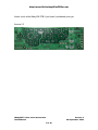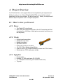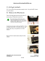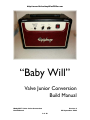
1
http://www.GuitarAmplifierPCBs.com
“Baby Will”
Valve Junior Conversion
Build Manual
“Baby Will” Valve Junior Conversion
Build Manual
Version 4
22 September 2009
1 of 36
http://www.GuitarAmplifierPCBs.com
1. Introduction
This manual contains instructions to convert an Epiphone Valve Junior guitar
amplifier to a roaring 18Watt amp modeled after the famed Marshall 1974X
circuit. The heart of it all is the “Baby Will”, a simplified version of Marshall’s
1974X amp known as the LiteIIb. The Baby Will takes the LiteIIb circuit and
conveniently lays it out in a printed circuit board, PCB, package.
This manual provides instruction for the assembly of version 2.3 of the Baby Will
circuit board. Several of the pictures or diagrams in this manual may refer to or
display a previous version of the circuit board. However, these still apply to the
current version.
To simplify things,
• The Epiphone Valve Junior will be referred to as EVJ, and
• The “Baby Will” 18 Watt LiteIIb PCB will be referred to as the Baby Will.
This manual guides you through the conversion which includes:
• removing the stock EVJ chassis from its cabinet,
• extracting the stock EVJ pcb,
• assembling the Baby Will,
• installation and hookup of the Baby Will into the EVJ chassis,
• initial power-up and testing, and
• reinstalling the chassis back into the EVJ cabinet to finish up the job.
“Baby Will” Valve Junior Conversion
Build Manual
Version 4
22 September 2009
2 of 36
http://www.GuitarAmplifierPCBs.com
Here’s a look at the Baby Will PCB if you haven’t purchased yours yet.
Version 2.3
“Baby Will” Valve Junior Conversion
Build Manual
Version 4
22 September 2009
3 of 36
http://www.GuitarAmplifierPCBs.com
2. Electrical Shock Warning
Building tube amplifiers involves working with, or around, high voltages. Working
inside a tube amplifier can be dangerous if you don't know the basic safety
practices. Building, modifying, or repairing tube amplifiers should only be
performed by trained personnel.
3. Disclaimer of Liability
GuitarAmplifierPCBs.com assumes no liability or responsibility, under any
circumstance, for personal injury or damage to property or personal property.
GuitarAmplifierPCBs.com reserves the right to make design changes or
improvements without obligation to revise prior versions.
All specifications are subject to change without notice.
“Baby Will” Valve Junior Conversion
Build Manual
Version 4
22 September 2009
4 of 36
http://www.GuitarAmplifierPCBs.com
Table of Contents
1.
2.
3.
4.
Introduction ............................................................................................................................. 2
Electrical Shock Warning ........................................................................................................ 4
Disclaimer of Liability .............................................................................................................. 4
Project Overview..................................................................................................................... 6
4.1
Here’s what you’ll need: ................................................................................................. 6
4.1.1
Parts: ..................................................................................................................... 6
4.1.2
Tools: ..................................................................................................................... 6
4.1.3
Supplies: ................................................................................................................ 6
5.
Let’s get started…................................................................................................................... 7
5.1
Remove the EVJ chassis ............................................................................................... 7
5.2
Remove the EVJ’s Stock Components .......................................................................... 8
5.2.1
Remove the Tubes and Tube Retainers ............................................................... 8
5.2.2
Remove the Output Transformer........................................................................... 8
5.2.3
Clean Up the Power Transformer........................................................................ 10
5.2.4
Remove the Volume Potentiometer .................................................................... 11
5.2.5
Remove the Stock EVJ Circuit Board.................................................................. 11
6.
Prepare the Chassis ............................................................................................................. 13
6.1
Layout and Drill ............................................................................................................ 13
6.1.1
Layout the Drill Plans........................................................................................... 13
6.1.2
Drilling the Chassis.............................................................................................. 14
7.
The Baby Will........................................................................................................................ 16
7.1
Assemble the Baby Will Circuit Board.......................................................................... 16
7.1.1
Tube Sockets....................................................................................................... 16
7.1.2
PCB Standoffs ..................................................................................................... 17
7.1.3
The Power Grid ................................................................................................... 17
7.1.4
Signal Path and Cathode Resistors .................................................................... 19
7.1.5
Sag Resistor ........................................................................................................ 19
7.1.6
Signal Path and Cathode Capacitors .................................................................. 20
7.1.7
Hum Balance ....................................................................................................... 20
7.1.8
Filter Capacitors and Ground Wire...................................................................... 21
7.1.9
Jumper Wires ...................................................................................................... 21
7.1.10
Input Jack Hookup............................................................................................... 22
7.1.11
Volume and Tone Controls.................................................................................. 25
8.
Putting it All Together............................................................................................................ 26
8.1
Install the New Components ........................................................................................ 26
8.1.1
The New Output Transformer.............................................................................. 26
8.1.2
The Baby Will PCB and Tube Hardware ............................................................. 28
8.1.3
Hookup the Leads to the Baby Will ..................................................................... 29
9.
Turn on the Power ................................................................................................................ 31
9.1
Check Your Work ......................................................................................................... 31
9.1.1
Take a Break ....................................................................................................... 31
9.1.2
Visual Inspection ................................................................................................. 31
9.2
Power Up without Tubes .............................................................................................. 32
9.2.1
The First Power Up.............................................................................................. 32
9.3
Power Up with Tubes ................................................................................................... 33
9.3
Power Up with Tubes ................................................................................................... 34
9.3.1
The Real Test ...................................................................................................... 34
11.
Finish Things Up............................................................................................................... 35
11.
Finish Things Up............................................................................................................... 36
11.1
Re-Assemble the Amp ................................................................................................. 36
“Baby Will” Valve Junior Conversion
Build Manual
Version 4
22 September 2009
5 of 36
http://www.GuitarAmplifierPCBs.com
4. Project Overview
You’ll find that this is a fun project that can be completed by an inexperienced
builder in a day or two. We at GuitarAmplifierPCBs.com wrote this manual
specifically for the novice builder. So anyone can do it. Really, it’s simple and it
doesn’t require expensive tools or complex equipment.
4.1 Here’s what you’ll need:
4.1.1 Parts:
•
•
The “Baby Will” circuit board
Misc. parts and components (refer to the VJ Conversion parts list
document for a full listing of what parts are needed and where you
can buy them)
4.1.2 Tools:
•
•
•
•
•
•
•
•
Phillips head screw driver
Standard screw driver
Needle nose pliers
Adjustable wrench
Power drill (corded or cordless)
1/8, 5/15, 3/8 in. Metal cutting drill bits
Unibit or punch (you’ll need something to make two 7/8 in. holes)
Soldering iron (15-40 watt power rating)
4.1.3 Supplies:
•
•
•
•
Fluxed solder
Roughly 3 ft. 600v rated wire (22-18 AWG)
¼” – 32 Spade connectors (you’ll need at least three)
Tag strip
“Baby Will” Valve Junior Conversion
Build Manual
Version 4
22 September 2009
6 of 36
http://www.GuitarAmplifierPCBs.com
5. Let’s get started…
OK. So you have all the parts and are ready to start. Let’s get that EVJ chassis
out of the cabinet.
5.1 Remove the EVJ chassis
Take off the back panel by removing the seven (7)
screws using a Phillips head screw driver.
Be careful pulling off the back panel.
They are typically stuck onto the chassis.
Slowly pull from each side to prevent the
tolex from lifting off the panel.
Locate the screw caps on the top of the EVJ. Using
a standard screw driver, the smaller the better, pry
up the caps until you can pull them out of their
sockets.
Remove the four chassis screws and pull out the
chassis.
“Baby Will” Valve Junior Conversion
Build Manual
Version 4
22 September 2009
7 of 36
http://www.GuitarAmplifierPCBs.com
5.2 Remove the EVJ’s Stock Components
A few of the stock EVJ parts have to be replaced. The tubes, tube retainers,
stock circuit board, and output transformer need to be removed.
5.2.1 Remove the Tubes and Tube Retainers
It’s as simple as:
• lift the tube retainer off the power tube,
• turn the retainer shield until the spring lifts the shield off the per-amp tube,
• pull the tubes out, and
• unclip the power tube retainer.
These items can be discarded. They will not be used later in the build.
Now that the tubes and their hardware have been
removed we can take a look inside. This is a version 2
EVJ. You can tell by the green board and the rectified
DC heater supply. Version 3s have a black board.
5.2.2 Remove the Output Transformer
To remove the output transformer,
disconnect its wire leads from the main
amp circuit board and the output jack
circuit board.
You don’t need to label the
leads since this output
transformer won’t be used
later in the build. However,
it’s recommended to label
them just in case you want
to use it in another build at a
later time.
Pull these two spade connectors from the main circuit board.
“Baby Will” Valve Junior Conversion
Build Manual
Version 4
22 September 2009
8 of 36
http://www.GuitarAmplifierPCBs.com
Unscrew the output jacks from the chassis and
separate the board from the chassis.
The board will be glued to the chassis. It
may require some extra work to pick the
glue off. Be careful not to damage the
board or the output jacks. They will be
reused later.
Flow the solder to each transformer
lead on the output jack board and pull
the lead out.
Remove the fastening nut at the star
grounding post and remove the output
board’s ground wire.
Clean up any remaining solder off the
board to assist in the installation of the
new transformer later in the build.
Now that all of the leads are free,
remove the mounting screws to
separate the transformer from the
chassis.
“Baby Will” Valve Junior Conversion
Build Manual
Version 4
22 September 2009
9 of 36
http://www.GuitarAmplifierPCBs.com
Here’s the output board and the output transformer
after removal. Set the output board aside. It will be
used later in the build.
The output transformer can be discarded. It will
NOT be used later in the build.
5.2.3 Clean Up the Power Transformer
The stock EVJ’s power transformer provides leads for various mains supply
voltages. The extra leads are fastened to dead posts on the stock circuit board
for storage. We are going to clean up the inside of the chassis by pulling any
unused power transformer leads outside of the chassis cavity.
Disconnect these three (3) leads from
the stock EVJ circuit board.
Version 1 and 2 EVJ will
have 12v secondary taps
tied off and tucked inside the
chassis. These need to be
pulled outside and secured
as well.
After the leads are all pulled outside
the chassis, bundle them together and
tie them off.
“Baby Will” Valve Junior Conversion
Build Manual
10 of 36
Version 4
22 September 2009
http://www.GuitarAmplifierPCBs.com
5.2.4 Remove the Volume Potentiometer
Unscrew the fastening nut from the volume
potentiometer.
Pull the volume pot back into the chassis. Leave it
connected to the stock EVJ circuit board.
The volume pot will be glued to the
chassis. This part will NOT be used later
in the build, so use whatever force you
need.
5.2.5 Remove the Stock EVJ Circuit Board
Disconnect these four (4) leads from
the stock EVJ circuit board.
Lift the ground wire from the star
ground post.
Unplug the input jack wire at the circuit
board.
Remove the six (6) screws fastening
the circuit board to the chassis.
“Baby Will” Valve Junior Conversion
Build Manual
11 of 36
Version 4
22 September 2009
http://www.GuitarAmplifierPCBs.com
Remove the stock circuit board and
pull all of the power transformer leads
to the rim of the chassis.
Salvage the ground wire from the
stock circuit board for use later.
Unscrew the input jack and remove it
from the chassis. Set it aside for use
later.
“Baby Will” Valve Junior Conversion
Build Manual
12 of 36
Version 4
22 September 2009
http://www.GuitarAmplifierPCBs.com
6. Prepare the Chassis
6.1 Layout and Drill
The Baby Will circuit board, tone potentiometer, and the new output transformer
require some drilling in the chassis.
6.1.1 Layout the Drill Plans
Always verify you are using the latest version of the drill plan posted on
GuitarAmplifierPCBs.com.
If you can not print onto 11x17” paper, you can take an electronic
version of the drill plan to Kinkos. They will print it professionally for
under $1.
Print out a copy of the VJ Conversion Drill Plan. Make sure it is printed to scale.
Cut away the unused
portion of the drill plan as
shown.
Align the drill plan to the
chassis using the
alignment holes
indicated on the plan.
Affix the plan to the
chassis with a generous
amount of tape or
Elmer’s white glue.
“Baby Will” Valve Junior Conversion
Build Manual
13 of 36
Version 4
22 September 2009
http://www.GuitarAmplifierPCBs.com
6.1.2 Drilling the Chassis
Start by setting the center of each hole to be drilled. A center punch is often
used. Here, a 1/16” drill
bit was used as shown in
the picture.
Use the appropriate drill
bit size as prescribed by
the drill plan.
Here, a unibit was used to drill out the 7/8” hole for the two (2) additional tube
socket holes.
Deburr or countersink
each hole to ensure no
sharp edges will cause
injury or component
failure.
“Baby Will” Valve Junior Conversion
Build Manual
14 of 36
Version 4
22 September 2009
http://www.GuitarAmplifierPCBs.com
Version 2.3 of the Baby Will circuit board was designed to use most of the stock
chassis mounted pcb standoffs. However, you need to remove one (1) standoff
for the board to fit.
Drill out and remove the stock standoff as shown in the picture below.
“Baby Will” Valve Junior Conversion
Build Manual
15 of 36
Version 4
22 September 2009
http://www.GuitarAmplifierPCBs.com
7. The Baby Will
7.1 Assemble the Baby Will Circuit Board
The anticipation has been killing you, hasn’t it? Finally, the assembly of the Baby
Will begins.
Did you check you make sure you have all of the
parts you’ll need to complete the assembly?
I wish I did.
7.1.1 Tube Sockets
The tube sockets get installed on
the back side of the board.
I repeat the back side of the
board.
Insert the tube sockets as shown.
They only go in one way (on the
back side).
Flip the board over and rest the sockets against your work bench/table. A piece
of cardboard is useful to hold the sockets in place when flipping the board over.
Slip the cardboard away when it’s resting on the bench. Check to make sure
each socket is properly seated. Then solder each leg of the sockets. The holes
are through plated so the solder will flow into the hole and through to the other
side of the socket leg creating a very durable connection.
“Baby Will” Valve Junior Conversion
Build Manual
16 of 36
Version 4
22 September 2009
http://www.GuitarAmplifierPCBs.com
7.1.2 PCB Standoffs
Install the one (1) PCB standoff on the back
side of the board in the location shown.
7.1.3 The Power Grid
Install the four (4) rectifier diodes.
Orient the diodes as indicated on the
circuit board. Bend the leads over,
insert them into the board, and bend
them to the side as shown. Solder
them to the board.
“Baby Will” Valve Junior Conversion
Build Manual
17 of 36
Version 4
22 September 2009
http://www.GuitarAmplifierPCBs.com
Trim the leads off at the top of each
solder pool.
Install, solder and trim all of the resistors in the power grid as shown. Refer to
the latest version of the schematic on GuitarAmplifierPCBs.com, the Baby Will
circuit board, and the component package to identify, locate and position
component values.
The filtering capacitors are not installed at this time. The height of these
capacitors interferes with the installation of the other components. These
capacitors will be the last component installed.
“Baby Will” Valve Junior Conversion
Build Manual
18 of 36
Version 4
22 September 2009
http://www.GuitarAmplifierPCBs.com
7.1.4 Signal Path and Cathode Resistors
Install, solder and trim all of the signal path and cathode resistors as shown.
Don’t bother with the input section. We’ll get to that later.
7.1.5 Sag Resistor
Install, solder and trim the sag resistor as shown.
“Baby Will” Valve Junior Conversion
Build Manual
19 of 36
Version 4
22 September 2009
http://www.GuitarAmplifierPCBs.com
7.1.6 Signal Path and Cathode Capacitors
Install, solder and trim all of the signal path and cathode capacitors as shown.
Make sure the 47uF cathode bypass capacitors are oriented with the polarities
indicated on the circuit board.
7.1.7 Hum Balance
Version 2.3 of the Baby Will circuit board is equipped with a DC elevated artificial
center tap. It uses two (2) 100 ohm 1% resistors to tie each lead of the tube
heater supply to the cathodes of the power tubes, which operate at around
10Vdc. This creates the DC elevated artificial center tap, which is a very
effective method for reducing audible hum in the amp.
Install, solder and trim the two (2) 100 ohm 1% resistors as shown below.
“Baby Will” Valve Junior Conversion
Build Manual
20 of 36
Version 4
22 September 2009
http://www.GuitarAmplifierPCBs.com
7.1.8 Filter Capacitors and Ground Wire
We can install the filter caps now that we have most of the components installed
on the board.
Insert the three (3) filter capacitors in their locations as indicated on the board.
These capacitors are polarized. Be careful to install them by inserting
the positive lead (the longer one) into the square pad and the negative
lead (as indicated by the downward arrow and “-“ symbol) in the round
pad.
Insert the ground wire that was removed from the stock EVJ circuit board in the
ground pad indicated on the Baby Will circuit board.
Solder and trim the leads.
7.1.9 Jumper Wires
Three jumper wires need to be installed. J1 and J2 are used to connect the
power rail across the heater traces. The third jumper is used to bypass the
standby switch.
Install, solder and trim the jumper wires as shown.
“Baby Will” Valve Junior Conversion
Build Manual
21 of 36
Version 4
22 September 2009
http://www.GuitarAmplifierPCBs.com
7.1.10 Input Jack Hookup
The input section of the Baby Will is designed to accommodate a variety of
configurations. The VJ Conversion only calls for one input jack. This requires a
jumper to tie the two input leads together so the two halves of V1 (12AX7) work
in parallel. The lead from R19 will be used to jumper the two inputs.
Bend the leads of the 1Meg resistor over as
usual and insert it into the R19 location.
From the back side of the board continue to
bend the top lead over and up through the
top solder pad of R22.
Here’s what it should look like from the front.
Insert the two (2) 10K in the R21 and R23 component locations.
Solder and trim the leads.
“Baby Will” Valve Junior Conversion
Build Manual
22 of 36
Version 4
22 September 2009
http://www.GuitarAmplifierPCBs.com
Prepare the stock input jack by cutting
off the stock connector.
Cut off the connector that
plugged into the stock EVJ
circuit board. Leave the
input connector plugged into
the input jack board.
Strip the insulation from the leads.
Insert the white lead into the input #1
(“IN-1”) pad and the black lead into a
ground pad. Solder and trim.
The input section is done.
“Baby Will” Valve Junior Conversion
Build Manual
23 of 36
Version 4
22 September 2009
http://www.GuitarAmplifierPCBs.com
Here’s what everything should look like so far - minus the input jack wiring.
Oops, this picture is missing the ground wire, too.
“Baby Will” Valve Junior Conversion
Build Manual
24 of 36
Version 4
22 September 2009
http://www.GuitarAmplifierPCBs.com
7.1.11 Volume and Tone Controls
To better understand how the volume and tone controls are wired, we
recommend that you study the VJ Conversion Chassis Layout and Schematic.
Cut the tab off of each of the pots with a pair of
cutters (side cuts). A pair of pliers can also be used
to bend the tab over and break it off.
We like to install the controls on the outside of the
chassis for better access.
Be careful with the soldering iron if you
temporarily install the pots on the outside of
the chassis. Fluxed solder will spit and
spatter onto the face of the chassis.
Here’s a picture of how the controls are configured. Sorry, the picture doesn’t
help much. It’s not the best work we’ve done.
The best resource is the layout diagram.
The volume and tone controls are connected to the Baby Will circuit board by
flying leads.
Remove the controls from the chassis and install the leads in the board.
Solder and trim the leads.
“Baby Will” Valve Junior Conversion
Build Manual
25 of 36
Version 4
22 September 2009
http://www.GuitarAmplifierPCBs.com
8. Putting it All Together
8.1 Install the New Components
Now that everything is out of the chassis that we don’t need, the chassis has
been drilled, and the Baby Will has been assembled, we can prep the chassis
and install all of the new components.
8.1.1 The New Output Transformer
Relocate the extra power transformer
grommet from the left-front to the new
hole drilled for the output transformer.
Guide the leads through the grommets
and seat the output transformer in
place. Position the output transformer
with its primary to the front and
secondary to the back as shown.
Guide all of the wires
through the chassis.
(Learn from our mistakes.)
The extra wires will be secured and
stowed inside the chassis. Their
location outside the chassis is too
susceptible to the heat from the tubes.
Secure the output transformer to the chassis using the stock fasteners.
“Baby Will” Valve Junior Conversion
Build Manual
26 of 36
Version 4
22 September 2009
http://www.GuitarAmplifierPCBs.com
Cut and solder the output transformer
leads onto the output jack board.
Refer to the
GuitarAmplifierPCBs.com
layout diagram, transformer
hookup diagram, and output
jack board for hookup
details.
Re-Install the output jack board into its
stock location.
Guide the ground wire from the output
jack board to the star grounding stud.
This will be secured to the stud later.
“Baby Will” Valve Junior Conversion
Build Manual
27 of 36
Version 4
22 September 2009
http://www.GuitarAmplifierPCBs.com
8.1.2 The Baby Will PCB and Tube Hardware
Lay the Baby Will down into the EVJ chassis with the tube sockets toward the
chassis and the diodes toward the power rocker switch. Align the standoffs with
their respective holes and fasten a screw into the standoff(s) near the power
transformer.
Do not tighten them down.
Install and fasten the volume and tone controls and the input jack into the chassis.
Slide the volume and tone knobs onto the pot stems and fasten with the set
screw.
It should look like this when you’re
done.
NOTE: Tube hardware is not required
for this build. The parts list
provides them for you. These
should be aligned, drilled, and
installed prior to installing the
circuit board.
Make sure the screws used to mount the tube hardware do not contact
the circuit board or any component on the inside of the chassis.
Here’s a closer look at the controls.
“Baby Will” Valve Junior Conversion
Build Manual
28 of 36
Version 4
22 September 2009
http://www.GuitarAmplifierPCBs.com
8.1.3 Hookup the Leads to the Baby Will
The board is installed in the chassis, but we still need to hook the high voltage
supply, heater element supply, and output transformer.
Guide the high voltage secondary leads to the T1 and T2 locations on the board.
Add some extra length (½” or 12mm) and cut the wires. Strip ¼” of the insulation
from the wire, twist the wire ends, and tin the end of the wire with some solder.
Insert one of the leads into T1. Insert the other into T2. Make sure the leads DO
NOT extend to far through the board and touch the metal chassis underneath.
Solder the leads into place from the top of the board.
Repeat the process described above for the heater and output transformer leads.
Here’s an image of all of the hookups installed and soldered into place.
Fasten the ground wires from the Baby Will circuit board and the output
transformer to the star ground screw post.
“Baby Will” Valve Junior Conversion
Build Manual
29 of 36
Version 4
22 September 2009
http://www.GuitarAmplifierPCBs.com
Here’s how it should look when everything is hooked up.
Good Job!
You’re almost done. But, before you start celebrating, you still have to review
your work, start it up and test the voltages.
“Baby Will” Valve Junior Conversion
Build Manual
30 of 36
Version 4
22 September 2009
http://www.GuitarAmplifierPCBs.com
9. Turn on the Power
9.1 Check Your Work
9.1.1 Take a Break
Now is a good time to take break. Rest your mind and gather your thoughts.
You don’t want to be tired or rushed while performing the following steps.
9.1.2 Visual Inspection
When you are ready, step through the instructions in this manual again and verify
each step was performed and completed properly.
Look for the following:
• Missing components
• Damaged components or leads
• Solder joints that may have spilled over onto a nearby component or
solder pad.
• Loose connections.
• Stray bits of wire from trimming wire and/or components.
• Components or wire leads shorting against each other or the chassis.
Pay special attention to the volume and tone controls.
•
•
Check that the IEC mains power connector is equipped with a good fuse.
The fuse should be rated for 2A Slo-Blo.
Check that the heater element supply (orange wires) is equipped with a
good fuse. The fuse should be rated for no more than 4A Slo-Blo.
“Baby Will” Valve Junior Conversion
Build Manual
31 of 36
Version 4
22 September 2009
http://www.GuitarAmplifierPCBs.com
9.2 Power Up without Tubes
9.2.1 The First Power Up
Make sure you are working is a safe area free of any flammable
chemicals or vapors. An assembly error may result in the emission of
sparks.
The tubes should NOT be installed during the initial power up.
Plug the amplifier into a speaker cabinet. Match the speaker
impedance with the appropriate output jack. Failure to connect a
speaker will cause harm and eventual failure of the output transformer.
These measurements will NOT match those on the schematic. These
are “As-Built” measurements. The actual voltages will be measured
after the tubes are installed and the circuit draws current.
Verify the amp’s power switch is in the “OFF” position. Insert the mains power
cord in the IEC mains connector.
Secure the black ground lead of your voltmeter to the chassis star ground lug.
Switch the amp’s power switch to the “ON” position. With your voltmeter, check
the following voltages. If a significant deviation from these readings is observed,
turn off the amp, unplug the mains power and investigate.
“Baby Will” Valve Junior Conversion
Build Manual
32 of 36
Version 4
22 September 2009
http://www.GuitarAmplifierPCBs.com
“Baby Will” Valve Junior Conversion
Build Manual
33 of 36
Version 4
22 September 2009
http://www.GuitarAmplifierPCBs.com
9.3 Power Up with Tubes
9.3.1 The Real Test
Install the tubes!
Aren’t they pretty?
These measurements WILL match those on the schematic.
Verify the amp’s power switch is in the “OFF” position. Insert the mains power
cord in the IEC mains connector.
Secure the black ground lead of your voltmeter to the chassis star ground lug.
Plug the amplifier into a speaker cabinet. Match the speaker
impedance with the appropriate output jack. Failure to connect a
speaker will cause harm and eventual failure of the output transformer.
Switch the amp’s power switch to the “ON” position. With your voltmeter, check
the following voltages. If a significant deviation from these readings is observed,
turn off the amp, unplug the mains power and investigate.
“Baby Will” Valve Junior Conversion
Build Manual
34 of 36
Version 4
22 September 2009
http://www.GuitarAmplifierPCBs.com
“Baby Will” Valve Junior Conversion
Build Manual
35 of 36
Version 4
22 September 2009
http://www.GuitarAmplifierPCBs.com
11. Finish Things Up
11.1 Re-Assemble the Amp
Slide the chassis back into the stock cabinet.
Fasten the chassis to the cabinet with the stock screws.
Insert the screw caps into the sockets.
Press them in until they are flush with the cabinet surface.
Attach the back panel with the stock screws.
Congratulations! Your Valve Junior is complete. Plug in a guitar and enjoy the
legendary tone of your 18 Watt LiteIIb “Baby Will” guitar amplifier.
“Baby Will” Valve Junior Conversion
Build Manual
36 of 36
Version 4
22 September 2009