1
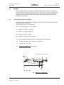
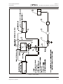
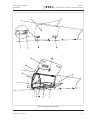
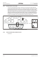
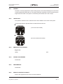
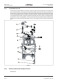
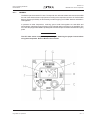
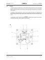
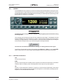
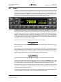
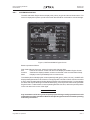
Pilot´s Operating Handbook
EXTRA 300LT
909.7
Section 909
ARTEX ME-406 ELT
SYSTEM DESCRIPTION
The ELT installation consists of the ELT unit and a buzzer, both fastened to the fuselage structure
aft of the back seat, an antenna located on the main fuselage cover behínd the cockpit, and a remote
switch with LED indication located on the instrument panel. The switch has the positions ARM and
ON.
909.7.1
SWITCH OPERATION
In a crash, an acceleration activated crash sensor (G-switch) turns the ELT ‘on’ automatically when
the ELT experiences a change in velocity (or deceleration) of 4.5 fps ±0.5 fps. Activation is also
accomplished by means of the cockpit mounted remote switch or the switch on the ELT. To
deactivate the ELT set either switch to the ‘ON’ position, then back to ‘ARM’.
The ELT does not have an ‘OFF’ position. Instead, a jumper between two pins on the front D-sub
connector must be in place for the G-switch to activate the unit. The jumper is installed on the mating
half of the connector so that when the connector is installed, the beacon is armed. This allows the
beacon to be handled or shipped without ‘nuisance’ activation (front connector removed).
NOTE
The ELT can still be manually activated using the local switch on the front of the ELT. Care should
be taken when transporting or shipping the ELT not to move the switch or allow packing material
to become lodged such as to toggle the switch.
909.7.2
SELF TEST MODE
Upon turn-off (from „ON“ back to „ARM“ state), the ELT automatically enters a self-test mode that
transmits a 406 MHz test coded transmission that monitors certain system functions before
returning to the ‘ARM’ mode. The transmission is ignored by any satellite that receives this signal,
but the ELT requires it to check output power and correct frequency. If the ELT is left activated for
approximately 50 seconds or more, a distress signal is generated that is accepted by the satellites.
In addition to 121.5 and 406 MHz signal integrity, other operating parameters are checked during
the self-test. Error codes are then generated if other problems are found. The error codes are
displayed by a series of „blinks“ of the ELT LED, remote LED and audio indicator. See „Installed
Transmitter Test“ section for more details and a description of the error codes.
NOTE
Any time the ELT is activated, it is transmitting a 121.5 MHz distress signal. Therefore, all
activations of the ELT should be kept to a minimum. Local or national regulations may limit testing
of the ELT or impose special requirements or conditions to perform testing. For the „self test“, Artex
recommends that the ELT be „ON“ for no more than 5 seconds. Testing should occur during the
first 5 minutes after the hour.
Page Date: 6. April 2010
909 - 5


![U.S. Version [Last Updated on: Jun 13th, 2014]](http://vs1.manualzilla.com/store/data/005873845_1-0370c7761d3b42576ec2ae1fd24c9e75-150x150.png)