1
30 MTR 20 WATT QRP
LINEAR AMPLIFIER KIT
Ramsey Electronics Model No.
QAMP30
Need a little extra boost for your QRP rig? Believe it or not, 20 watts is only
about an ‘S’ unit below a 100 watt rig! This nifty little amp will add some
“punch” to any QRP transmitter.
•
Works great with Ramsey QRP rigs or any other 1-2 watt
transmitters
•
Built-in T/R relay automatically switches between receive and
transmit
•
Runs on 12 volts DC at 2 to 4 amps; ideal for field day or battery
operation
•
Multistage low pass filter for a clean signal
•
Operates all modes: CW, SSB, or AM
•
Fast, easy, and fun 2 hour assembly
•
Informative manual answers questions on theory, hook-ups, and
uses - enhances resale value too!
•
Clear, concise assembly instructions carefully guide you to a
finished kit that works the FIRST time!
QAMP-30 • 1
RAMSEY TRANSMITTER KITS
• FM100B Professional FM Stereo Transmitter
• FM25B Synthesized Stereo FM Transmitter
• MR6 Model Rocket Tracking Transmitter
• TV6 Television Transmitter
RAMSEY RECEIVER KITS
• FR1 FM Broadcast Receiver
• AR1 Aircraft Band Receiver
• SR2 Shortwave Receiver
• SC1 Shortwave Converter
RAMSEY HOBBY KITS
• SG7 Personal Speed Radar
• SS70A Speech Scrambler
• BS1 “Bullshooter” Digital Voice Storage Unit
• AVS10 Automatic Sequential Video Switcher
• WCT20 Cable Wizard Cable Tracer
• LABC1 Lead Acid Battery Charger
• LC1 Inductance-Capacitance Meter
RAMSEY AMATEUR RADIO KITS
• DDF1 Doppler Direction Finder
• HR Series HF All Mode Receivers
• QRP Series HF CW Transmitters
• CW7 CW Keyer
• CPO3 Code Practice Oscillator
• QRP Power Amplifiers
RAMSEY MINI-KITS
Many other kits are available for hobby, school, Scouts and just plain FUN. New
kits are always under development. Write or call for our free Ramsey catalog.
QAMP30 QRP CW POWER AMPLIFIER KIT INSTRUCTION MANUAL
Ramsey Electronics publication No. MQAMP30 Revision 1.5b
First printing: January 1993
COPYRIGHT 1994 by Ramsey Electronics, Inc. 590 Fishers Station Drive, Victor, New York
14564. All rights reserved. No portion of this publication may be copied or duplicated without the
written permission of Ramsey Electronics, Inc. Printed in the United States of America.
QAMP-30 • 2
Ramsey Publication No. MQAMP30
Price $5.00
KIT ASSEMBLY
AND INSTRUCTION MANUAL
30 METER QRP
CW POWER
AMPLIFIER KIT
TABLE OF CONTENTS
Introduction to the QAMP30........... 4
How it works................................... 4
Parts list ......................................... 5
Tips and notes ............................... 6
QAMP30 assembly instructions ..... 6
Initial testing ..... ........................... 12
Verifying RF output power ........... 13
Troubleshooting tips..................... 15
Using the QAMP30 ...................... 16
Parts layout diagram .................... 17
Schematic diagram ...................... 18
Ramsey kit warranty .................... 19
RAMSEY ELECTRONICS, INC.
590 Fishers Station Drive
Victor, New York 14564
Phone (585) 924-4560
Fax (585) 924-4555
www.ramseykits.com
QAMP-30 • 3
INTRODUCTION
The Ramsey QAMP series of QRP power amplifiers are compact 10 to 20
watt RF amplifiers for QRP CW transmitters. These amplifiers are made to
be driven by transmitters in the ½ to 2 watt range. Built-in to the power
amplifier is a sensitive T-R relay which will switch the unit in and out of the
antenna line. When in receive, the amplifier is bypassed and the antenna
feeds directly to the input jack, when you go to transmit, the T-R circuit
detects the transmit RF power and automatically switches the power
amplifier into the circuit and amplifies the applied RF power. If you decide to
run "barefoot" turning off the QAMP will disable the amplifier and your QRP
transmitter will feed directly through the amplifier without any amplification.
Power is supplied by any 12 to 15 volt DC source with a current draw of 1 to
3 amps depending upon RF power output. A 5 pole low pass filter using
toroid cores keeps harmonics and spurious signals very low. The entire
amplifier is very easy to construct, but does require you to wind a few coils
and RF transformers - we'll lead you step-by-step through all steps!
HOW IT WORKS
The QRP amplifier is very simple with most of the "magic" being done by just
a few parts, the pair of MOSFET transistors and the ferrite wideband
transformers. Transformer T2 matches the 50 ohm amplifier input to the
push-pull inputs of the FET transistors. The term push-pull means that one
transistor amplifies the positive portion of the input signal while the other
transistor amplifier the negative portion - put another way, one is pushing
while the other is pulling! The center tapped transformer splits the input
signal so each transistor will only amplify the correct part of the input signal.
Incidentally, this push-pull technique has been used for years in both
vacuum tube and solid-state gear.
The push-pull signal output from the FETs is combined and impedance
matched to 50 ohms by ferrite transformer T1. To reduce any harmonic
content, a 5 pole low pass filter consisting of L1,2,3 and C4,5,6,7 is used.
The FET transistors are biased "on" slightly for best gain and linearity. Zener
diode D1 provides a constant voltage for the bias network R2,3,4. Bias pot
R4 allows adjustment of bias voltage to the FET transistor gates. It is
adjusted for a set amount of current through the transistors.
The T-R relay circuit uses a simple diode detector consisting of D2 and D3.
The detector output is amplified by transistors Q3 and Q4 to drive relay K1.
QAMP-30 • 4
PARTS LIST FOR THE QAMP30 QRP POWER AMPLIFIER
CAPACITORS:
1 100 to 220 µf electrolytic capacitor [C1]
1 10 µf electrolytic capacitor [C2]
4 .1 µf disc capacitor (marked .1 or 104) [C3,8,10,13]
2 330 ρf disc capacitor (marked 330 or 331) [C4,7]
2 560 ρf disc capacitor (marked 560 or 561) [C5,6]
2 .001 µf disc capacitor (marked .001 or 102 or 1000) [C11,12]
1 .01 µf disc capacitor (marked .01 or 103 or 10 nf) [C9]
RESISTORS:
3 1 K ohm resistor (brown-black-red) [R1,5, TP1]
1 6.8 K ohm resistor (blue-gray-red) [R2]
2 10 K ohm resistor (brown-black-orange) [R3,12]
1 470 ohm resistor (yellow-violet-brown) [R6]
1 100 K ohm resistor (brown-black-yellow) [R7]
2 270 ohm resistor (red-violet-brown) [R8,9]
1 51 ohm resistor (green- brown-black) [R10]
1 2.2 K ohm resistor (red-red-red) [R11]
1 5 K potentiometer (marked 502M) [R4]
SEMICONDUCTOR DEVICES:
1 Zener diode, 6.2 volt (gray body with black band) [D1]
2 1N4148 type signal diode (glass body with black band) [D2,3]
1 1N4002 style black epoxy diode [D4]
2 Power MOSFET transistor (marked P16NF06) [Q1,2]
2 2N3904 NPN transistor [Q3,4]
1 221334 PNP transistor [Q5]
OTHER COMPONENTS:
1 Relay DPDT 12 volt [K1]
1 PC mount pushbutton switch [S1]
2 RCA style PC mount phono jacks [J1,2]
1 2.5 mm DC power jack [J3]
2 Heatsink [HS1,2]
3 Yellow toroid coil core [L1,2,3]
1 10 µH inductor [L4]
1 2 hole small ferrite transformer core [T2]
1 2 hole large ferrite transformer core [T1]
7' #24 enameled magnet wire (thin wire) [for winding L1,2,3 and T1,2]
2 4-40 x ¼” machine screw
2 4-40 hex nut
REQUIRED, NOT SUPPLIED:
Ramsey case, knob and panel set, Ramsey part no. CQRP
Matching input and output cables to existing QRP transmitter
12 volt DC power supply 3 amp rating
Proper dummy load or resonant antenna
QAMP-30 • 5
"THE RAMSEY LEARN-AS-YOU-BUILD ASSEMBLY STRATEGY"
Take a look at the parts layout diagram. There is quite a lot to the construction
of the QAMP30. It's easier than it seems once you get going, especially after
you have installed a few of the "landmark" components. Once these
"landmark" components are placed, other parts’ positions are referenced to
them, and construction goes quite smoothly. This will help in relating from one
part to another what specific holes it may require on the board, and that part's
orientation. In addition, we will discuss the purpose of most components or
groups of components as we go along. This is the Ramsey Learn-As-YouBuild kit assembly philosophy. Be sure to read through all the steps, and
check the boxes as you go to be sure you didn't miss any important steps.
Most of the problems we find here at the factory are due to faulty assembly, no
matter how experienced the builder may be: it’s especially tough to tell a 30
year experienced ham that he goofed! Before you run the circuit, check all
diodes and polarized capacitors for proper orientation.
TIPS AND NOTES:
Use a good soldering technique - let your soldering iron tip gently heat the
traces to which you are soldering. Heat both wires and pads simultaneously.
Apply the solder on the iron, lead, and the pad when pad and wire is hot
enough to melt the solder. The actual joint should look like a drop of water on
paper (somewhat soaked in).
Parts are mounted on the top side of the board. This is the side that has no
traces or pads on it.
Part orientation - All parts in this kit are mounted at 90 degree angles, meaning
parts are either parallel or perpendicular to the sides of the board.
Part installation - When parts are installed, the part is placed flat to the board,
and the leads are bent on the backside of the board to prevent the part from
falling out before soldering. The part is then soldered into place, and the spare
leads are removed. Make sure lead lengths are as short as possible when
dealing with the RF section of this kit.
CONSTRUCTION:
Since you may appreciate some "warm-up" soldering practice as well as a
chance to put some "landmarks" on the PC board, we'll first install some
"hardware" components.
In all the following instruction steps, our word "INSTALL" means to do the
following:
•
Insert the part, oriented correctly, into its correct holes in the PC board.
QAMP-30 • 6
•
•
•
If helpful, gently bend the part’s wire leads or tabs to hold it in
place, with the body of the part snugly against the top side
(component side) of the PC board.
Solder all wires or pins of the part, whether the 2 wires of a resistor
or the 3 or 4 wires of a transistor.
Trim all excess wires extending beyond each solder connection,
taking care that wire trimmings do not become lodged in PC board
solder connections.
1. Install S1, PC mount pushbutton switch. Solder all 6 pins securely.
2. Install J1and J2, PC mount RCA phono jacks. Solder all 4 pins on each
securely as these connectors will be subjected to some stress when coax
cables are connected to them.
3. Install J3, PC mount DC power jack.
4. Install relay K1. Notice that it installs only one way.
5. Install potentiometer R4. This pot allows adjustment of the bias to the
power transistors.
6. Install C9, .01 µf disc capacitor (marked .01 or 103 or 10 nf).
7. Install Q5, 221334 PNP transistor; orient the flat side toward D2.
8. Install R6, 470 ohm resistor (yellow-violet-brown).
9. Install R10, 51 ohm resistor (green-brown-black).
10. Install R11, 2.2 K ohm resistor (red-red-red).
11. Install R12, 10 K ohm resistor (brown-black-orange).
12. Install D2 and D3, 1N4148 style signal diodes (glass body with black
band). Pay special attention to the banded ends. The banded end on a
diode is the cathode and must be oriented correctly or the circuit will not
work. Both diode D3 and diode D2 are detectors for sensing applied RF
power.
13. Install C10, .1 µf disc capacitor (marked .1 or 104).
14. Install R7, 100 K ohm resistor (brown-black-yellow).
15. Install Q3 and Q4, 2N3904 NPN transistors, observing proper
orientation of the flat side. These two transistors amplify the signal diode's
output to a level high enough to close relay K1.
QAMP-30 • 7
16. Install diode D4, 1N4002 style black epoxy diode. Check positioning
of the banded end.
17. Install jumper JMP2. Use a piece of scrap component lead wire bent
into a "staple" shape and inserted into the board like a component.
Jumpers act as electronic "bridges" carrying signals over PC board circuit
traces underneath.
18. Install C13, .1 µf disc capacitor (marked .1 or 104).
19. Install L4, 10 µH inductor (green body with brown-black-black bands).
20. Install R3, 10 K ohm resistor (brown-black-orange).
21. Install C2, 10 µf electrolytic capacitor. Electrolytic capacitors are
polarized with a ( + ) and a ( - ) lead and must be installed correctly for
proper operation. Generally, capacitors have their ( - ) lead marked with a
black stripe while PC boards have the ( + ) hole indicated.
22. Install D1, 6.2 volt Zener diode (gray body with a black band). This
diode provides a stable voltage which is used to provide bias for the
power transistors.
23. Install R5, 1 K ohm resistor (brown-black-red).
24. Install R2, 6.8 K ohm resistor (blue-gray-red).
25. Install R1, 1 K ohm resistor (brown-black-red).
26. Locate another 1 K ohm resistor (brown-black-red). Trim back one
lead to a length of ¼ inch. Bend this wire into a small loop as shown. This
loop will act as a convenient point to connect a test probe for setting the
bias voltage. Insert the resistor into the PC board and hold it carefully
while you solder it to the board.
27. Install R8, 270 ohm resistor (red-violet-brown).
28. Install C11, .001 µf disc capacitor (marked .001 or 102).
29. Install R9, another 270 ohm resistor (red-violet-brown).
30. Install C12, another .001 µf disc capacitor (marked .001 or 102).
31. Install C8, .1 µf disc capacitor (marked .1 or 104).
QAMP-30 • 8
These last four parts (R8,9 and C11,12) form parasitic suppression networks
across each transistor to suppress any tendency for high frequency oscillation
in the power amplifier.
32. Install C3, another .1 µf disc capacitor (marked .1 or 104). Both of
these capacitors bypass the center tap of the ferrite transformers to
ground. Bypass means to provide a low impedance path to ground.
33. Install C1, 100 to 220 µf electrolytic capacitor. Be sure to observe
correct polarity.
34. Install C4, 330 ρf disc capacitor (marked 330 or 331).
35. Install C5, 560 ρf disc capacitor (marked 560 or 561).
36. Install C6, another 560 ρf disc capacitor (marked 560 or 561).
37. Install C7, another 330 ρf disc capacitor (marked 330 or 331).
38. Install wire jumper, JMP1. Use a scrap piece of component lead wire.
Transistor bend pix
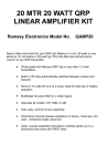
39. Locate the MOSFET power transistors and prepare the leads for
insertion into the PC board. Bend down the two outside leads about 1/8"
from the transistor body and the center lead about 3/16" from the body.
40. Mount the transistors and heatsinks to the PC board using the 4-40
screws and nuts. Solder all transistor leads. Note that the heatsinks
may look slightly different from the ones shown.
QAMP-30 • 9
We're almost finished. All we need to do now is install a few remaining parts that
have to be handmade - for that "old-world craftsmanship" touch! We'll prepare
all those parts now for further assembly. We give you plenty of enameled wire,
but if you mess up, you can get a whole 50' spool of it from Radio Shack.
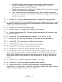
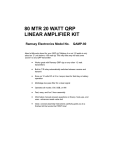
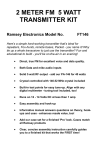
41. Winding L1 and L3 toroid RF coils (two identical units ): Locate 2 of the
donut shaped yellow toroid cores provided in the kit. Cut 10" of the
enameled magnet wire and, following the drawing, thread the wire through
the core 15 times - not 14, not 16; it MUST be 15 times through the core,
pulling each turn gently tight. Winding too tightly runs the risk of scraping
off the enamel insulation and shorting the wire. Tin each end with solder by
holding your soldering iron and solder the wire ends until the insulation
melts away and the copper wire underneath coats nicely with solder. Tin all
the way up to the toroid core body.
15 turns through center of core
IMPORTANT:
Loop the first winding
around the front of the
core as shown.
42. Winding L2: Locate the remaining yellow toroid core and cut 11" of
enameled magnet wire. Wind 16 turns through the core using the same
procedure as above. Tin the wire ends as before. Mark this part with a piece
of tape, a dab of paint or a magic marker. We don't want to confuse it with
the other two toroid coils wound just before!
16 turns through center of core
IMPORTANT:
Loop the first winding
around the front of the
core as shown.
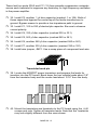
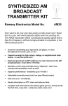
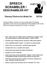
43. Winding T2: Locate the smaller of the two 2-hole ferrite cores. Cut off
one 11 inch length of enameled magnet wire and thread the wire through
the core 6 times, pulling each turn gently tight. That's 6 times through each
hole, resulting in 6 complete whole turns through the core. Be especially
careful not to strip the insulation by pulling too tightly around the core. The
QAMP-30 • 10
amount of wire cut for this task is the proper amount. If you have too little
or too much, then you have not wound the core correctly. Tin each end with
solder as before. Tin all the way up to the core body. This winding is the
primary of transformer T2.
Only 2 turns shown for clarity, 8
turns are needed
Each lead is about 1” long
44. Cut off another length of wire, 8 inches long. Wind 1 turn through the
core, loop out 1 inch, twist together and run one more turn through the
core, continuing on in the same direction as before. Tin each end with
solder all the way up to the core body. This winding is the 2 turn centertapped secondary of T2.
Primary leads
(wound previ-
6 turns previously wound
(not all turns shown for clar-
1” long leads
Twist the loop together tightly
(not shown tightly for clarity)
1 turn with loop then
another turn
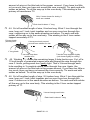
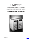
45. Winding T1: Locate the remaining larger 2-hole ferrite core. Cut off a
10 inch length of enameled magnet wire and thread the wire through the
core 3 times, pulling each turn gently tight. That's 3 times through each
hole resulting in 3 complete whole turns through the core. Again, the
amount of wire cut for this task is the proper amount. If you have too little or
too much, then you have not wound the core correctly. Tin each end with
solder as before. Tin all the way up to the core body.
46. Cut off another length of wire, 9½ inches long. Wind 1 turn through the
core, loop out 1 inch, twist together and run one more turn through the
core. Continue on in the same direction as before. Tin each end with solder
all the way up to the core body. This winding is the 2 turn center-tapped
primary of T1.
3 turns through each hole
Each lead is about 1” long
QAMP-30 • 11
Secondary leads
(wound previously)
1 turn with loop then
another turn
Twist the loop together tightly
(not shown tightly for clarity)
47. Locate the smaller transformer (T2) and install it snugly on the PC
board.
48. Install the larger transformer (T1) into the indicated location on the PC
board.
49. Install L1, a 15 turn toroid inductor wound previously. If desired, a
small dab of hot melt glue, bathtub sealer, or caulk may be used to secure
the toroids.
50. Install L2, the 16 turn toroid inductor - you marked it, remember?
51. Install L3, the remaining 15 turn toroid inductor.
This completes the assembly of your QRP power amplifier. Now's a good time
to give your masterpiece a good going over, being especially alert for any:
• bridged-over solder joints;
• misplaced components;
• transistors or diodes placed wrong;
• electrolytic capacitors installed wrong.
INITIAL TESTS:
To prepare your amplifier for testing you'll need the following:
• 1. Multimeter capable of measuring voltage and current.
• 2. 12 volt DC power source of at least 3 amp capacity.
• 3. Suitable dummy load and resonant antenna.
• 4. QRP transmitter with a power output in the ½ to 2 watt range,
such
as the Ramsey QRP-30.
• 5. Proper cables to interface between the QRP transmitter and the QRP
power amplifier.
With the above all set up and handy, let's get testing!.
1. Rotate Bias pot R4 fully CCW.
2. Connect a multimeter to TP1 ; set the meter to read up to 5 volts DC.
QAMP-30 • 12
3. Connect a dummy load to J1, the amplifier RF output. In a pinch, a
light bulb may be used - see the section, "Verifying RF Power Output."
4. Temporarily install a jumper from the collector of Q3 to ground.
5. Apply power to the amplifier but do not turn on the transmitter.
Measure the current drawn by the amplifier and slowly rotate the bias pot,
R4, clockwise until you reach a reading of ¼ amp. Do not allow the current
to rise above ½ amp. If you cannot adjust or reduce the current,
disconnect the power supply and consult the troubleshooting hints section.
The voltage at TP1 should be about 3.2 to 3.5 volts.
6. Turn off power. Disconnect jumper from Q3 to ground.
7. Connect the QRP transmitter to the input of the amplifier. Key the
transmitter. You should hear the T-R relay click and see amplified power
output. Measure the DC current draw; it should be in the 1 to 3 amp range
depending upon power output. Unkey the transmitter. The relay should
drop out and the current should drop back down to ¼ amp
This completes the testing of your QRP power amplifier. The PC board should
be mounted into a protective enclosure to guard against accidental contact.
The Ramsey CQAMP case set provides an ideal perfectly sized cabinet that
matches all other Ramsey kits.
Study the following sections on DC power supply and RF power
considerations. Operate your transmitter with good amateur practice.
YOUR POWER SUPPLY AND RF OUTPUT POWER
For optimum performance, one or two volts of extra DC supply power can
make quite a difference in any RF power amplifier. For example, two lantern
batteries in series, or 8 D cells, will obviously provide about 12 volts with
sufficient current capability for casual operating. For maximum RF output
power, use a supply of 13 to 14 volts DC. The easiest method is to place two
fresh D cells in series with your power source if a full 13.6 - 15 volts DC is not
available. Be aware that batteries are not the optimum power source,
especially if you are prone to long QSOs! A word of caution concerning wall
plug style AC adapter power supplies: They are not suitable for operation of
your amplifier due to their poor regulation, AC ripple content, and RFI
susceptibility.
With 1 watt of drive and a supply voltage in the 11-12 volt range, you can
expect a 1 to 2 amp current draw and about 10 watts of RF output power. With
a solid 13 to 14 volt supply, you can expect about 2 to 3 amps current draw
and up to 10 or 12 watts of RF output power. With 2 watts of RF drive, expect
up to 20 watts RF output!
QAMP-30 • 13
VERIFYING TRANSMITTER RF OUTPUT
The most important thing to know is whether your transmitter is delivering some
measurable and reassuring level of RF power. Then you can continue on to
adding the QRP amplifier and checking out the whole set-up.
Ideally, you have a small RF wattmeter, already inserted in the antenna line,
capable of accurately measuring low output power in watts. And it cost you less
than what you paid for the transmitter kit. Right? In the words of Wayne from
"Wayne's World"... Not! So here are a few other ideas for you to try.
Saying the same thing another way, we assume you know that accurate,
commercially built RF wattmeters cost much more than what you paid for this
Ramsey amplifier kit. Since this solid-state amplifier does not require lots of
critical tuning or adjustments, a periodic power output check-up should suffice. If
you do not own or have access to a low-level RF power meter, use a trick that is
decades old - the common flashlight or panel bulb. All you need to know is the
basic differences between bright, superbright, dim, unlit and burned out! Using a
light bulb to check power output is also a satisfying way to put Ohm's Law to
work. Your Radio Shack catalog specifies operating voltage and current in
milliamperes for a variety of small replacement lamps and a local automobile
parts store is a treasure trove of various other lamps. It may be worth your while
to make up a simple plug-in "output tester" for your amplifier - a male RCA plug
connected to a socket for the bulb of your choice or even soldered directly to the
bulb.
RF voltage levels in this amplifier can vary from 2 to 25 volts RMS depending on
various factors. Typically, 1 watt power levels are achieved in the 5 to 7 volts
RMS range, 5 watts at 12 to 15 volts, and 10 watts at 20 to 25 volts. A good test
bulb for this amplifier is the #93 automobile lamp bulb or the #1156 type bulb.
Both are 12.8 volt rated, with the #93 being specified at 1 amp and the #1156
being 2 amps for normal brilliance. Using some Ohm's law calculations shows
that the #93 is a 12 watt lamp and the #1156 is a 24 watt lamp. We can conclude
that 10 watts or so of RF should light a #93 bulb reasonably well, while 20 watts
should be about right for a #1156. Try it out!
Please remember, though, that a flashlight bulb does NOT present the proper
load impedance to the amplifier output, so theoretical calculations based on the
bulb`s rating can only be approximate. For example, the #93 at full brilliance
presents a 12 ohm load to the amplifier. Because of this, the amplifier may act
"flakey" when tuning up into a light bulb, and by all means you should not
consider a light bulb an accurate indicator of the QAMP-30's performance! If
ANY light bulb lights up when connected to the antenna jack of this amplifier,
you can be satisfied that you have RF output power at least equal to the DC
power rating of the bulb you are using. If you burn out your bulb, rejoice and put
your rig on the air!
QAMP-30 • 14
Amateur radio magazines and handbooks provide a variety of circuits for RF
wattmeters and relative field-strength indicators, including methods of using
your VOM as an indicating device. CQ magazine for March 1990 offers an
article by KB4ZGC on how to make a highly accurate yet inexpensive dummy
load and wattmeter capable of showing 1/10-watt differences in RF power. If
you use a wattmeter characterized for the HF frequency region, it will not give
accurate results at the much higher two meter frequencies, although it will be
quite adequate for go/no-go testing.
MAXIMIZING RF POWER OUTPUT
The simplest way to ensure maximum reasonable power output without
component damage is to run the DC voltage in the 13 to 14 volt range,
observing a maximum limit of +15VDC. Typically, an automobile power source
is 13.6 volts when the engine is running, and most mobile rigs are specified at
this voltage level.
IMPORTANT NOTE: If you are experimenting with this transmitter and see a
sudden and massive increase in power output and DC current, you have not
reached the promised land or created a 100 watt amplifier! Sudden surges like
that are a sure sign of amplifier self-oscillation. Kill the DC power supply
immediately because your RF power transistors are heading to selfdestruction while probably interfering with every TV set in the neighborhood! A
poorly matched antenna along with higher supply voltages is usually
responsible for this occurring. Any prolonged "parasitic" emissions may also
overheat and destroy other components in the amplifier.
TROUBLESHOOTING HINTS
The QRP power amplifier is very straight forward and simple to troubleshoot.
When beginning to track down a problem, use some common sense to narrow
down your search area.
If the amplifier is not keying upon application of RF power, check to see if the
T-R relay circuitry is operating. A quick read-over of the theory of operation
tells us the diode detector senses the RF and a pair of transistors amplifies
the signal to activate the T-R relay. Proper logic tells us to: 1) First check and
see if RF is getting to the diodes; 2) see if they are detecting RF; 3) see if the
transistors are driving the relay. Proper procedure is to take just one part of
the circuit at a time and follow the signal through.
If the amplifier does not amplify, check to see if RF is flowing through to
transformer T2 and across to the RF power transistors. Amplified output
should appear at output transformer T1 and then on to the low pass filter.
Remember that RF enters and exits through relay contacts on K1.
Do the transistors get too hot? Do they get hot without amplifying? Things to
check are the bias circuitry and RF path through the relay. The amplifier
should draw about ¼ amp with no signal applied. If you see more than that,
recheck the bias setting (see the section "INITIAL TESTS").
QAMP-30 • 15
If you hear an AC hum on the transmitted signal, usual causes are RF getting
back into the power supply or a bad VSWR on the antenna.
These short checks in no way detail any and all problems that can rear their
ugly head, but should get you on the way to solving most errors. We'd like to
be able to foresee a problem a builder may encounter, but the sheer number
of parts and the permutations and combinations of installing them makes any
list of precise, exact solutions impossible. If you run into a roadblock, gather all
your thoughts and information and give a call to the factory for some help. If
you elect to enlist the help of a local expert, great...but be sure the expert is
qualified (no need for having someone lead you down the wrong path)!
Remember: You may always return the kit for factory service, and there's no
charge if the problem is our fault. See the warranty on the last page of this
manual.
USING THE QRP POWER AMPLIFIER
Hooking up and using the amplifier is easy: Just connect your existing
transmitter to the QAMP input and the antenna to the QAMP output. A
resonant antenna is an absolute requirement for QRP operation, and an
amplifier is not a "band-aid" for a poor antenna system!
For maximum performance, a QRP station must include the following:
1 A resonant antenna (dipole or quarter-wave vertical);
2 Good quality coaxial feedline and connectors;
3 An effective earth ground.
We cannot expect good results from low levels of RF output if the power gets
wasted in lousy coax, corroded connections, or poor antennas.
If you elect to use an antenna tuner, it is extremely important that you
understand exactly how to use tuners and what they can and cannot do. A few
watts of RF can easily become lost in an incorrectly adjusted antenna
matching device. The whole idea of a QRP station is to keep things simple and
economical, so we cannot overemphasize the priority of a clean, efficient
connection of the amplifier output to a resonant antenna.
ENCLOSURE RECOMMENDATIONS
Your finished amplifier can be installed in a variety of enclosures of your own
design and choosing. You might be planning to combine several Ramsey
circuit kit boards in a single enclosure. Use of the inexpensive and attractive
Ramsey case and hardware set will give your unit that nice finished look and
increase its resale value. These sturdy black instrument cases are supplied
with neatly lettered front and rear panels, switch knobs, rubber feet and
mounting screws.
QAMP-30 • 16
While we believe that the Ramsey enclosure and knob option is a fine value
for finishing off your Ramsey kit, we are happy to give you a couple of
additional suggestions and our reasons for them. If your first goal is economy
and rugged portability, you will find that the circuit board can be mounted
nicely in a standard VHS videotape storage box, which also gives room for
storing cables, a small homemade keyer, etc. The controls are easily mounted
at one end of such a box. It may be necessary to cut away the molded posts
which secure the tape itself. These storage boxes come in several styles, so
pick one which truly looks practical as a project enclosure. To accomplish RF
shielding, the most economical metal enclosure nicely suited for Ramsey
amateur kit board is Radio Shack No. 270-253A. This metal utility cabinet can
accommodate both a receiver, transmitter and amplifier board, plus speaker,
with room for various refinements you might like to add.
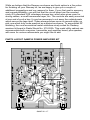
PARTS LAYOUT QAMP30 POWER AMPLIFIER KIT
QAMP-30 • 17
QAMP-30 • 18
The Ramsey Kit Warranty
Amateur radio magazines and handbooks provide a variety of circuits for RF
wattmeters
relativeBEFORE
field-strength
indicators,
including
methods
of using
Please readand
carefully
calling
or writing
in about
your kit.
Most
your
VOM as
indicating
device. CQ
magazine
forfactory.
March 1990 offers an
problems
cananbe
solved without
contacting
the
article by
Notice that this is not a "fine print" warranty. We want you to understand your rights and ours too! All
Ramsey kits will work if assembled properly. The very fact that your kit includes this new manual is your
assurance that a team of knowledgeable people have field-tested several "copies" of this kit straight from
the Ramsey Inventory. If you need help, please read through your manual carefully, all information
required to properly build and test your kit is contained within the pages!
1. DEFECTIVE PARTS: It's always easy to blame a part for a problem in your kit, Before you conclude
that a part may be bad, thoroughly check your work. Today's semiconductors and passive components
have reached incredibly high reliability levels, and its sad to say that our human construction skills have
not! But on rare occasions a sour component can slip through. All our kit parts carry the Ramsey
Electronics Warranty that they are free from defects for a full ninety (90) days from the date of purchase.
Defective parts will be replaced promptly at our expense. If you suspect any part to be defective, please
mail it to our factory for testing and replacement. Please send only the defective part(s), not the entire kit.
The part(s) MUST be returned to us in suitable condition for testing. Please be aware that testing can
usually determine if the part was truly defective or damaged by assembly or usage. Don't be afraid of
telling us that you 'blew-it', we're all human and in most cases, replacement parts are very reasonably
priced.
2. MISSING PARTS: Before assuming a part value is incorrect, check the parts listing carefully to see if it
is a critical value such as a specific coil or IC, or whether a RANGE of values is suitable (such as "100 to
500 uF"). Often times, common sense will solve a mysterious missing part problem. If you're missing five
10K ohm resistors and received five extra 1K resistors, you can pretty much be assured that the '1K ohm'
resistors are actually the 'missing' 10 K parts ("Hum-m-m, I guess the 'red' band really does look orange!")
Ramsey Electronics project kits are packed with pride in the USA. If you believe we packed an incorrect
part or omitted a part clearly indicated in your assembly manual as supplied with the basic kit by Ramsey,
please write or call us with information on the part you need and proof of kit purchase.
3. FACTORY REPAIR OF ASSEMBLED KITS:
To qualify for Ramsey Electronics factory repair, kits MUST:
1. NOT be assembled with acid core solder or flux.
2. NOT be modified in any manner.
3. BE returned in fully-assembled form, not partially assembled.
4. BE accompanied by the proper repair fee. No repair will be undertaken until we have received the
MINIMUM repair fee (1/2 hour labor) of $25.00, or authorization to charge it to your credit card account.
5. INCLUDE a description of the problem and legible return address. DO NOT send a separate letter;
include all correspondence with the unit. Please do not include your own hardware such as non-Ramsey
cabinets, knobs, cables, external battery packs and the like. Ramsey Electronics, Inc., reserves the right
to refuse repair on ANY item in which we find excessive problems or damage due to construction
methods. To assist customers in such situations, Ramsey Electronics, Inc., reserves the right to solve
their needs on a case-by-case basis.
The repair is $50.00 per hour, regardless of the cost of the kit. Please understand that our technicians are
not volunteers and that set-up, testing, diagnosis, repair and repacking and paperwork can take nearly an
hour of paid employee time on even a simple kit. Of course, if we find that a part was defective in
manufacture, there will be no charge to repair your kit (But please realize that our technicians know the
difference between a defective part and parts burned out or damaged through improper use or assembly).
4. REFUNDS: You are given ten (10) days to examine our products. If you are not satisfied, you may
return your unassembled kit with all the parts and instructions and proof of purchase to the factory for a
full refund. The return package should be packed securely. Insurance is recommended. Please do not
cause needless delays; read all information carefully.
QAMP-30 • 19
QAMP30 20 WATT LINEAR AMPLIFIER
Quick Reference Page Guide
Introduction to the QAMP-30 ..........4
How it works ...................................4
Parts list ..........................................5
QAMP-30 assembly instructions.....6
Initial testing ..... ............................12
Verifying RF output power ............13
Using the QAMP-30 ......................16
Parts layout diagram .....................17
Schematic diagram .......................18
Ramsey kit warranty .....................19
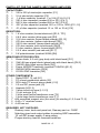
REQUIRED TOOLS
• Soldering Iron Ramsey WLC100
• Thin Rosin Core Solder Ramsey RTS12
• Needle Nose Pliers Ramsey MPP4 or RTS05
• Small Diagonal Cutters Ramsey RTS04
<OR> Technician’s Tool Kit TK405
ADDITIONAL SUGGESTED ITEMS
Holder for PC Board/Parts Ramsey HH3
Desoldering Braid Ramsey RTS08
Digital Multimeter Ramsey M133
•
•
•
Price: $5.00
Ramsey Publication No. MQAMP30
Assembly and Instruction manual for:
RAMSEY MODEL NO. QAMP30 30 METER 20 WATT
RAMSEY ELECTRONICS, INC.
590 Fishers Station Drive
Victor, New York 14564
Phone
(585) 924-4560
Fax
(585) 924-4555
QAMP-30 • 20
www.ramseykits.com
TOTAL SOLDER POINTS
121
ESTIMATED ASSEMBLY
TIME
Beginner .............. 4 hrs
Intermediate......... 2 hrs
Advanced ............. 1.5 hrs