1
Ramsey Electronics Model No.
R2XL1
Have you ever found yourself with two RCA outputs on your
audio equipment and you somehow have to connect them to
XLR inputs. While wiring RCA levels directly to XLR can work,
the levels will be way too low! So what do you do?
Here is the answer to your conversion dilemma. The R2XL1 not
only converts your connection types from RCA to XLR, it also
gives you the added advantage of independent channel gain
control for the proper levels!
•
Powered by a 12VAC wall power transformer for ground isolation.
•
Stereo/Mono switch so you can drive a stereo device with a mono
source.
•
Variable gain settings from 0.2 to 20.2 for full control with
independent left and right adjustments. Lets you get your levels
perfect!
•
Low noise design fully regulated for the best sound possible.
•
10 Hz to 50 kHz audio pass-band for clear, crisp sound.
•
Durable male XLR converters for heavy repeated use.
R2XL1 • 1
RAMSEY TRANSMITTER KITS
• FM100B Professional FM Stereo Transmitter
• FM25B Synthesized Stereo FM Transmitter
• MR6 Model Rocket Tracking Transmitter
• TV6 Television Transmitter
RAMSEY RECEIVER KITS
• FR1 FM Broadcast Receiver
• AR1 Aircraft Band Receiver
• SR2 Shortwave Receiver
• SC1 Shortwave Converter
RAMSEY HOBBY KITS
• SG7 Personal Speed Radar
• SS70A Speech Scrambler
• BS1 “Bullshooter” Digital Voice Storage Unit
• AVS10 Automatic Sequential Video Switcher
• WCT20 Cable Wizard Cable Tracer
• LABC1 Lead Acid Battery Charger
• IG7 Ion Generator
• CT255 Compu Temp Digital Binary Thermometer
• LC1 Inductance-Capacitance Meter
RAMSEY AMATEUR RADIO KITS
• DDF1 Doppler Direction Finder
• HR Series HF All Mode Receivers
• QRP Series HF CW Transmitters
• CW7 CW Keyer
• CPO3 Code Practice Oscillator
• QRP Power Amplifiers
RAMSEY MINI-KITS
Many other kits are available for hobby, school, Scouts and just plain FUN. New
kits are always under development. Write or call for our free Ramsey catalog.
R2XL1 KIT INSTRUCTION MANUAL
Ramsey Electronics publication No. MR2XL1 Rev 1.3
First printing: June 2001
COPYRIGHT 2001 by Ramsey Electronics, Inc. 590 Fishers Station Drive, Victor, New York
14564. All rights reserved. No portion of this publication may be copied or duplicated without the
written permission of Ramsey Electronics, Inc. Printed in the United States of America.
R2XL1 • 2
Ramsey Publication No. MR2XL1
Price $5.00
KIT ASSEMBLY
AND INSTRUCTION MANUAL FOR
R2XL1 RCA TO XLR LEVEL
CONVERTER KIT
TABLE OF CONTENTS
Introduction .......................................... 4
Circuit Description................................. 4
Parts List ............................................... 7
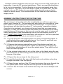
Schematic Diagram .............................. 8
Parts Layout Diagram ........................... 9
Learn as You Build ............................. 10
Assembly ............................................ 12
Using the R2XL1................................. 15
Professional Audio Wiring................... 16
Custom Case Assembly ..................... 17
Troubleshooting .................................. 18
Warranty ............................................. 19
RAMSEY ELECTRONICS, INC.
590 Fishers Station Drive
Victor, New York 14564
Phone (585) 924-4560
Fax (585) 924-4555
www.ramseykits.com
R2XL1 • 3
INTRODUCTION
Welcome to another quality kit brought to you by Ramsey Electronics, Inc.
This kit was designed to allow you to connect consumer audio devices to professional equipment with as little hassle as possible. You would think that a
product like this was readily available, but it isn’t. Now you can easily go between a standard CD player and a studio style mixer, or even run a professional stereo transmitter directly from your computer!
It’s true that with the correct wiring that you can easily connect consumer audio devices to professional equipment. The problem however is that the resulting levels are way too low! The R2XL1 provides plenty of gain so that you can
bring consumer levels of 0.7V RMS up to the required 1.228V RMS used by
studio style devices. This required a gain of 1.228 / .7 or 1.75 to achieve. We
expanded that by over 10 times giving you an adjustable gain range of 0.2 to
20.2! This gives you plenty of control to get those levels just right (especially
when coming from a computer or portable CD player).
A very simple circuit in principle, the R2XL1 uses two quad FET input
opamps to get the needed gain as well as giving you the required +- balanced
outputs to drive low impedance XLR inputs.
Another nice feature we added was the Stereo/Mono switch. It takes the audio presented on the right input and sends it to both left and right XLR amplifiers when pressed in. This allows you to drive a professional stereo audio device from a monaural audio source with a press of a button.
CIRCUIT DESCRIPTION
The R2XL1 is an audio pre-amplifier that offers the user a wide range of adjustable output levels. To analyze this circuit we will first follow the signal path
from input to output and then take a close look at the power supply section.
The power supply performs a nifty trick in order to get an additional supply rail
from a single power source so we’ll take the time to discuss it.
Looking at J1, the dual RCA connector. Notice that the signal first goes
through a couple of 10 uF capacitors. These capacitors are called coupling
caps because they filter out any DC on the line while letting the AC signal (the
music) pass through. Removing any residual DC component that might be
present makes sure there will be no interference with the first amplification
stages. For now we will only look at the top half of the circuit which handles
the right channel audio path.
Following the first coupling capacitor we see R13, a 10K resistor to ground.
This serves the purpose of making sure the opamp stage side of the preamp
will always be at the ground potential. This is a common practice that helps to
reduce the likelihood of power pops and switching transients when you plug
and unplug your audio cables.
R2XL1 • 4
The next component in line is R4. This 1K resistor in combination with R3
and R5 sets the gain of the first inverting opamp stage (U1:C). An inverting
opamp will take the signal presented on its input and flip the polarity of the signal on its output giving you the inverse value of the original. In our case, the
resulting output signal from the opamp (pin 8) will be opposite in polarity to
that of the original input signal on the left hand side of R4. The amplitude of
the signal will also change depending on the gain of the circuit. The formula
for determining the gain in this circuit is given by Av = -Rf / Ri, where Ri is the
input resistance of R4 and Rf is the feedback resistance of R3 + R5 together.
If we want to find the maximum gain of this stage, we can take our 1,000 (1K)
ohm input resistor and divide its value by our 10,000 (10K) ohm pot and 100
ohm feedback resistors added together (10,100 or 10.1K ohms). This works
out to a maximum gain of -10.1 (the negative value just means it is inverted).
How does this affect our signal? Take for example a +1V input present at R4.
Multiply the input signal value by the calculated gain factor (+1V x -10.1) to
obtain -10.1 volts on the output (pin 8) of the amplifier. That wasn’t so hard
was it?
Let’s move on. The signal output from pin 8 (U1:C) then goes through two
more opamp stages (U1:A and U1:B) for processing before we’re done! One
of these stages has a familiar topology. Take a look at U1:B. It’s another inverting opamp using resistors of R1 and R2 to set its gain. Use the formula
from before to figure out for yourself what the gain has been set for. We’ll confirm in a moment if you are correct.
The other opamp (U1:A ) is configured as a non-inverting amplifier. A noninverting opamp does just what it sounds like, it preserves the original signal
polarity while offering the ability to amplify the signal (increase or decrease its
amplitude). The formula for determining the gain of this configuration is given
by Av = 1+ Rf / Ri, where Ri is the input resistance (0 ohms), and Rf is the
feedback resistance (0 ohms). Since there are no input or feedback resistors,
the gain works out to be 1 for this stage. This type of circuit is commonly
called a Voltage Follower (for obvious reasons) and it acts as a buffer.
Both stages U1:A and U1:B have their gain set to 1 and –1 respectively (did
you get –1 for the gain of the inverting amplifier?). Because one opamp is inverting and the other is not, their outputs are always opposite of one another.
The end results is a combined gain of 2 for these two opamps together. How
does that work? Let’s analyze this. If the output of our first stage (U1:C) is +1
volt (to make the math easy) and it is amplified by the inverting amplifier (U1:
B) with a gain of –1, its output will be –1 Volt. When the same 1V input is applied to the non-inverting stage (U1:A) with a gain of 1, its output will be 1 Volt.
Looking across the outputs of both amps (pins 1 and 7) the difference between the two works out to be 1 - (-1) = 2 Volts. Hey… that’s pretty neat!
Armed with the information that our first stage (U1:C) has a maximum gain
of 10.1 and the second stage (U1:A and U1:B) has a fixed gain of 2, we can
R2XL1 • 5
determine that the total gain of the circuit is 20.2 by multiplying the series gain
values together (10.1 x 2). This gives us plenty of control to get our low level
RCA signals up to the higher XLR requirements.
This may be more than you ever wanted to know about a preamplifier design, but we aren’t done yet! The output of the two opamps in the last stage
are sent through another set of coupling capacitors that removes any DC component we may have accidentally added when we amplified the audio. It also
helps us to isolate our preamplifier from any DC present from a poorly designed audio component that you may plug this into. We use larger 100 uF
capacitors here because XLR specifications say we need to drive down to 560
ohm impedances. The larger capacitors help us to preserve our low frequency
information. (The left channel works exactly the same as the right so take a
look at the schematic and apply your new found knowledge.)
All that seems fine with a stereo audio source, but how do you handle one
that is Mono? The mode selection switch (S1) allows you to take the right
channel audio input and send it simultaneously through both the left and right
amplifier stages for dual outputs are the right levels!
Now on to the power supply! Since we are going to run this product from a
12VAC power transformer we will need to convert the AC supply to a DC voltage in order for our opamps to work properly. To accomplish this, we use a
bridge rectifier consisting of D1-4 to take the AC input voltage and convert it to
positive DC pulses. This directly is too noisy for our application so C12 was
added to smooth things out. C12 acts like a battery and holds the voltage at a
more consistent level to get rid of the pulses (also called ripple). Since C12 is
a very small “battery” (it discharges almost as quickly as it charges) so some
of the pulses are still present. To eliminate these we use a voltage regulator to
completely smooth out the remaining pulses. The output of VR1 is our positive
supply and is completely smooth and ready to use.
So where do we get the negative supply from? Simple, we use a voltage
doubler scheme. This works by using a coupling capacitor C11 in a bit different fashion. Here we are isolating the DC component of the positive half of the
supply and leaving only the AC component. This AC component is then rectified by D5 and D6 into negative pulses. The negative pulses are then
smoothed by C13 into a negative supply source with a bit of ripple. To remove
the remaining pulses we use a negative voltage regulator (VR2) to completely
smooth it out. There you go, our negative supply!
At this point we have two regulators VR1 and VR2 with outputs of +12V
and –12V respectively. This means we have plenty of supply voltage for our
opamps to work with. Usually opamps can have maximum output of 1.4 volts
within their supply voltage so our opamps will go from +10.6V to –10.6V giving
you a 21.2 Volt total swing! More than enough to drive XLR inputs with plenty
of dynamic range. Ok, I think it is time to start building our kit!
R2XL1 • 6
RAMSEY R2XL1 PARTS LIST
Semiconductors
6
1
1
2
1N4002 Rectifier Diodes (D1, 2, 3, 4, 5, 6)
78L12 +12V Voltage Regulator (VR1)
79L12 –12V Voltage Regulator (VR2)
LF347N Quad FET opamps (U1, 2)
Resistors
2
6
2
2
2
10K ohm potentiometers (R5, 11)
1K ohm resistors (brown-black-red) (R1, 2, 4, 7, 8, 10)
10K ohm resistors (brown-black-orange) (R13, 14)
100 ohm resistors (brown-black-brown) (R3, 9)
560 ohm resistors (green-blue-brown) (R6, 12)
Capacitors
2
4
4
3
0.01 uF Ceramic capacitors (marked 103) (C9, 10)
10 uF Electrolytic capacitors (C1, 4, 7, 8)
100 uF Electrolytic capacitors (C2, 3, 5, 6)
470 uF Electrolytic capacitors (C11, 12, 13)
Miscellaneous
2
2
1
1
Male PC Mounted XLR connectors (J2, 4)
DPDT push button switches (S1, 2)
2.5 mm AC Power jack (J6)
Dual RCA connector (J1)
R2XL1 • 7
R2XL1 • 8
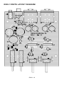
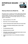
R2XL1 PARTS LAYOUT DIAGRAM
R2XL1 • 9
RAMSEY “LEARN-AS-YOU-BUILD” ASSEMBLY STRATEGY
Be sure to read through all of the steps and check the boxes as you go along
to be sure you don't miss any. Although you may be in a hurry to see results,
before you switch on the power check all wiring and capacitors for proper
orientation. Also check the board for any possible solder shorts and/or cold
solder joints. All of these mistakes could have detrimental effects on your kit,
not to mention your ego!
Kit building tips:
Use a good soldering technique. Let your soldering iron tip gently heat the
traces to which you are soldering making sure to heat both the leads and the
pads simultaneously. Apply the solder to the the pad when the junction is hot
enough to melt the solder. The finished joint should look like a drop of water on
paper, somewhat soaked in.
Mount all electrical parts on the top side of the board provided. The top side is
clearly marked with a white silkscreen showing the part numbers, you can’t
miss it. This is the side that has little or no traces on it, but is covered with
mostly copper. When parts are installed, the part is placed flat to the board, and
the leads are bent on the backside of the board to prevent the part from falling
out before soldering (1). The part is then soldered securely to the board (2-4),
and the remaining lead length is then clipped off (5). Notice how the solder joint
looks on close up, clean and smooth with no holes or sharp points (6).
R2XL1 • 10
We sincerely hope you put this kit together by carefully following the directions. This project will not work as well as you wished if you just slap it together
without following good assembly techniques and all of the instructions. No
matter how clear we may think our manual is, if you have any questions give us
a call at the factory instead of jumping to conclusions. We will be happy to help
you with any problems.
Keep in mind that we want to mount all the parts AS LOW AS POSSIBLE to
the board. A 1/4” lead length on a resistor not mounted close to the board can
act as an inductor or an antenna causing all sorts of problems in your circuit.
The components don’t need to be squished to the board, just keep them as
close as possible to the board.
For each part, our word "Install" always means these steps:
1. Pick the correct part value to start with.
2. Insert it into the correct PC board location, making sure the part is
mounted flush to the PC board unless otherwise noted.
3. Orient it correctly, follow the PC board drawing and the written directions
for all parts - especially when there's a right way and a wrong way to solder
it in. (Diode bands, electrolytic capacitor polarity, transistor shapes, dotted
or notched ends of IC's, and so forth.)
4. Solder all connections unless directed otherwise. Use enough heat and
solder flow for clean, shiny, completed connections.
Keeping this in mind, lets begin by sorting out our components and crosschecking them against the parts list to make sure we have received everything.
NOTE TO NEWCOMERS: If you are a first time kit builder you may find this
manual easier to understand than you may have expected. Each part in the kit
is checked off as you go, while a detailed description of each part is given. If
you follow each step in the manual in order, and practice good soldering and kit
building skills, the kit is next to fail-safe. If a problem does occur, the manual
will lead you through step by step in the troubleshooting guide until you find the
problem and are able to correct it.
R2XL1 • 11
R2XL1 ASSEMBLY
We will start with the lowest profile components first and then work our way
up to the largest. We do this to make assembly much easier since fitting a
short component between two big ones can be a real pain.
1. Install D1, one of the 1N4002 diodes (black body with white stripe
marked 1N4002). Note that diodes can only conduct in one direction so
part orientation is critical! The diode will have a white stripe indicating the
cathode end while the parts layout diagram shows a black stripe indicating
the same. Make sure and put the part in the same way as shown!
2. Install D3, another 1N4002 diode. Again pay close attention to orientation
3. Install D2, a 1N4002 diode. Check orientation!
4. Install D4, the last 1N4002 diode to make up the bridge rectifier to give
us out positive supply! Pay attention to orientation again.
5. Install D6, another 1N4002 diode. Orientation must be correct or we will
get no negative supply! Note how this is placed between two large capacitors. Imagine trying to install this after the capacitors were soldered in.
Good thing you follow directions.
6. Install D5, the last 1N4002 diode. Again check orientation.
7. Install R8, a 1K ohm resistor (brown-black-red).
8. Install R9, a 100 ohm resistor (brown-black-brown).
9. Install R10, a 1K ohm resistor (brown-black-red).
10. Install C10, a 0.01 uF ceramic capacitor (marked 103).
11. Install R7, a 1K ohm resistor (brown-black-red).
12. Install C9, another 0.01 uF ceramic capacitor (marked 103).
13. Install U2, one of the LF347 quad opamps. Note that the layout diagram shows a dimple on the end, this indicates pin 1. Your actual part
may have this same dimple or a dot near pin one. When installing ICs, it is
sometimes easy to have a pin bent underneath the part, make sure all
pins are through before soldering. Always double check your part’s orientation before soldering all the pins!
R2XL1 • 12
14. Install R1, a 1K ohm resistor (brown-black-red).
15. Install R2, a 1K ohm resistor (brown-black-red).
16. Install R3, a 100 ohm resistor (brown-black-brown).
17. Install R4, a 1K ohm resistor (brown-black-red).
18. Install U1, the other LF347 quad opamp. Again make sure you orient it
correctly! It is in the same orientation as the last part. Dimple indicates the
pin 1 end. Check to make sure all pins are through, then solder all 14 pins!
19. Install C7, a 10 uF electrolytic capacitor. Note that electrolytic capacitors are polarity sensitive. This means they wont work if put in the wrong
way! That is why we have indicators on the layouts indicating the positive
side of the capacitor. Usually the capacitor itself is marked on the negative
side. We don’t do this to confuse you, but that has been the standard for
years so we aren’t about to change it now. Just make sure that the side
NOT marked negative is in the same side marked positive on the board.
20. Install C8, another 10 uF electrolytic capacitor. Again check polarity.
21. Install R14, a 10K ohm resistor (brown-black-orange).
22. Install R13, another 10K ohm resistor (brown-black-orange).
23. Install C4, a 10 uF electrolytic capacitor. Note orientation!
24. Install C1, another 10 uF electrolytic capacitor. Make sure the negative
pin is not in the positive hole!
25. Install C6, a 100 uF electrolytic capacitor. Again note orientation for
this and all of the rest of your electrolytic capacitors! This will save you
from having to read “orientation” six more times.
26. Install C5, another 100 uF electrolytic capacitor.
27. Install C3, a 100 uF electrolytic capacitor.
28. Install C2, a 100 uF electrolytic capacitor.
29. Install VR1, the 78L12 +12 regulator. Yes, this looks like a transistor
but it’s not. In fact has many transistors and a special Zener diode inside.
Make sure the flat side of the part is installed as shown on the diagram.
R2XL1 • 13
30. Install VR2, the 79L12 negative –12V regulator. Again make sure and
install it with the orientation shown on the diagram.
31. Now it is time to install the larger components. We will begin with the
jacks. Install J2, one of the PC mounted XLR connectors. You must be
careful when installing these parts that all the leads go in the respective
holes. For example there is a little pin in the middle of the bottom which is
used to ground the cable case. This can easily get bent over. Make sure
all of the pins are through the holes before soldering. Also make sure to
solder the mounting pins.
32. Install J4, the other XLR connector.
33. Install J1, the dual RCA connector. Make sure the part is flush when
soldering for good mechanical soundness.
34. Install J6, our 2.5 mm AC power jack.
35. Install C11, a 470 uF electrolytic capacitor. Check orientation! (just in
case you forgot!)
36. Install C12, another 470 uF electrolytic capacitor.
37. Install C13, the last 470 uF electrolytic capacitor.
38. Install S2, the power switch. Make sure it is flush to the board before
soldering!
39. Install S1, the Stereo/Mono switch. Again make sure it is flush before
soldering.
40. Install R11, one of the 10K ohm potentiometers. Solder the mounting
pins as well as the electrical contacts for good mechanical stability.
41. Install R5, the other 10K ohm potentiometer.
You may note we left R12 and R6 out of the assembly process. This is because more often than not they are not needed. You can install them at some
future time if you find they are necessary to reduce noise and interference in
extremely long cable runs. We recommend you leave them out for now to ensure better sound quality.
R2XL1 • 14
At this point it is time to go back through and check your assembly methods
for:
•
Diode orientation. Make sure the cathode and (the line) is in the same orientation as shown on the assembly diagram.
•
Electrolytic capacitor orientation. Make sure the negative side of the capacitors are not in the positively marked holes!
•
IC orientation. Let’s hope you did this right, they are hard to move once
soldered!
•
Check for cold solder joints. Make sure all connections look nice and
clean. If in question re-heat and apply a bit more solder.
•
Check for solder bridges. We have seen some that look just like a trace
was supposed to be there, so check thoroughly for potential shorts!
Well, it looks like it is time to hook up our peripherals and give our newly
completed kit a test!
USING THE R2XL1
The operation is pretty straight forward but want to give you one bit of advise
so that you won’t get frustrated. Don’t use your R2XL1 as your primary audio
gain control! Since we built in a lot of gain it is too difficult to adjust on the fly.
Even worse, there are two controls to tweak making it even harder to keep
these at the same setting at the same time. Set these once and leave them
alone. In fact you may want to put a marking on them so you can tell at a
glance if someone messes them up on you.
The last thing we need to mention is the labeling of the panels for the case
set. This would normally be started by a statement sounding like “A funny
thing happened on the way to the print house…”. There are regretfully two errors on the labels that come with the case set, one on the front and one on the
back. The front panel Stereo/Mono mode selection switch is backwards and
the rear panel RCA Audio Input jacks are labeled backwards. We are sorry for
the inconvenience but this is usually a set it and forget it type of product.
Keep in mind from the Circuit Description section, Mono mode operation requires feeding your audio source into the Right RCA input (labeled Left on the
rear panel… sorry).
Set your levels as needed and your off to the races!
R2XL1 • 15
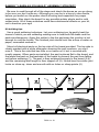
PROFESSIONAL AUDIO WIRING
You would think it would be easy to connect professional audio equipment
together, but unfortunately it’s not. There can be all sorts of issues that come
up; usually it is AC line hum in your equipment you have to deal with. This is
normally caused by ground loops in the equipment. This effect can be caused
by only a very little current and can wind up having a tremendous impact on
your sound and sanity. We will try to clear some issues up for you by showing
you how to properly wire XLR connectors and what to do in case of hum.
Audio Outputs:
XLR connectors provide a balanced connection that rejects common mode
noise for a cleaner audio signal. Make sure your XLR connectors are WIRED
CORRECTLY! Some manufacturers make them incorrectly so you may want
to check the connectors and re-make them to standards if necessary. Current
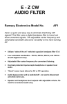
standards dictate that XLR connectors should be wired as follows:
Ground = pin 1, White = Pin 2, Black = Pin 3. Sometimes you will find red
instead of white. Both ends of the cable are wired in the same order, per the
following diagram.
FEMALE
2
3
1
WHITE
BLACK
2 Conductor Shielded Cable
SHIELD(GND)
MALE
WHITE
BLACK
SHIELD(GND)
2
3
1
Across pins 2 & 3 of the XLR inputs look for +4 dBu (1.228VRMS) as
equivalent to 0 dBuV. The audio output can deliver up to a maximum of 21.2V
pk/pk, but then you have to scale the level back down with your audio gain to
get acceptable sound in your destination equipment.
Solving ground loop hum:
We don’t expect you to come across this, but if you do, here is what you may
do.
1. Try running a wire to connect the chassis of your destination equipment
to the source equipment AND the R2XL1. If all are grounded well together, it may prevent the ground loop from traveling down the audio cables.
2. Try lifting the shield wire on your XLR cable on the FEMALE end (the
one that plugs into your R2XL1). This will eliminate the path of the
ground loop.
R2XL1 • 16
If neither of these methods works and you have a source of RF nearby like a
transmitter, it may be RF causing interference. This is a more difficult problem
to fix, but not impossible. The first thing to do is move equipment away from
the RF source. The next is to put the R2XL1 inside of a metal case. The last
method is to use RF chokes on your audio cables (usually snap-on ferrite
beads of various sizes). You should be able to find these at most electronic
supply stores.
ASSEMBLY INSTRUCTIONS FOR CUSTOM CASE
The enclosure is a key element to the overall pride you will have upon completing your Ramsey kit. The enclosure will show how you were able to “build
from scratch” a commercial piece of high-tech electronics. For some of us,
the enclosure will also hide a number of “not-so-pretty” assembly mistakes.
Once the kit is enclosed, your friends will never know that you were new to
soldering. Finally, the enclosure case will protect your electronics from many
possible causes of damage so that you can receive years worth of enjoyment
using, talking about, and remembering the fun you had building your kit. In
short, TAKE YOUR TIME when assembling the enclosure. This is the part that
you and your friends will look at and admire for years!
1. Lay the front and rear plastic plates over their corresponding labels to
verify which sticker goes with which panel. You’ll want to work with one
panel at a time to avoid possible mix-ups.
2. Remove the backing material from one of the stickers and line it up
properly on its pre-punched panel. Make sure that they are aligned correctly before allowing them to touch the plastic plates. They stick the first
time; line them up right!
3. Use a sharp hobby knife to cut out the holes in the labels along the prepunched holes. A short sawing motion works well around the inner circumference of the holes.
4. Repeat the above steps for the other panel.
5. Insert the board into the case with the knobs and switches extending
through the holes in the front panel.
6. Raise the rear portion of the PC board and extend the jacks through the
rear plastic plate. Insert the plate into the grooves on the base tray.
7. Secure the PC board to the bottom base tray with 4 short Phillips head
screws.
R2XL1 • 17
TROUBLESHOOTING
PROBLEM: I have no audio gain, in fact it only attenuates!
SOLUTION: You will need a voltmeter to check your power. Look at pin 4 of
U1 for +12 volts, and pin 11 for –12 volts. It may not be exactly that voltage,
but +- 0.5 volts if fine. Without power applied the R2XL1 will pass through audio, but not much.
PROBLEM: Sound is very badly distorted.
SOLUTION: You may be using a high level source into the R2XL1 causing it
to overload. Using this to convert from speaker lever to XLR is not recommended but it is possible. Just turn down your volume a bit. Also check that
you do not have the gain up all the way. Lastly, check to make sure your destination equipment is set up correctly.
PROBLEM: Audio seems noisy or picking up interference.
SOLUTION: Here is where R6 and R12 come into play. The two 560 ohm
(green-blue-brown) resistors that were left out of the normal construction steps
may need to be installed. With long cable runs you are more likely to run into
this type of problem. We left these parts out initially to help increase the overall frequency response of the unit and provide you with a much crisper sound.
You may need to install them however to combat the effects of long cable
runs.
(Note to wired and tested customers: By default, these are installed on the
wired and tested versions of the kit already.)
PROBLEM: It just wont work, it must be Ramsey’s fault!
SOLUTION: Look in the warranty section for information how to contact us
and to find out about our free services when it is our fault. We would recommend however that you go through the assembly steps SLOWLY and check
for potential mistakes. If that fails, give us a call and we’ll be happy to help.
R2XL1 • 18
The Ramsey Kit Warranty
Please read carefully BEFORE calling or writing in about your kit. Most problems can be
solved without contacting the factory.
Notice that this is not a "fine print" warranty. We want you to understand your rights and ours too!
All Ramsey kits will work if assembled properly. The very fact that your kit includes this new manual
is your assurance that a team of knowledgeable people have field-tested several "copies" of this kit
straight from the Ramsey Inventory. If you need help, please read through your manual carefully.
All information required to properly build and test your kit is contained within the pages!
1. DEFECTIVE PARTS: It's always easy to blame a part for a problem in your kit, Before you
conclude that a part may be bad, thoroughly check your work. Today's semiconductors and passive
components have reached incredibly high reliability levels, and it’s sad to say that our human
construction skills have not! But on rare occasions a sour component can slip through. All our kit
parts carry the Ramsey Electronics Warranty that they are free from defects for a full ninety (90)
days from the date of purchase. Defective parts will be replaced promptly at our expense. If you
suspect any part to be defective, please mail it to our factory for testing and replacement. Please
send only the defective part(s), not the entire kit. The part(s) MUST be returned to us in suitable
condition for testing. Please be aware that testing can usually determine if the part was truly
defective or damaged by assembly or usage. Don't be afraid of telling us that you 'blew-it', we're all
human and in most cases, replacement parts are very reasonably priced.
2. MISSING PARTS: Before assuming a part value is incorrect, check the parts listing carefully to
see if it is a critical value such as a specific coil or IC, or whether a RANGE of values is suitable
(such as "100 to 500 uF"). Often times, common sense will solve a mysterious missing part
problem. If you're missing five 10K ohm resistors and received five extra 1K resistors, you can
pretty much be assured that the '1K ohm' resistors are actually the 'missing' 10 K parts ("Hum-m-m,
I guess the 'red' band really does look orange!") Ramsey Electronics project kits are packed with
pride in the USA. If you believe we packed an incorrect part or omitted a part clearly indicated in
your assembly manual as supplied with the basic kit by Ramsey, please write or call us with
information on the part you need and proof of kit purchase.
3. FACTORY REPAIR OF ASSEMBLED KITS:
To qualify for Ramsey Electronics factory repair, kits MUST:
1. NOT be assembled with acid core solder or flux.
2. NOT be modified in any manner.
3. BE returned in fully-assembled form, not partially assembled.
4. BE accompanied by the proper repair fee. No repair will be undertaken until we have received
the MINIMUM repair fee (1/2 hour labor) of $25.00, or authorization to charge it to your
credit card account.
5. INCLUDE a description of the problem and legible return address. DO NOT send a separate
letter; include all correspondence with the unit. Please do not include your own hardware
such as non-Ramsey cabinets, knobs, cables, external battery packs and the like. Ramsey
Electronics, Inc., reserves the right to refuse repair on ANY item in which we find excessive
problems or damage due to construction methods. To assist customers in such situations,
Ramsey Electronics, Inc., reserves the right to solve their needs on a case-by-case basis.
The repair is $50.00 per hour, regardless of the cost of the kit. Please understand that our
technicians are not volunteers and that set-up, testing, diagnosis, repair and repacking and
paperwork can take nearly an hour of paid employee time on even a simple kit. Of course, if we find
that a part was defective in manufacture, there will be no charge to repair your kit (But please
realize that our technicians know the difference between a defective part and parts burned out or
damaged through improper use or assembly).
4. REFUNDS: You are given ten (10) days to examine our products. If you are not satisfied, you
may return your unassembled kit with all the parts and instructions and proof of purchase to the
factory for a full refund. The return package should be packed securely. Insurance is
recommended. Please do not cause needless delays, read all information carefully.
R2XL1 • 19
R2XL1 RCA TO XLR LEVEL CONVERTER KIT
Quick Reference Page Guide
Introduction .......................................... 4
Circuit Description ................................. 4
Parts List ............................................... 7
Schematic Diagram .............................. 8
Parts Layout Diagram ........................... 9
Assembly ............................................ 12
Using the R2XL1 ................................. 15
Professional Audio Wiring ................... 16
Troubleshooting .................................. 18
Warranty ............................................. 19
REQUIRED TOOLS
• Soldering Iron Ramsey WLC100
• Thin Rosin Core Solder Ramsey RTS12
• Needle Nose Pliers Ramsey MPP4 or RTS05
• Small Diagonal Cutters Ramsey RTS04
<OR> Technician’s Tool Kit TK405
ADDITIONAL SUGGESTED ITEMS
• Holder for PC Board/Parts Ramsey HH3
• Desoldering Braid Ramsey RTS08
• Digital Multimeter Ramsey M133
Price: $5.00
Ramsey Publication No. MR2XL1
Assembly and Instruction manual for:
TOTAL SOLDER POINTS
153
RAMSEY ELECTRONICS, INC.
590 Fishers Station Drive
Victor, New York 14564
Phone (585) 924-4560
Fax (585) 924-4555
R2XL1 • 20
www.ramseykits.com
ESTIMATED ASSEMBLY
TIME
Beginner .............. 2.0 hrs
Intermediate......... 1.5 hr
Advanced ............. 1.0 hr