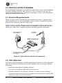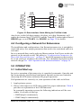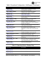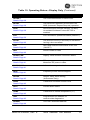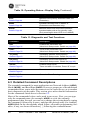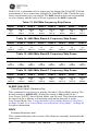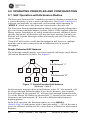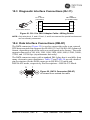
1
Spread Spectrum
Data Transceiver
MDS 05-2708A01, Rev. E
JULY 2009
Installation &
OperationManual
Guide
Reference
MDS TransNET 900™
MDS TransNET 2400™
QUICK START GUIDE
1. Install and connect the antenna system to the transceiver
• Use a high-quality gain antenna, mounted in the clear.
• Use a low-loss feedline such as LMR 400.
• Preset directional antennas in the direction of desired transmission/reception.
2. Connect the data equipment to the radio’s DB-9F DATA connector
• Connect only the required pins. EIA-232, shown below, typically uses only
TXD, RXD and GND. (See Page 71 for EIA-485 interface connections.)
TXD
RXD 3
2
RXD
GND 7
5
GND
RTS 4
CTS 5
DTR 20
DSR 6
JUMPERS:
Only if required by RTU.
See manual for additional details.
DB-9
DB-9
TXD 3
3
TXD
RXD 2
2
RXD
GND 5
5
GND
DTR 4
DSR 6
RTS 7
TRANSCEIVER
(DCE)
DB-9
3
DATA EQUIPMENT
(DTE)
DATA EQUIPMENT
(DTE)
DB-25
TXD 2
TRANSCEIVER
(DCE)
• Verify the connected data equipment is configured as DTE. The radio is DCE.
JUMPERS:
Only if required by RTU.
See manual for additional details.
CTS 8
3. Apply DC power to the radio. Use the supplied 2-pin connector
• Input voltage is 6–30 Vdc. Observe proper polarity. The left pin is positive (+)
and the right pin is negative (–). (See Page 17 for details.)
4. Configure with a PC terminal or TransNET Configuration Software
• Connect computer to radio’s DIAG connector. See Page 69 for cable wiring.
• Set the Mode using the MODE M (Master), MODE R (Remote), or MODE X
(Extension) command. (Note: Only one Master is permitted in a system.)
• Set a unique Network Address (1–65000) using ADDR command. Each radio
in the system must have the same network address. Tip: Use the last four
digits of the Master’s serial number to help avoid conflicts with other users.
• Set the baud rate/data interface parameters. Default setting is 9600 bps, 8
data bits, no parity, 1 stop bit. If changes are required, use the BAUD xxxxx
abc command where xxxxx equals the data rate (300–115200 bps) and abc
equals the communication parameters as follows:
a = Data Bits (7 or 8)
b = Parity (N for None, O for Odd, E for Even
c = Stop Bits (1 or 2)
NOTE: 7N1, 8E2 and 8O2 are not supported.
5. Verify proper operation by observing the LED display
• Refer to Table 6 on Page 20 for a description of the status LEDs.
• Refine directional antenna headings for maximum received signal strength
using the RSSI command. (Remotes must be synchronized with the master.)
CONTENTS
1.0 ABOUT THIS MANUAL .........................................................1
2.0 PRODUCT DESCRIPTION....................................................1
2.1
2.2
2.3
2.4
Transceiver Features ......................................................1
Model Number Codes .....................................................2
Spread Spectrum Radios—How Are They Different? .....2
Typical Applications ........................................................2
Multiple Address Systems (MAS) ....................................2
Point-to-Point System ......................................................3
Adding a Tail-End Link to an Existing Network ................3
Extending a TransNET Network with a Repeater ............4
2.5 Accessories .....................................................................5
3.0 INSTALLATION PLANNING...................................................6
3.1 General Requirements ....................................................6
3.2 Site Selection ..................................................................6
Terrain and Signal Strength .............................................7
Conducting a Site Survey ................................................7
3.3 A Word About Radio Interference ...................................8
3.4 Antenna & Feedline Selection .........................................9
Antennas..........................................................................9
Feedlines .........................................................................10
Antenna System Ground .................................................11
3.5 How Much Output Power Can be Used? ........................12
4.0 INSTALLATION ......................................................................14
4.1
4.2
4.3
4.4
Transceiver Installation ...................................................14
Configuring Multiple Remote Units .................................18
Tail-End Links ..................................................................18
Configuring a Network for Extensions .............................19
5.0 OPERATION ..........................................................................19
5.1 Initial Start-up ..................................................................19
MDS 05-2708A01, Rev. E
MDS TransNET Ref. Manual
i
5.2 Performance Optimization .............................................. 20
Antenna Aiming ............................................................... 20
Antenna SWR Check ...................................................... 20
Data Buffer Setting—Modbus Protocol ........................... 21
Hoptime Setting............................................................... 21
TotalFlow™ Protocol at 9600 with Sleep Mode............... 21
Operation at 115200 bps ................................................. 21
Baud Rate Setting ........................................................... 21
Radio Interference Checks.............................................. 22
6.0 RADIO PROGRAMMING ...................................................... 22
6.1 Radio Programming Methods ......................................... 22
Terminal Interface............................................................ 22
PC-Based Configuration Tool .......................................... 22
6.2 User Commands ............................................................ 23
Entering Commands ....................................................... 23
6.3 Detailed Command Descriptions .................................... 28
ADDR [1–65000] ............................................................. 29
Network Address
AMASK [0000 0000–FFFF FFFF] ................................... 29
Alarm Mask
AT [ON, OFF] .................................................................. 29
Hayes-Compatible AT Command Support
ASENSE [HI/LO] ............................................................. 29
Alarm Output Sense
BAUD [xxxxx abc] ........................................................... 29
Data Interface Port Baud Rate
BAND [A, B, C] ................................................................ 30
Select Sub-Band (Normally used for 2.4 GHz model)
BUFF [ON, OFF] ............................................................. 30
Data Buffer Mode
CODE [NONE, 1…255] ................................................... 31
Security Code
CSADDR [1–65000, NONE]............................................ 31
Clock-Synchronizing Master Address
CTS [0–255] .................................................................... 31
Clear-to-Send Delay
ii
MDS TransNET Ref. Manual
MDS 05-2708A01, Rev. E
CTSHOLD [0–60000].......................................................32
Clear-to-Send Hold Time
DEVICE [DCE, CTS KEY] ..............................................32
Radio-MODEM Behavior
DLINK [xxxxx/ON/OFF]....................................................32
InSite Diagnostics Link Support
DKEY ...............................................................................33
Turn Off Radio Transmitter ‘s Test Signal
DTYPE [NODE/ROOT] ....................................................33
Network Diagnostics Mode
FEC [ON, OFF] ................................................................33
Forward Error Correction
HOPTIME [7, 14, 28] .......................................................34
Radio Transmitter Hop Timing
INIT ..................................................................................34
Initialize; Restore to Factory Defaults
HREV...............................................................................35
Hardware Revision
KEY..................................................................................35
Turn On Radio Transmitter Test Signal
LED [ON, OFF] ................................................................36
Enable/Disable PCB LEDs
LPM [1, 0] ........................................................................36
Low-Power Mode—Masters Only
LPMHOLD [0–1000] ........................................................36
Low-Power Mode Sleep Time
MODE [M, R, X] ...............................................................36
Radio Operating Mode
MRSSI [NONE, –40...–90] ...............................................37
Minimum RSSI for Mobile Operation
OT [ON, OFF] ..................................................................37
Output Trigger
OWM [xxxxx]....................................................................37
“Owner’s Message”
OWN [xxxxx] ....................................................................37
“Owner’s Name”
MDS 05-2708A01, Rev. E
MDS TransNET Ref. Manual
iii
PORT [RS232, RS485] ................................................... 37
Data Interface Port Signaling Standard
PWR [20–30]................................................................... 38
Radio Transmitter Power Level
REPEAT [0–10] ............................................................... 38
Downstream Repeat Transmission Count
RETRY [0–10] ................................................................. 38
Upstream Repeat Transmission Count
RSSI................................................................................ 38
Received Signal Strength Indicator
RTU [ON, OFF, 0-80]....................................................... 39
Remote Terminal Unit Simulator
RX [xxxx] ......................................................................... 39
Radio Receive Test Frequency
RXD [0–235] / [ON/OFF] ................................................. 39
RXD Delay
RXTOT [NONE, 0–1440]................................................. 40
Receive Data Timeout-Timer
SAF [ON, OFF]................................................................ 40
Store-and-Forward Services Support
SETUP ............................................................................ 40
Setup Radio Test
SER ................................................................................. 40
Radio Serial Number
SHOW CON .................................................................... 41
Show Virtual Connection Status
SHOW PWR.................................................................... 41
Show Measured RF Transmit Power
SHOW SYNC .................................................................. 41
Show Clock-Synchronization Master Network Address
SKIP [NONE, 1...8].......................................................... 41
Skip Radio Operating Zones
SLEEP [ON, OFF] ........................................................... 42
Transceiver Sleep—Remotes Only
SREV .............................................................................. 42
Firmware Revision Level
iv
MDS TransNET Ref. Manual
MDS 05-2708A01, Rev. E
STAT ................................................................................43
Alarm Status
TEMP...............................................................................43
Radio’s Internal Temperature
TX [xxxx] ..........................................................................43
Radio Transmit Test Frequency
UNIT [10000–65000] .......................................................43
Unit Address
XADDR [0–31] .................................................................44
Extended Address
XMAP [00000000-FFFFFFFF].........................................44
Map of Extension Addresses
XPRI [0–31] .....................................................................44
Primary Extended Address
XRSSI [NONE, –40...–120]..............................................44
Extension RSSI Level
ZONE CLEAR..................................................................44
Clear Zone Statistics Log
ZONE DATA.....................................................................44
Read Zone Statistics Log
7.0 TROUBLESHOOTING ...........................................................45
7.1 LED Indicators ................................................................46
7.2 Alarm Codes ...................................................................46
Checking for Alarms—STAT command ...........................46
Major Alarms versus Minor Alarms..................................46
Alarm Code Definitions ....................................................47
7.3 Troubleshooting Chart ....................................................48
7.4 Performing Network-Wide Remote Diagnostics ..............49
7.5 Internal Fuse Replacement .............................................50
8.0 RADIO FIRMWARE UPGRADES ..........................................51
8.1 Obtaining New Firmware ................................................51
Saving a Web-Site Firmware File Onto Your PC .............51
8.2 Installing Firmware Into Your Radio ................................51
9.0 OPERATING PRINCIPLES AND CONFIGURATION ............52
MDS 05-2708A01, Rev. E
MDS TransNET Ref. Manual
v
9.1 SAF Operation with Extension Radios ........................... 52
Simple Extended SAF Network ....................................... 52
Extended SAF Network ................................................... 53
Retransmission and ARQ Operation ............................... 53
SAF Configuration Example ............................................ 53
9.2 Synchronizing Network Units .......................................... 54
Synchronization Messages ............................................. 55
9.3 Using AT Commands ...................................................... 55
9.4 Configuration Parameters for
Store-and-Forward Services ........................................ 57
9.5 Using the Radio’s Sleep Mode (Remote Units Only) ...... 59
Sleep Mode Example ...................................................... 60
9.6 Low-Power Mode (LPM)—Master Enabled .................... 60
Setup Commands ........................................................... 60
Reading RSSI and Other Parameters
with LPM Enabled .................................................... 61
Power Consumption Influence by
HOPTIME and SAF Settings .................................... 61
9.7 Low-Power Mode versus Remote’s Sleep Mode ............ 62
9.8 Mobile Operation Support .............................................. 62
Introduction ..................................................................... 62
Operational Influences—Hoptime & SAF ........................ 63
9.9 MIRRORED BITS™ Protocol Support ........................... 63
9.10 Seamless Mode Emulation .......................................... 63
9.11 Full-Duplex Emulation ................................................... 63
9.12 Co-Located and Close-Proximity Masters .................... 63
Master Station Configuration ......................................... 64
Antenna System for Co-Located Master Stations ......... 64
9.13 Security ........................................................................ 65
10.0
TECHNICAL REFERENCE ................................................ 66
10.1
10.2
10.3
10.4
Product Specifications—900 MHz ................................ 66
Product Specifications—2.4 GHz ................................. 67
Diagnostic Interface Connections (RJ-11) .................... 69
Data Interface Connections (DB-9F) ............................ 69
Pin Descriptions—RS/EIA-232 Mode............................ 70
Pin Descriptions—RS/EIA-422/485 Mode..................... 71
10.5 User Configurable I/O Connections .............................. 72
Using the I/O Points with InSite™ NMS Software ......... 73
vi
MDS TransNET Ref. Manual
MDS 05-2708A01, Rev. E
Application Example—Digital Input and
Output at a Remote .........................................................73
10.6 dBm-Watts-Volts Conversion Chart ..............................74
Copyright Notice
This Installation and Operation Guide and all software described herein are Copyright 2009 by
GE MDS, LLC. All rights reserved. Microwave Data Systems Inc. reserves its right to correct
any errors and omissions in this manual.
MDS Quality Policy Statement
We, the employees of Microwave Data Systems, are committed to understanding and exceeding
our customer’s needs and expectations.
• We appreciate our customers’ patronage. They are our business.
• We promise to serve them and anticipate their needs.
• We are committed to providing solutions that are cost effective, innovative and reliable,
with consistently high levels of quality.
We are committed to the continuous improvement of all of our systems and processes, to improve
product quality and increase customer satisfaction.
RF Exposure Notice
RF EXPOSURE
Professional installation required. The radio equipment described in this guide
emits radio frequency energy. Although the power level is low, the concentrated
energy from a directional antenna may pose a health hazard. Do not allow people
to come closer than 23 cm (9 inches) to the antenna when the transmitter is operating in indoor or outdoor environments in the 900 MHz band or 11.2 cm (4.4
inches) in the 2400 MHz band. More information on RF exposure is available on
the Internet at www.fcc.gov/oet/info/documents/bulletins.
ISO 9001 Registration
Microwave Data Systems adheres to the internationally-accepted ISO 9001 quality system standard.
UL/CSA Notice
The MDS TransNET 900 is available for use in Class I, Division 2, Groups A, B, C & D Hazardous Locations. Such locations are defined in Article 500 of the National Fire Protection Association (NFPA) publication NFPA 70, otherwise known as the National Electrical Code.
(Approval of the MDS TransNET 2400 is pending as of August 2006.)
The transceiver has been recognized for use in these hazardous locations by two independent
agencies —Underwriters Laboratories (UL) and the Canadian Standards Association (CSA). The
UL certification for the transceiver is as a Recognized Component for use in these hazardous
locations, in accordance with UL Standard 1604, UL508. The CSA Certification is in accordance
with CSA STD C22.2 No. 213-M1987.
UL/CSA Conditions of Approval: The transceiver is not acceptable as a stand-alone unit for use
in the hazardous locations described above. It must either be mounted within another piece of
equipment which is certified for hazardous locations, or installed within guidelines, or conditions
of approval, as set forth by the approving agencies. These conditions of approval are as follows:
1. The transceiver must be mounted within a separate enclosure which is suitable for the
intended application.
2. The coaxial antenna cable, power input cable and interface cables must be routed through
conduit in accordance with Division 2 wiring methods as specified in the National Electrical
Code, Article 501.4(B).
3. The transceiver must be used within its Recognized “Ratings”.
MDS 05-2708A01, Rev. E
MDS TransNET Ref. Manual
vii
4. Installation, operation and maintenance of the transceiver should be in accordance with the
transceiver's installation manual, and the National Electrical Code.
5. Tampering or replacement with non-factory components may adversely affect the safe use of
the transceiver in hazardous locations, and may void the approval.
6. A power connector with screw-type retaining screws as supplied by MDS must be used.
When installed in a Class I, Div. 2, Groups A, B, C or D hazardous location, observe the following: WARNING —EXPLOSION HAZARD Do not disconnect equipment unless power
has been switched off or the area is know to be non-hazardous.
Refer to Articles 500 through 502 of the National Electrical Code (NFPA 70) for further information on hazardous locations and approved Division 2 wiring methods.
FCC Part 15 Approval Notice
The MDS TransNET 900™ (FCC ID: E5MDS-EL805) and MDS TransNET 2400™ transceivers (Pending FCC ID: E5MDS-EL805-24) comply with Part 15 of the FCC Rules. Operation
is subject to the following two conditions: (1) this device may not cause harmful interference,
and (2) this device must accept any interference received, including interference that may cause
undesired operation. This device is specifically designed to be used under Section 15.247 of the
FCC Rules and Regulations. Any unauthorized modification or changes to this device without
the express approval of Microwave Data Systems may void the user’s authority to operate this
device. Furthermore, this device is intended to be used only when installed in accordance with
the instructions outlined in this manual. Failure to comply with these instructions may also void
the user’s authority to operate this device.
Manual Revision and Accuracy
While every reasonable effort has been made to ensure the accuracy of this manual, product
improvements may result in minor differences between the manual and the product shipped to
you. If you have additional questions or need an exact specification for a product, please contact
our Customer Service Team using the information at the back of this guide. In addition, manual
updates can often be found on the MDS Web site at www.microwavedata.com.
ESD Notice
To prevent malfunction or damage to this radio, which may be caused by Electrostatic Discharge (ESD), the radio should be properly grounded by connection to the
ground stud on the rear panel. In addition, the installer or operator should follow
proper ESD precautions, such as touching a grounded bare metal object to dissipate
body charge, prior to adjusting front panel controls or connecting or disconnecting
cables on the front or rear panels.
Environmental Information
The equipment that you purchased has required the extraction and use of natural
resources for its production. Improper disposal may contaminate the environment and
present a health risk due to hazardous substances contained within. To avoid dissemination of these substances into our environment, and to diminish the demand on natural resources, we encourage you to use the appropriate recycling systems for disposal. These
systems will reuse or recycle most of the materials found in this equipment in a sound way. Please
contact MDS or your supplier for more information on the proper disposal of this equipment.
Product Test Data Sheets
Test Data Sheets showing the original factory test results for this unit are available upon request
from the GE MDS Quality Leader. Contact the factory using the information at the back of this
manual. Serial numbers must be provided for each product where a Test Data Sheet is required.
viii
MDS TransNET Ref. Manual
MDS 05-2708A01, Rev. E
1.0 ABOUT THIS MANUAL
This manual presents installation and operating instructions of the
MDS TransNET 900™ and MDS TransNET 2400™ transceivers for use by
a professional installer. This person is expected to install, operate, and
perform basic system maintenance on the described radio. Following installation, we suggest keeping this manual near the equipment for future reference.
2.0 PRODUCT DESCRIPTION
The transceiver, shown in Figure 1, is a spread spectrum radio designed for
license-free operation. These units employ Digital Signal Processing (DSP)
technology to provide highly-reliable long-distance communications, even in
the presence of weak signals or interference.
DSP technology also makes it possible to obtain information about radio
operation and troubleshoot problems, without going to the Remote radio site.
Using appropriate software at the Master station, diagnostic data can be
obtained on any DSP radio in the system, even while payload data is being
transmitted. (See “Performing Network-Wide Remote Diagnostics” on
Page 49.)
The transceiver is housed in a compact and rugged die-cast enclosure that
need only be protected from direct exposure to the weather. It contains a
single printed circuit board with all necessary components for radio operation. No jumper settings or manual adjustments are required to configure the
radio for operation.
Figure 1.
MDS TransNET
Series Transceiver
2.1 Transceiver Features
Listed below are several key features of the transceiver. These are designed
to ease the installation and configuration of the radio, while retaining the
ability to make changes in the future.
• 902–928 MHz operation using the TransNET 900
• 2400–2482 MHz ISM band operation with the TransNET 2400
• User-selectable option to skip sub-bands with constant interference
MDS 05-2708A01, Rev. E
MDS TransNET Ref. Manual
1
• 65,000 available network addresses
• Network-wide configuration from the Master station eliminates most
trips to Remote sites
• Data transparency ensures compatibility with virtually all asynchronous
SCADA system RTUs
• Peak-hold RSSI averaged over eight hop cycles
• Operation at up to 115,200 bps continuous data flow
• Store-and-Forward repeater operation
• Data latency typically less than 10 ms
• Same hardware for Master or Remote configuration
• Supports RS/EIA-232 and RS/EIA-485 user interface
• Low current consumption; typically less than 3 mA in “sleep” mode
NOTE: Some radio features may not be available on all models, or limited by the options purchased, or the applicable regulatory constraints for the region in which
the radio will operate.
2.2 Model Number Codes
The radio model number is printed on the label on the end of the radio’s enclosure. It provides key information about how the radio was configured when it
was shipped from the factory. This number is subject to many variations
depending on what options are installed and where (country) the product is
used. Contact MDS is you have questions on the meaning of the code.
2.3 Spread Spectrum Radios—
How Are They Different?
The main difference between a traditional (licensed) radio and the
MDS TransNET transceiver is that this unit “hops” from channel to channel
many times per second using a specific hop pattern applied to all radios in the
network. A distinct hopping pattern is provided for each of the 65,000 available network addresses, thereby minimizing the chance of interference with
other spread spectrum systems. In the USA, and some other countries, no
license is required to install and operate this type of radio system, provided
that RF power and antenna gain restrictions are observed.
2.4 Typical Applications
Multiple Address Systems (MAS)
This is the most common application of the transceiver. It consists of a central
control station (Master) and two or more associated Remote units, as shown
in Figure 2. An MAS network provides communications between a central
host computer and remote terminal units (RTUs) or other data collection
2
MDS TransNET Ref. Manual
MDS 05-2708A01, Rev. E
devices. The operation of the radio system is transparent to the computer
equipment. When used in this application, the transceiver provides an excellent alternative to traditional (licensed) MAS radio systems.
Invisibleplaceholder
MDS TransNET
Remote
RTU
RXD
RTU
MDS TransNET
Remote
TXD
C
SYN
PWR
RXD
TXD
C
SYN
PWR
MDS TransNET
Remote
RXD
TXD
C
SYN
RTU
PWR
MDS TransNET
Master
RXD
RXD
TXD
TXD
C
SYN
C
SYN
PWR
RTU
PWR
MDS TransNET
Remote
Host System
Figure 2. Typical MAS Network
Point-to-Point System
A point-to-point configuration (Figure 3) is a simple arrangement consisting
of just two radios—a Master and a Remote. This provides a half-duplex
communications link for the transfer of data between two locations.
Invisibleplaceholder
MDS TransNET
Master
MDS TransNET
Remote
Host System
Figure 3. Typical Point-to-Point Link
Adding a Tail-End Link to an Existing Network
A tail-end link can be used to extend the range of a traditional (licensed) MAS
system. This might be required if an outlying site is blocked from the MAS
Master station by a natural or man-made obstruction. In this arrangement, a
MDS 05-2708A01, Rev. E
MDS TransNET Ref. Manual
3
TransNET radio links the outlying Remote site into the rest of a licensed
MAS system by sending data from that site to an associated TransNET
installed at one of the licensed Remote sites (see Figure 4).
As the data from the outlying site is received at the licensed Remote site, it is
transferred to the licensed radio (via a local cable connection) and is then
transmitted to the MAS Master station in the usual manner. Additional details
for tail-end links are given in Section 4.3 (Page 18).
Invisibleplaceholder
REPEATER STATION
MDS x710B
Series Radio
Master Station
MDS TransNET
Master
SP
RE
TO AD
OU SPE
TL CT
YI RU
NG M
SI LIN
TE K
PWR
SYN
C
TXD
RXD
ACTIVE
STBY
ALARM
RX ALR
TX ALR
ACTIVE
LINE
STBY
ALARM
RX ALR
TX ALR
LINE
ENTER
ESCAPE
Null-Modem Cable
MDS TransNET
Remote
Remote
Radio
PWR
Remote
Radio
SYN
C
TXD
RXD
RTU
RTU
RTU
OUTLYING
REMOTE SITE
LICENSE-FREE SPREAD SPECTRUM SYSTEM
MAS SYSTEM (LICENSED OR UNLICENSED)
Figure 4. Typical Tail-End Link Arrangement
Extending a TransNET Network with a Repeater
Similar to a Tail-End Link, Store-and-Forward (SAF) offers a way to physically extend the network range, but in a simple and economical manner. SAF
works by dividing a network into a vertical hierarchy of two or more
sub-networks. Extension radios (designated as MODE X) serve as single-radio
repeaters that link adjacent sub-networks, and move data from one
sub-network to the next one.
Invisibleplaceholder
REPEATER STATION
SP
MDS TransNET
Master
MODE = M
SAF = ON
RE
TO AD
OU SPE
TL CT
YI RU
NG M
SI LIN
TE K
RTU
MDS TransNET
Extension
MODE = X
MDS TransNET
Remote
MODE = R
MDS TransNET
Remote
MODE = R
RTU
MDS TransNET
Remote
MODE = R
RTU
RTU
OUTLYING
REMOTE SITE
Figure 5. TransNET Repeater Network
4
MDS TransNET Ref. Manual
MDS 05-2708A01, Rev. E
2.5 Accessories
The transceiver can be used with one or more of the accessories listed in
Table 1. Contact the factory for ordering details.
Table 1. Accessories
Accessory
Description
MDS Part No.
AC Power
Adapter
Small power supply module designed for continuous service. UL approved.
Input: 120/220 Vac
Output: 12 Vdc @ 500 mA (20 Watts)
01-3682A02
2-Pin DC Power
Plug
Mates with power connector on the transceiver.
Screw terminals are provided for wires.
73-1194A39
Fuse (Internal)
Fuse, 2A SMF Slo-Blo
29-1784A03
Omnidirectional
Antennas
Rugged antennas suited for use at Master
stations. Consult MDS for details.
Various;
Consult factory
900 MHz
Yagi Antennas
Rugged directional antennas suited for use at
Remote stations. Consult MDS for details.
Various;
Consult factory
2400 MHz
Antennas
Rugged directional antennas suited for use at
Remote stations.
Various;
Consult factory
900 MHz
Bandpass Filter
Antenna system filter to aid in eliminating interference from paging system transmissions.
20-2822A02
TNC-to-N
Adapter Cable
(3 ft./1 meter)
Coaxial cable used to connect the radio’s TNC
antenna connector to a Type-N style commonly
used on large-diameter coaxial cables.
97-1677A159
TNC-to-N
Adapter Cable
(6 ft./1.8 meter)
Coaxial cable used to connect the radio’s TNC
antenna connector to a Type-N style commonly
used on large-diameter coaxial cables.
97-1677A160
TNC-to-N RF
Adaptor Plug
Adapts radio’s antenna connector to Type-N
style commonly used on large-diameter coaxial
cables.
97-1677A161
RS/EIA-232
Cable
Shielded data cable fitted with DB-9 male and
DB-9 female, 6 ft./1.8 meter.
97-1971A03
RJ-11 to DB-9
Adapter Cable
For connecting a PC terminal to the transceiver
via the radio’s DIAG(nostics) connector. Used
for programming and diagnostics.
03-3246A01
Flat-Surface
Mounting
Brackets
Brackets: 2˝ x 3˝ plates designed to be screwed
onto the bottom of the transceiver for surface-mounting the radio.
82-1753-A01
Mounting
Bracket Screws
Screws: 6-32/1/4˝ with locking adhesive.
(Industry Standard MS 51957-26)
70-2620-A01
19-Inch Rail
Mounting
Brackets
Adaptor for mounting the radio in a standard
19-inch equipment rack.
Consult Factory
DIN Rail Mtg.
Brackets
Adaptor for mounting the radio in a standard
19-inch equipment rack.
03-4022A01
MDS 05-2708A01, Rev. E
MDS TransNET Ref. Manual
5
3.0 INSTALLATION PLANNING
The installation of the radio is not difficult, but it does require some planning
to ensure station reliability and efficiency. This section provides tips for
selecting an appropriate site, choosing an antenna system, and reducing the
chance of harmful interference.
3.1 General Requirements
There are three main requirements for installing the radio—adequate and
stable primary power, a good antenna system, and the compatible interface
between the transceiver and the data device.
Figure 6 shows a typical Remote station arrangement. Master stations are
similar, but an omni-directional antenna is normally used instead of a directional type, and a host computer replaces the data terminal equipment.
Invisibleplaceholder
DATA TERMINAL
EQUIPMENT
ANTENNA
SYSTEM
MDS Transceiver
E
N
LI
ED
SS
FE
O
POWER SUPPLY
13.8 VDC @ 500 mA
(6–30 Vdc)
-L
W
LO
Figure 6. Typical Remote Station Arrangement
3.2 Site Selection
For a successful installation, careful thought must be given to selecting proper
sites for the Master and Remote stations. Suitable sites should provide the
following:
• Protection from direct weather exposure
• A source of adequate and stable primary power
• Suitable entrances for antenna, interface or other required cabling
• Antenna location that provides an unobstructed transmission path in the
direction of the associated station(s)
6
MDS TransNET Ref. Manual
MDS 05-2708A01, Rev. E
These requirements can be quickly determined in most cases. A possible
exception is the last item—verifying that an unobstructed transmission path
exists. Radio signals travel primarily by line-of-sight, and obstructions
between the sending and receiving stations will affect system performance. If
you are not familiar with the effects of terrain and other obstructions on radio
transmission, the discussion below will provide helpful background.
Terrain and Signal Strength
While the 900 and 2400 MHz bands offer many advantages over VHF and
lower UHF frequencies for data transmission, they are more prone to signal
attenuation from obstructions such as terrain, foliage or buildings in the transmission path.
A line-of-sight transmission path between the Master station and its associated Remote site(s) is highly desirable and provides the most reliable communications link. A line-of-sight path can often be achieved by mounting the
station antenna on a tower or other elevated structure that raises it to a level
sufficient to clear surrounding terrain and other obstructions.
The importance of a clear transmission path relates closely to the distance to
be covered by the system. If the system is to cover only a limited geographic
area, say up to 3 miles (4.8 km), then some obstructions in the communications path can usually be tolerated with minimal impact. For longer range
systems, any substantial obstruction in the communications path could
compromise the performance of the system, or block communications
entirely.
Much depends on the minimum signal strength that can be tolerated in a given
system. Fade margin for a TransNET system does not usually have to be as
conservative as a licensed system. The nature of TransNET’s
frequency-hopping algorithm reduces the impact of frequency-selective
fading.
Although the exact figure will differ from one system to another, a Received
Signal Strength Indication (RSSI) of –100 dBm will often provide acceptable
performance. A higher signal strength is generally desirable and may be
needed in special cases—for example, urban deployment.
Conducting a Site Survey
If you are in doubt about the suitability of the radio sites in your system, it is
best to evaluate them before a permanent installation is begun. This can be
done with an on-the-air test (preferred method), or indirectly, using
path-study software.
An on-the-air test is preferred because it allows you to see firsthand the
factors involved at an installation site and to directly observe the quality of
system operation. Even if a computer path study was conducted earlier, this
test should be done to verify the predicted results.
The test can be performed by first installing a radio and antenna at the
proposed Master station site and then visiting each Remote site with a transceiver and a hand-held antenna.
MDS 05-2708A01, Rev. E
MDS TransNET Ref. Manual
7
With the hand-held antenna positioned near the proposed mounting spot, a
technician can check for synchronization with the Master station (shown by
a lit SYNC lamp on the front panel) and measure the reported RSSI value. If
adequate signal strength cannot be obtained, it may be necessary to mount the
station antennas higher, use higher gain antennas, or select a different site. To
prepare the equipment for an on-the-air test, follow the general installation
procedures given in this guide and become familiar with the operating
instructions given in Section 5.0, beginning on Page 19.
If time is short, and a site survey is impractical, a computer path study is a
good alternative. Factors such as terrain, distance, transmitter power, receiver
sensitivity, and other conditions are taken into account to predict the performance of a proposed system. Contact MDS’ Technical Services Group for
more information on path study services.
3.3 A Word About Radio Interference
The radio shares the frequency spectrum with other services and other Part 15
(unlicensed) devices in the USA. As such, near 100% error free communications may not be achieved in a given location, and some level of interference
should be expected. However, the radio’s flexible design and hopping techniques should allow adequate performance as long as care is taken in
choosing station location, configuration of radio parameters and software/protocol techniques.
In general, keep the following points in mind when setting up your communications network:
1. Systems installed in rural areas are least likely to encounter interference;
those in suburban and urban environments are more likely to be affected
by other devices operating in the license-free frequency band and by
adjacent licensed services.
2. If possible, use a directional antenna at Remote sites. Although these
antennas may be more costly than omnidirectional types, they confine the
transmission and reception pattern to a comparatively narrow lobe, which
minimizes interference to (and from) stations located outside the pattern.
3. If interference is suspected from a nearby licensed system (such as a
paging transmitter), it may be helpful to use horizontal polarization of all
antennas in the network. Because most other services use vertical
polarization in these bands, an additional 20 dB of attenuation to
interference can be achieved by using horizontal polarization.
4. Multiple transceiver systems can co-exist in proximity to each other with
only very minor interference as long as they are each assigned a unique
network address. Each network address has a different hop pattern.
Additional RF isolation can be achieved by using separate directional
antennas with as much vertical or horizontal separation as is practical.
Vertical separation of antennas is more effective per foot/meter than
horizontal.
8
MDS TransNET Ref. Manual
MDS 05-2708A01, Rev. E
5. If constant interference is present in a particular frequency zone, it may
be necessary to “lock out” that zone from the radio’s hopping pattern.
The radio includes built-in tools to help users remove blocked frequency
zones. Refer to the discussion of the SKIP command (Page 41) for more
information. In the USA, a maximum of four zones may be skipped, per
FCC rules. Check the regulatory requirements for your region.
6. Interference can also come from out-of-band RF sources such as paging
systems. Installation of a bandpass filter in the antenna system may bring
relief. (Contact the MDS Customer Service Department for
recommendations and sources of suitable filters.)
7. Proper use of the RETRY and REPEAT commands may be helpful in areas
with heavy interference.
The RETRY command sets the maximum number of times (0 to 10) that a
radio will re-transmit upstream data over the air. Values greater than 0
successively improve the chances of a message getting through when
interference is a problem.
The REPEAT command sets a fixed number of unconditional
retransmissions for downstream data.
8. The RF power output of all radios in a system should be set for the lowest
level necessary for reliable communications. This lessens the chance of
causing unnecessary interference to nearby systems.
3.4 Antenna & Feedline Selection
Antennas
The equipment can be used with a number of antennas. The exact style used
depends on the physical size and layout of a system. Contact your MDS representative for specific recommendations on antenna types and hardware
sources.
In general, an omnidirectional antenna (Figure 7 and Figure 8) is used at the
Master station site in an MAS system. This provides equal coverage to all of
the Remote sites.
NOTE: Antenna polarization is important. If the wrong polarization is used, a signal reduction of 20 dB or more will result. Most systems using a gain-type omnidirectional antenna at the Master station employ vertical polarization of the signal;
therefore, the Remote antenna(s) must also be vertically polarized (elements
oriented perpendicular to the horizon).
When required, horizontally polarized omnidirectional antennas are also available. Contact your MDS representative for details.
MDS 05-2708A01, Rev. E
MDS TransNET Ref. Manual
9
Figure 7.
Omnidirectional Antenna
(mounted to mast)
At Remote sites and point-to-point systems, a directional Yagi antenna
(Figure 8), is generally recommended to minimize interference to and from
other users. Antennas are available from a sources including MDS.
Invisibleplaceholder
Figure 8. Typical Yagi Antenna
mounted to a mast
Feedlines
The choice of feedline used with the antenna should be carefully considered.
Poor-quality coaxial cables should be avoided, as they will degrade system
performance for both transmission and reception. The cable should be kept as
short as possible to minimize signal loss.
For cable runs of less than 20 feet (6 meters), or for short range transmission,
an inexpensive type such as Type RG-8A/U may be acceptable. Otherwise,
we recommend using a low-loss cable type suited for 900 MHz, such as
Times Microwave LMR 400® or Andrew Heliax®.
10
MDS TransNET Ref. Manual
MDS 05-2708A01, Rev. E
Table 2 lists several types of feedlines and indicates the signal losses (in dB)
that result when using various lengths of each cable at 900 MHz and Table 3
for 2.4 GHz. The choice of cable will depend on the required length, cost
considerations, and the amount of signal loss that can be tolerated.
Table 2. Length vs. loss in coaxial cables at 900 MHz
10 Feet
(3.05 Meters)
50 Feet
(15.24 Meters)
100 Feet
(30.48 Meters)
300 Feet
(91.44 Meters)
LMR 400
0.39 dB
1.95 dB
3.9 dB
Unacceptable
Loss
1/2 inch
HELIAX
0.23 dB
1.15 dB
2.29 dB
6.87 dB
7/8 inch
HELIAX
0.13 dB
0.64 dB
1.28 dB
3.84 dB
1-1/4 inch
HELIAX
0.10 dB
0.48 dB
0.95 dB
2.85 dB
1-5/8 inch
HELIAX
0.08 dB
0.40 dB
0.80 dB
2.4 dB
Cable Type
Table 3. Length vs. loss in coaxial cables at 2400 MHz
Cable Type
10 Feet
(3.05 Meters)
50 Feet
(15.24 Meters)
100 Feet
(30.48 Meters)
300 Feet
(91.44 Meters)
LMR-400
0.70 dB
3.50 dB
6.61 dB
Unacceptable
Loss
1/2 inch
HELIAX
0.35 dB
1.73 dB
3.46 dB
17.3 dB
7/8 inch
HELIAX
0.20 dB
0.99 dB
1.97 dB
9.85 dB
1-1/4 inch
HELIAX
0.15 dB
0.73 dB
1.45 dB
7.50 dB
Antenna System Ground
Precautions should be taken to assure the antenna and its support structure are
bonded to a good earth ground system to minimize the impact of voltages
created by lightning and atmospheric charges.
CAUTION: Safety grounding systems are beyond the scope of this manual. Below you
will find some elementary advice. These are generalities; every location and
installation is unique and requires a unique safety grounding system design.
Please consider consulting a radio system engineer or other professional for
advice or ground system design. A well-designed ground system will minimize risk of electrical shock to personnel and the chances of equipment
damage.
MDS 05-2708A01, Rev. E
MDS TransNET Ref. Manual
11
Antenna Selection—Choose an antenna that offers a “DC ground” or direct
low-impedance ground connection for all metallic components. This will
allow static charges on the antenna system to be safely dissipated to ground.
It will also provide a low-impedance discharge path to an earth/safety ground
in the event of a direct lightning strike.
Support Earth/Safety Ground—The structure that supports your antenna
system should have a large-gauge ground wire that goes as directly as
possible to an safety/earth ground system. If a tower is used, it should have
its own ground system. Support structure grounds can be bonded to the electrical system ground for increased protection. Do not use the building’s
AC-power supply ground as a safety ground for lightning protection.
Chassis Ground—Connect a safety/earth ground to the ground post
provided on the electronic/electrical equipment. If a ground terminal is
present, bond the chassis to the safety ground at a point that is as close as
possible to the antenna system and primary power entry points on the chassis.
3.5 How Much Output Power Can be Used?
The transceiver is normally supplied from the factory set for an RF power of
+30 dBm (1 Watt) for 900 MHz and +27 dBm (0.5 Watt) for 2400 MHz; this
is the maximum transmitter output power allowed under FCC rules. The
power must be decreased from this level if the antenna system gain exceeds
6 dBi. The allowable level is dependent on the antenna gain, feedline loss, and
the transmitter output power setting. Power considerations for the transceiver
are discussed below.
NOTE: In some countries, the maximum allowable RF output may be limited to less
than your model’s peak output. Be sure to check for and comply with the requirements for your region.
To determine the maximum allowable power setting of the radio, perform the
following steps:
1. Determine the antenna system gain by subtracting the feedline loss (in
dB) from the antenna gain (in dBi). For example, if the antenna gain is
9.5 dBi, and the feedline loss is 1.5 dB, the antenna system gain would be
8 dB. (If the antenna system gain is 6 dB or less, no power adjustment is
required.)
2. Subtract the antenna system gain from 36 dBm (the maximum allowable
EIRP). The result indicates the maximum transmitter power (in dBm)
allowed under the rules. In the example above, this is 28 dBm.
3. If the maximum transmitter power allowed in your region is less than 30
dBm, use the PWR command (described on Page 38) to set the power
accordingly.
12
MDS TransNET Ref. Manual
MDS 05-2708A01, Rev. E
For convenience, Table 4 lists several antenna system gains and shows the
maximum allowable power setting of the radio. Note that a gain of 6 dB or
less entitles you to operate the radio at full power output—30 dBm (1 watt).
Table 4. Antenna system gain vs. power output setting (USA)
for 900 MHz models to achieve +36 dBm EIRP
Antenna System Gain
Maximum Power
Setting
EIRP
(in dBm)
(in dBm)
6 (or less)
30
36
8
28
36
10
26
36
12
24
36
14
22
36
16
20
36
(Antenna Gain in dBia
minus Feedline Loss in dBb)
a. Most antenna manufacturers rate antenna gain in
dBd in their literature. To convert to dBi, add
2.15 dB.
b. Feedline loss varies by cable type and length. To
determine the loss for common lengths of feedline,
see Table 2 on Page 11.
Table 5. Antenna system gain vs. power output setting (USA)
for 2400 MHz models to achieve +36 dBm EIRP
Antenna System Gain
(Antenna Gain in dBia
minus Feedline Loss in dBb
Maximum Power
Setting
EIRP
(in dBm)
(in dBm)
2 dB
27
29
10 dB
26
36
a. Most antenna manufacturers rate antenna gain in
dBd in their literature. To convert to dBi, add
2.15 dB.
b. Feedline loss varies by cable type and length. To
determine the loss for common lengths of feedline,
see Table 2 on Page 11.
MDS 05-2708A01, Rev. E
MDS TransNET Ref. Manual
13
4.0 INSTALLATION
Figure 9 shows the contents of a typical transceiver shipment. Check the
contents against the packing list secured to the outside of the shipping box.
Accessories and spare parts kits, if any, are wrapped separately. Inspect all
items for signs of damage and save all packing materials for possible re-shipment.
Invisibleplaceholder
MDS
Xxxx
MOUNTING
BRACKETS
INSTALLATION &
OPERATION GUIDE,
AND SOFTWARE
(CD AND/OR MANUAL)
2-PIN
POWER PLUG
SPARE FUSE
Figure 9. Typical Transceiver Shipment
User documentation will be provided as a paper manual and/or as a PDF on
the “MDS TransNET Support Package CD” (P/N 03-2708A01). The CD
includes:
• Installation & Operation Guide in PDF (Also known as Adobe
Acrobat™)
• TransNET Configuration Software
If a paper copy is required but not provided with your shipment, please
contact MDS Customer Support Team.
4.1 Transceiver Installation
The following is an overview of a typical procedure for installing the transceiver. In most cases, these steps alone will be sufficient to complete the
installation. Should further information be required, contact the factory using
the information given on the inside back cover of this manual.
If you are installing a tail-end link system, you should also review Section 4.3
(Page 18) for important details on configuration.
NOTE: It is recommended that the Master station be installed first. In this way, it will be
possible to quickly check the operation of each associated Remote station as it
is placed on the air.
1. Mount the transceiver to a stable surface using the brackets supplied with
the radio. (Fasteners/anchors are not supplied.) Figure 10 shows the
dimensions of the transceiver case and its mounting brackets. If possible,
14
MDS TransNET Ref. Manual
MDS 05-2708A01, Rev. E
choose a mounting location that provides easy access to the connectors
on the end of the radio and an unobstructed view of the LED status
indicators.
Invisibleplaceholder
2.75
(7.0 cm)
6.63
(16.64 cm)
1.62
(4.15 cm)
Figure 10. Transceiver Mounting Dimensions
Figure 11 shows the four connectors on the transceiver and their functions.
Invisibleplaceholder
Antenna
Data
Primary Power
(6–30 Vdc)
Diagnostic (Payload)
(Communications)
Figure 11. Interface Connector Functions
2. Install the antenna and antenna feedline for the station. Antennas should
be mounted in the clear and in accordance with the manufacturer’s
instructions. Additional information on antennas and feedlines is
contained in Section 3.4 on Page 9.
NOTE: It is recommended to mount the antenna be at least 10 feet (>3 meters) from the
radio, RTU, sensors and other components of the system to prevent RFI.
3. Connect the data equipment to the transceiver’s DATA connector. Use
only the required pins for the application.
MDS 05-2708A01, Rev. E
MDS TransNET Ref. Manual
15
Typical RS/EIA-232 applications require the use of Pin 2 (receive
data—RXD and Pin 3 (transmit data—TXD). Some systems may require the
use of Pin 7 (Request-to-send—RTS). Figure 13 shows connection details for
the DATA connector for EIA/RS-232 and EIA/RS-485, respectively.
If hardware flow control is desired, Pin 7 (RTS) and Pin 8 (CTS) may also be
connected. For a more detailed discussion of pin functions, see “Data Interface Connections (DB-9F)” on page 69.
Invisibleplaceholder
Pin Function
5
1
9
6
1.....Data Carrier Detect (DCD)
2.....Receive Data (RXD)
3.....Transmit Data (TXD)
4.....Sleep (GND = Sleep)
5.....Signal Ground (GND)
6.....Alarm Output (+5/-5 Vdc)
7.....Ready-to-Send (RTS)
8.....Clear-to-Send (CTS)
9.....Reserved for Special Uses (Do not connect)
Figure 12. DATA Connector Pin Functions, EIA/RS-232 Mode
As viewed from outside the radio
NOTE: The data cabling between the transceiver and the connected device should be
kept as short as possible. For EIA/RS-232 operation, the maximum recommended cable length is 50 feet/15 meters.
Invisibleplaceholder
Pin Function
5
9
1
6
1.....Not Used (Open)
2.....TXD+/TXA, Non-inverted driver output.
Supplies data to connected device.
3.....RXD+/RXA, Non-inverted receiver input.
Accepts data from the connected device.
4.....Sleep Mode Input (GND = Sleep)
5.....Signal Ground (GND)
6.....Not Used (Open)
7.....RXD–/RXB, Inverting receiver input
8.....TXD–/TXB, Inverting driver output
9.....Not Connected (User configureable via internal jumper)
Figure 13. DATA Connector Pin Functions, EIA/RS-485 Mode
As viewed from outside the radio
4. Measure and install the primary power for the transceiver. It must be
within 6–30 Vdc (including transients) and be capable of providing 7.5
watts over this voltage range. (Typical current draw is 400 mA
@13.8 Vdc; 0.9 A @6 Vdc.) A power connector with screw-terminals is
provided with each unit. Strip the wire leads to 0.25˝/6 mm. Be sure to
observe proper polarity. The left pin is the positive input; the right is
negative. (See Figure 14.)
16
MDS TransNET Ref. Manual
MDS 05-2708A01, Rev. E
CAUTION
POSSIBLE
EQUIPMENT
DAMAGE
The radio must be used only with negative-ground systems. Make sure the polarity of the power source is correct. The unit is protected from reverse polarity by an
internal diode and fuse.
Invisibleplaceholder
Lead
Binding
Screws (2)
Wire Ports (2)
Figure 14. Power Connector
(Polarity: Left +, Right –)
CAUTION
POSSIBLE
EQUIPMENT
DAMAGE
The power connector used with the MDS TransNET
transceiver is similar to that used by other MDS products, such as the MDS 9810 and MDS x710 family. The
connectors are not equal and the use of the other style
connector may provide unreliable connections and a
spark may be created.
Only the power connector, shown in Figure 14 with
screw terminals and two retainer screws should be used
with this unit.
5. Set the radio’s basic configuration with a PC terminal connected to the
DIAG(nostics) connector via an RJ-11 to DB-9 adapter cable, MDS
P/N 03-3246A01. (If necessary, a cable of this type may be constructed
using the information shown in Figure 21 on Page 69.) For more
information on connecting a PC terminal and preparing it for use, refer to
Section 6.1 on Page 22.
The three essential settings for the Transceiver are as follows:
Mode—Master, Remote, or Extension
Network Address—a unique number from 1 to 65000
Data Interface Parameters—bps, data bits, parity, stop bits
a.
Set the Mode using the MODE M (Master), MODE R (Remote), or
MODE X (Extension) command. (Note: There can be only one Master radio in a system.)
If any MODE X radios are used in the network, SAF must be turned
on at the Master station. The MODE X radio must be programmed
with an Extended Address (XADDR). Units that need to hear the
MODE X radio must be programmed with an appropriate XPRI and/or
XMAP value. (See “SAF Operation with Extension Radios” on
Page 52 for more information.)
MDS 05-2708A01, Rev. E
MDS TransNET Ref. Manual
17
b.
Set a unique Network Address (1–65000) using ADDR command.
Each radio in the system must have the same network address. Tip:
Use the last four digits of the Master’s serial number to help avoid
conflicts with other users.
c.
Set the baud rate/data interface parameters. Default setting is 9600
bps, 8 data bits, no parity, 1 stop bit. If changes are required, use the
BAUD xxxxx abc command where xxxxx equals the data speed
(300–115200 bps) and abc equals the communication parameters as
follows:
a = Data bits (7 or 8)
b = Parity (N for None, O for Odd, E for Even
c = Stop bits (1 or 2)
NOTE: 7N1, 8E2 and 8O2 are invalid interface parameters.
4.2 Configuring Multiple Remote Units
In most installations, the Remote radios will be programmed with virtually
the same set of parameters. This process can be streamlined by testing key
pieces of equipment—such as the Master, any Extensions, and a typical
Remote—on a benchtop setup prior to installation. This allows you to test
various configurations in a controlled environment. Once the evaluation
network is working satisfactorily, you can save the configuration of each unit
in a data file on your PC’s hard drive through the use of the MDS TransNET
Configuration Software (included on the support CD shipped with the radio,
MDS part number 03-2708A01).Most often, there are many Remote units
that will need configuring. Using the MDS TransNET Configuration Software, you can save the sample unit’s configuration, then open the configuration file with the program and install it in the next Remote. The software will
prevent you from overwriting unit or mode-unique parameters.
4.3 Tail-End Links
A tail-end link is established by connecting an MDS TransNET Series radio
“back-to-back” with another identical radio such as a licensed MDS x710B
Series transceiver. This can be used to link an outlying Remote site into the
rest of an MAS network. (Figure 4 on Page 4 shows a diagram of a typical
tail-end link system.) The wiring connections between the two radios in a
tail-end link system should be made as shown in Figure 15.
18
MDS TransNET Ref. Manual
MDS 05-2708A01, Rev. E
DCE
DB-9
RXD 3
3
TXD
TXD
2
RXD
2
5 GND
GND 7
RTS
4
If required.
8 CTS
MDS TransNET 900
Remote Transceiver
(DEVICE CTS KEY)
MDS x710B Series
Remote Transceiver
(or device requiring keyline)
DCE
DB-25
Figure 15. Data Interface Cable Wiring for Tail-End Links
Any device on the left that requires a keyline, as in this illustration, will
require the bottom line (CTS to RTS) and the TransNET on the right will need
DEVICE type set to CTS KEY. See DEVICE, on Page 32 for details.
4.4 Configuring a Network for Extensions
The installation and configuration of an Extension transceiver is straightforward with only a few unique parameters that need to be considered and set at
each unit.
In every network there can be only one Master station. It will serve as the sole
gateway to the outside world. The tables in “Configuration Parameters for
Store-and-Forward Services” on Page 57 detail the parameters that need to
be set on each type of radio in the network. For a detailed description of this
network design, see “SAF Operation with Extension Radios” on page 52.
5.0 OPERATION
5.1 Initial Start-up
In-service operation of the transceiver is completely automatic. Once the unit
has been properly installed and configured, operator actions are limited to
observing the LED status indicators for proper operation.
If all parameters are correctly set, start operation of the radio as follows:
1. Apply primary power.
2. Observe the transceiver LED status panel for proper indications. Table 6
provides an explanation of the LED functions.
In a normally operating system, the following indications will be seen
within 16 seconds of start-up:
• PWR lamp lit continuously
• SYNC lamp lit continuously
MDS 05-2708A01, Rev. E
MDS TransNET Ref. Manual
19
• Remote radio(s) transmitting data (TXD) and receiving data (RXD) with
Master station
Table 6. LED indicator descriptions
PWR
SYNC
TXD
RXD
Name
Description
PWR
• Continuous—Power is applied to the radio; no problems detected
• Flashing (5 times-per-second)—Fault indication
See “TROUBLESHOOTING” on Page 45
• Off—Radio is unpowered or in Sleep mode
See also, “LED [ON, OFF]” on Page 36
SYNC
Continuous—Radio is receiving/sending synchronization frames
On within 10 seconds of power-up under normal conditions
TXD
Transmit data activity on the DB-9 DATA interface connector
Payload data to connected device
RXD
Receive data activity on the DB-9 DATA interface connector.
Payload data from the connected device
5.2 Performance Optimization
After the basic operation of the radio has been checked, you may wish to optimize its performance using some of the suggestions given here. The effectiveness of these techniques will vary with the design of your system and the
format of the data being sent.
Complete instructions for using the commands referenced in this manual are
provided in “RADIO PROGRAMMING” on Page 22.
Antenna Aiming
For optimum performance, directional antennas must be accurately aimed in
the direction of desired transmission. The easiest way to do this is to point the
antenna in the approximate direction, then use the Remote radio’s RSSI
command (Received Signal Strength Indicator) to further refine the heading
for maximum received signal strength.
In an MAS system, RSSI readings are only meaningful when initiated from a
Remote station. This is because the Master station typically receives signals
from several Remote sites, and the RSSI would be continually changing as the
Master receives from each Remote in turn. Adjust the antenna for the highest
(most positive) value to insure the greatest communication reliability.
20
MDS TransNET Ref. Manual
MDS 05-2708A01, Rev. E
Antenna SWR Check
It is necessary to briefly key the transmitter for this check by placing the radio
in the SETUP mode (Page 40) and using the KEY command. (To unkey the
radio, enter DKEY; to disable the SETUP mode and return the radio to normal
operation, enter Q or QUIT.)
The SWR of the antenna system should be checked before the radio is put into
regular service. For accurate readings, a wattmeter suited for 1000 MHz is
required. One unit meeting this criteria is the Bird Model 43 directional wattmeter with a 5J element installed.
The reflected power should be less than 10% of the forward power
(≈2:1 SWR). Higher readings usually indicate problems with the antenna,
feedline or coaxial connectors.
Data Buffer Setting—Modbus Protocol
The default setting for the data buffer is OFF. This allows the radio to operate
with the lowest possible latency and improves channel efficiency. MODBUS
and its derivatives are the only protocols that should require the buffer to be
turned on. See “BAND [A, B, C]” on Page 30 for details.
Hoptime Setting
The default hop-time setting is 7 (7 ms). Alternate settings of 14 and 28 milliseconds can be used to increase throughput, but at the cost of increased
latency. A detailed explanation of the HOPTIME command can be found on
Page 34.
TotalFlow™ Protocol at 9600 with Sleep Mode
For reliable operation with TotalFlow meters, use the default settings for
9600 with the following alterations:
HOPTIME 28—Allows large data packets
FEC OFF—Improves store-and-forward performance for a large continuous data stream
BUFF ON—Ensures “ungapped” 4-second polls if unit in sleep mode
Operation at 115200 bps
Burst throughput at 115200 bps is supported at all settings. The radio will
always buffer at least 500 characters. Sustained throughput at 115200 bps is
only possible when the data path is nearly error-free and the operating settings
have been properly selected. For sustained operation at 115200 bps, use the
following settings: SAF OFF, FEC OFF, REPEAT 0, RETRY 0, HOPTIME 28.
MDS 05-2708A01, Rev. E
MDS TransNET Ref. Manual
21
Baud Rate Setting
The default baud rate setting is 19200 bps to accommodate most systems. If
your system will use a different data rate, you should change the radio’s data
interface speed using the BAUD xxxxx abc command (Page 29). It should be
set to the highest speed that can be sent by the data equipment in the system.
(The transceiver supports 300 to 115200 bps.)
Radio Interference Checks
The radio operates in eight frequency zones. If interference is found in one or
more of these zones, the SKIP command (Page 41) can be used to omit them
from the hop pattern. You should also review Section 3.3, A Word About
Radio Interference, when dealing with interference problems.
6.0 RADIO PROGRAMMING
There are no manual adjustments on the radio. Programming and control is
performed through a PC connected to the radio’s DIAG connector.
6.1 Radio Programming Methods
Terminal Interface
A PC may be used by operating it in a basic terminal mode (for example, a
HyperTerminal session) and entering the radio commands listed in the tables
found in “User Commands” on Page 23. The PC must be connected to the
radio’s DIAG connector using an RJ-11 to DB-9 Adapter Cable (MDS P/N
03-3246A01). If desired, a cable of this type may be constructed using the
information shown in Figure 21 on Page 69.
Once connected, communication (baud rate) is established through the
command interface. To access the command interface, press the ESC key,
followed by one or more ENTER keystrokes (delivered at about half-second
intervals), until the “>” prompt is displayed.
NOTE: The DIAG port (RJ-11 connector) uses 8 data bits, 1 stop bit, and no parity. It
can automatically configure itself to function at 1200, 2400, 4800, 9600, 19200,
38400, 57600, and 115200 bps. [Default: BAUD = 9600]
If the DLINK setting is ON, the DIAG port will start out in Diagnostic Link mode.
This is a special protocol used to support Network-Wide Diagnostics. The process described in the paragraph above causes the radio to exit the diagnostic
link mode and enter the command mode. If there is no input in command mode
for 5 minutes, the DIAG port will revert back to diagnostic link mode.
PC-Based Configuration Tool
The MS Windows™-based MDS TransNET Configuration Software
(P/N 06-4059A01) is designed for use with a PC connected to the radio’s
DIAG connector through an RJ-11 to DB-9 cable assembly (MDS Part No.
03-3246A01). A cable of this type may be constructed using the information
shown in Figure 21 on Page 69.
22
MDS TransNET Ref. Manual
MDS 05-2708A01, Rev. E
The TransNET Configuration Software provides access to all of the radio’s
capabilities with the benefit of context-sensitive help. The program is shipped
as part of the TransNET support CD included with every order (CD P/N
03-2708A02)
6.2 User Commands
A series of tables begin on the next page that provide reference charts of
various user commands for the transceiver. See “Detailed Command Descriptions” on Page 28 for more details.
Entering Commands
The proper procedure for entering commands is to type the command,
followed by an ENTER keystroke. For programming commands, the
command is followed by SPACE , the appropriate information or values, and
then ENTER .
Table 7. Network Configuration—Master Station
COMMAND
DESCRIPTION
AT [ON, OFF]
Details Page 29
Enables Master station to emulate a modem
and respond to AT commands
BUFF [ON, OFF]
Details Page 30
ON = Seamless data
OFF = Fast byte throughput.
FEC [ON, OFF]
Details Page 33
Sets/disables FEC
(Forward Error Correction) setting.
HOPTIME [7, 28]
Details Page 34
Displays hop-time or sets it to 7 or 28 ms.
LPM [1, 0]
Details Page 36
Used at Master to set all associated stations
in an energy-conservation mode.
1 = Low-power mode enabled network-wide
0 = Disable low-power mode (Default)
REPEAT
Details Page 38
Sets/displays the fixed downstream re-send
count.
RETRY [0–10]
Details Page 38
Sets/displays the maximum upstream re-send
count for ARQ (Automatic Repeat Request)
operation
SAF [ON, OFF]
Details, page 40
Enables/disables the store-and-forward function for the network controlled by this Master
unit.
SKIP [NONE, 1...8]
Details, page 41
Skip one or more frequency zones
MDS 05-2708A01, Rev. E
MDS TransNET Ref. Manual
23
Table 8. Network-Wide Diagnostics
Command
Description
DLINK [xxxxx/ON/OFF]
Details, page 32
Controls operation of diagnostic link function.
DTYPE [NODE/ROOT]
Details, page 33
Set radio’s operational characteristics for
network-wide diagnostics
Table 9. Operational Configuration—Set/Program
Command
Description
ADDR [1–65000]
Details, page 29
Program network address
AMASK [0000 0000–FFFF FFFF]
Details, page 29
Alarm response
ASENSE [HI/LO]
Details, page 29
Sense of the alarm output on Pin 6 of the
DATA interface connector in the EIA-232
mode. Default: Alarm present = HI
BAND [A, B, C]
Details Page 30
Selects one of three operating bands.
(2.4 GHz Model Only)
BAUD [xxxxx abc]
Details, page 29
Data communication parameters
CODE [NONE, 1…255]
Details, page 31
Select the security/encryption setting in the
radio
CSADDR [1–65000, NONE]
Details, page 31
Used on a single Master/Remote network to
support TDD-style simulated full-duplex.
CTS [0–255]
Details, page 31
CTS delay in milliseconds
(A value of 0 returns CTS immediately)
CTSHOLD [0–60000]
Details, page 32
“Hold time” that CTS is present following last
character from DATA port.
DEVICE [DCE, CTS KEY]
Details, page 32
Device behavior:
DCE (normal) or CTS Key
MODE [M, R, X]
Details, page 36
Operating mode:
M = Master, R = Remote, X = Extension
MRSSI [NONE, –40...–90]
Details, page 37
Minimum RSSI level required to preserve synchronization with a Master radio for Remotes
in mobile service.
OT [ON, OFF]
Details, page 37
Enables a 1-second delay on delivery of RXD
serial data.
24
Default: FFFF FFFF
MDS TransNET Ref. Manual
MDS 05-2708A01, Rev. E
Table 9. Operational Configuration—Set/Program (Continued)
Command
Description
OWN [xxxxx]
Details, page 37
Owner’s name, or alternate message
(30 characters maximum)
PORT [RS232, RS485]
Details, page 37
Data port (DATA connector) interface
signaling mode: RS232 or RS485
PWR [20–30]
Details, page 38
Power output in dBm
(Figure 30 on Page 74)
RXD [0–255]
Details, page 39
Set RXD delay time for virtual seamless mode
with low latency
RXTOT [NONE, 0–1440]
Details, page 40
Maximum duration (in minutes) before
time-out alarm. Default is OFF.
RTU [ON, OFF, 0-80]
Details, page 39
Enable or Disable unit’s built-in RTU
simulator. Default is OFF. Set RTU address
between zero and 80.
SLEEP [ON, OFF]
Details, page 42
Enable or Disable the radio’s energy-conservation Sleep mode function.
UNIT [10000–65000]
Details, page 43
Unit address used for network-wide
diagnostics. (Unique within associated network.)
XADDR [0–31]
Details, page 44
This unit’s Extended address
XMAP [00000000-FFFFFFFF]
Details, page 44
Included Extended units in MODE X.
(Extensions and Remotes only)
XPRI [0–31]
Details, page 44
Address of the primary Extended radio unit
(Extension).
XRSSI [NONE, –40...–120]
Details, page 44
Minimum RSSI level required to preserve synchronization with a non-primary radio.
(Only meaningful when XPRI is not NONE)
ZONE CLEAR
Details, page 44
Reset zone data statistics
Typically, the Master is set to zero (0).
Table 10. Operating Status—Display Only
Command
Description
ADDR
Details Page 29
Network address
AMASK
Details Page 29
Alarm mask (response)
MDS 05-2708A01, Rev. E
MDS TransNET Ref. Manual
25
Table 10. Operating Status—Display Only (Continued)
Command
Description
ASENSE
Details Page 29
Current sense of the alarm output.
BAUD
Details Page 29
Data communication parameters. Example:
BAUD 9600 8N1
BUFF
Details Page 30
Data buffering mode: ON = seamless data,
OFF = fast byte throughput
CODE
Details Page 30
Security/encryption operational status.
CTS
Details Page 31
CTS delay in milliseconds (0–255 ms)
CTSHOLD
Details Page 32
“Hold time” that CTS is present following last
character from DATA port.
DEVICE
Details Page 32
Device behavior
HOPTIME
Details Page 34
Hop-time value in milliseconds (ms).
LPMHOLD
Details Page 36
Time (0-1000 ms) provided to give an RTU
time to respond before the radio goes to sleep.
MODE
Details Page 36
Current operating mode:
MRSSI
Details Page 37
Minimum RSSI level required to preserve synchronization with a Master radio for Remotes
in mobile service.
OWM
Details Page 37
Owner’s message or site name
OT
Details Page 37
Status (ON/OFF) of the 1-second delay on
delivery of RXD serial data.
OWN
Details Page 37
Owner’s name or system name
PORT
Details Page 37
Current data port (DATA connector) interface
signaling mode: RS232 or RS485
PWR
Details Page 38
Forward power-output setting in dBm
26
“NONE” (Inactive), or “ACTIVE”
Alternatives: DCE and CTS KEY
M = Master
R = Remote
X = Extension (Repeater)
MDS TransNET Ref. Manual
MDS 05-2708A01, Rev. E
Table 10. Operating Status—Display Only (Continued)
Command
Description
REPEAT
Details Page 38
The fixed downstream re-send count.
RETRY
Details Page 38
The maximum upstream re-send count for
ARQ (Automatic Repeat Request) operation.
RSSI
Details Page 38
Received signal strength indicator (in dBm).
Unavailable at Master unless SETUP is
enabled.
RTU
Details Page 39
RTU simulator’s operational status (ON/OFF)
RXTOT
Details Page 40
The amount of time (in seconds) to wait before
issuing a time-out alarm.
SAF
Details Page 40
Store-and-forward mode status in this unit.
(ON/OFF)
SER
Details Page 40
Serial number of radio
SHOW CON
Details Page 41
Display virtual modem connection status
SHOW PWR
Details Page 41
RF output power.
Measured RF power in dBm.
SHOW SYNC
Details Page 41
Information on synchronization source
SKIP
Details Page 41
Frequency zones that are skipped
SLEEP
Details Page 42
Radio’s Sleep Mode setting.
(At Remotes Only)
SREV
Details Page 42
Transceiver firmware revision level
STAT
Details Page 43
Current alarm status
TEMP
Details Page 43
Transceiver’s internal temperature (°C)
UNIT
Details Page 43
Programmed unit address for
network-wide diagnostics
XADDR
Details Page 44
This unit’s Extended address
MDS 05-2708A01, Rev. E
MDS TransNET Ref. Manual
27
Table 10. Operating Status—Display Only (Continued)
Command
Description
XPRI
Details Page 44
Address of the primary Extended radio unit
(Extension).
XMAP
Details Page 44
Included Extended units in MODE X.
(Extensions and Remotes only).
XRSSI
Details Page 44
Minimum RSSI level required to preserve
synchronization with a non-primary radio.
(Only meaningful when XPRI is not NONE)
Table 11. Diagnostic and Test Functions
Command
Description
KEY
Details Page 35
Enables the transmitter test.
(Must be in Setup mode. Details on page 40.)
DKEY
Details Page 33
Turns off the transmitter test.
(Must be in Setup mode. Details on page 40.)
TX [xxxx]
Details Page 43
Set/display transmit test frequency.
(Must be in Setup mode. Details on page 40.)
RX [xxxx]
Details Page 39
Set/display receive test frequency.
(Must be in Setup mode. Details on page 40.)
SETUP
Details Page 40
Enables Setup mode.
Times out after 10 minutes. Press “Q” to quit.
ZONE DATA
Details Page 44
Zone data statistics
ZONE CLEAR
Details Page 44
Clears the Zone Data log
6.3 Detailed Command Descriptions
The essential commands for most applications are Network Address (ADDR),
Mode (MODE), and Baud Rate (BAUD). However, proper use of the additional
commands allows you to tailor the transceiver for a specific use, or to conduct
basic diagnostics on the radio. This section gives more detailed information
for the commands listed above in Section 6.2.
Most of the commands below can be used in two ways. First, you can type
only the command name (for example, ADDR) to view the currently
programmed data. Second, you can set or change the existing data by typing
the command, followed by a space, and then the desired entry (for example,
ADDR 1234). In the descriptions which follow, allowable programming variables, if any, are shown in brackets [ ] following the command name.
28
MDS TransNET Ref. Manual
MDS 05-2708A01, Rev. E
ADDR [1–65000]
Network Address
This command sets or displays the radio’s network address. The network
address can range from 1 to 65000.
A network address must be programmed at the time of installation and must
be common across each radio in a given network. Radios are typically
shipped with the network address unprogrammed, causing the address to
display as NONE. If the address is not set (or is set to a wrong value) it leaves
the system in an invalid state, preventing operation and generating an alarm.
NOTE: It is recommended that the last four digits of the Master radio’s serial number be
used for the network address. This helps avoid conflicts with other users.
AMASK [0000 0000–FFFF FFFF]
Alarm Mask
This command sets the alarm bits that cause the alarm output signal to be triggered. The PWR LED will still flash for all alarms, but the alarm output signal
will only be activated for those alarms that have the corresponding mask bit
set. The hex value for the mask aligns directly with the hex value for the
ALARM command. The default is FFFF FFFF. Through proper use of the
AMASK command, it is possible to tailor the alarm response of the radio.
Refer to the Using the AMASK Command Application Bulletin (AP_08004)
for more information on configuring the alarm mask.
AT [ON, OFF]
Hayes-Compatible AT Command Support
AT-style modem commands, also know as “Hayes-Compatible Commands”,
can be processed through the payload port. By setting AT ON at the Master
(MODE M), individual Remotes can be accessed by using ATDT
[Unit Address]. In this mode, RTUs designed only for dial-up access can be
accessed through the Master station. For more details, see See “Using AT
Commands” on Page 55 and “OT [ON, OFF]” on Page 37.
ASENSE [HI/LO]
Alarm Output Sense
This command is used to set the sense of the alarm output at Pin 6 of the DATA
connector. The default is HI which means an alarm is present when an RS-232
high is on Pin 6.
BAUD [xxxxx abc]
Data Interface Port Baud Rate
This command sets or displays the communication attributes for the normal
payload communications through the DATA port. The command has no effect
on the RJ-11 DIAG(NOSTICS) port.
MDS 05-2708A01, Rev. E
MDS TransNET Ref. Manual
29
The first parameter (xxxxx) is baud rate. Baud rate is specified in
bits-per-second and must be one of the following speeds: 300, 600, 1200,
1800, 2400, 4800, 9600, 19200, 38400, 57600, or 115200. At baud rates of
19200 bps or less, the radio can support unlimited continuous data transmission at any hop rate.
The second parameter of the BAUD command (abc) is a 3-character block
indicating how the data is encoded. The following is a breakdown of each
character’s meaning:
a = Data bits (7 or 8)
b = Parity (N for None, O for Odd, E for Even)
c = Stop bits (1 or 2)
The factory default setting is 9600 baud, 8 data bits, no parity, 1 stop bit
(Example: 9600 8N1).
NOTE: 7N1, 8O2, and 8E2 are invalid communication settings and are not supported
by the transceiver.
BAND [A, B, C]
Select Sub-Band (Normally used for 2.4 GHz model)
This command sets or displays the receiving and transmit operating band for
the radio.
A = 2.4016–2.4270 GHz
B = 2.4272–2.4526 GHz
C = 2.4528–2.478.2 GHz
NOTE: The same BAND must be programmed at the time of installation and
must be common across each radio in a given network.
BUFF [ON, OFF]
Data Buffer Mode
This command sets or displays the received data handling mode of the radio.
The command parameter is either ON or OFF. (The default is OFF.) The
setting of this parameter affects the timing of received data sent out the DATA
connector. Data transmitted over the air is unaffected by the BUFF setting.
If data buffering is set to OFF, the radio will operate with the lowest possible
average latency. Data bytes are sent out the DATA port as soon as an incoming
RF data frame is processed. Average and typical latency will both be below
10 ms, but idle character gaps may be introduced into the outgoing data flow.
If data buffering is ON, the radio will operate in a seamless mode. That is, data
bytes will be sent over the air as quickly as possible, but the receiver will
buffer the data until the entire packet has been collected. The delay introduced
by data buffering is variable and depends on message size and the number of
retransmissions required, but the radio will not create any gaps in the output
data stream. This mode of operation is required for protocols such as
MODBUS™ that do not allow gaps in their data transmission.
30
MDS TransNET Ref. Manual
MDS 05-2708A01, Rev. E
Seamless mode (BUFF ON) is intended only for applications where the
message size is 256 characters or less. Enforcement of this rule is left up to
the user. If more than 256 characters are transmitted data delivery will not be
seamless and data may be lost.
Changes to the BUFF setting may only be made at the Master radio. This is
because the Master radio broadcasts the buffer setting for the entire network.
At Remote radios, the buffer setting may be read when the radio is in synchronization with the Master, but it cannot be changed.
CODE [NONE, 1…255]
Security Code
The CODE command is used to select or display the security/encryption
setting in the radio.
The default is CODE NONE. Setting CODE to a value other than NONE
provides an extra level of security beyond that provided by the Network
Address (ADDR). The disadvantage is increased complexity in managing the
network.
The CODE command takes an argument 1…255, or NONE. Entering CODE
without an argument will display either NONE or ACTIVE. ACTIVE means
that security/encryption has been enabled, but the radio will not display the
security argument.
When a CODE value is active, all radios in the system must use the same code
value. If the code value is not properly programmed, a Remote radio will not
synchronize with the Master.
CAUTION: Record the CODE value and store it in a safe place. If the code is
later forgotten, and a unit is to be added to the system, all radios in the
network must be set to NONE and then reprogrammed to a new value.
CSADDR [1–65000, NONE]
Clock-Synchronizing Master Address
Used to specify the network address of a “Clock-Sync” Master station to
which this station will be synchronized. Also see “ADDR [1–65000]” on
Page 29 and “Co-Located and Close-Proximity Masters” on Page 63 for
further details.
CTS [0–255]
Clear-to-Send Delay
The CTS (clear-to-send) command sets or displays the timer value associated
with the CTS line response. The command parameter ranges from 0 to 255
milliseconds.
For DCE operation, the timer specifies how long to wait after the RTS line
goes high before asserting the CTS line. A timer value of zero means that the
CTS line will be asserted immediately following the assertion of RTS.
MDS 05-2708A01, Rev. E
MDS TransNET Ref. Manual
31
For CTS Key operation (see the DEVICE command), the timer specifies how
long to wait after asserting the CTS line before sending data out the DATA
port. A timer value of zero means that data will be sent out the data port
without imposing a key-up delay. (Other delays may be in effect from other
radio operating parameters.)
CTSHOLD [0–60000]
Clear-to-Send Hold Time
Used in DEVICE CTS KEY mode, this command sets the amount of time in
milliseconds that CTS remains present following transmission of the last
character out the RXD pin of the DATA port. This “hold time” can be used to
prevent squelch tail data corruption when communicating with other radios.
The CTSHOLD setting can range from 0 to 60000 (i.e., 60 seconds). The
default value is 0, which means that CTS will drop immediately after the last
character is transmitted. If the command is entered when the radio is in
DEVICE DCE mode, the response CTSHOLD N/A will be displayed.
DEVICE [DCE, CTS KEY]
Radio-MODEM Behavior
The DEVICE command sets or displays the device behavior of the radio. The
command parameter is either DCE or CTS KEY.
The default selection is DCE. In this mode, CTS will go high following RTS,
subject to the CTS programmable delay time. Keying is stimulated by the
input of characters at the data port. Hardware flow control is implemented by
dropping the CTS line if data arrives faster than it can be transmitted.
If CTS KEY is selected, the radio is assumed to be controlling another radio,
such as in a repeater or tail-end link system. The RTS line is ignored and the
CTS line is used as a keyline control for the other radio. CTS is asserted
immediately after the receipt of RF data, but data will not be sent out the
DATA port until after the CTS programmable delay time has expired. (This
gives the other radio time to key.)
Following transmission of the last byte of data, CTS will remain asserted for
the duration specified by the CTSHOLD command. CTSHOLD should be set
sufficiently high.
DLINK [xxxxx/ON/OFF]
InSite Diagnostics Link Support
DLINK ON enables use of Diagnostic Link mode and establishes it as the
default protocol on the RJ-11 DIAG port. Diagnostic Link mode is a special
protocol used to support Network-Wide Diagnostics. DLINK must be set to
ON to support connection to InSite or to support chained diagnostics between
radio networks even while the radio is in sleep mode. DLINK OFF disables this
feature. The default setting is ON.
32
MDS TransNET Ref. Manual
MDS 05-2708A01, Rev. E
The following DLINK baud rates selections are supported:
• 1200
• 4800
• 9600
• 38400
• 57600
• 115200
• 19200 (default)
Example: DLINK 4800 sets the RJ-11 DIAG port to operate at 4800 bps when
diagnostics is closed. This setting will not affect the port’s autobaud operation. Use only of DLINK ON, will enable the use 19200 or the most recently
programmed value. The default is DLINK 19200 and DLINK ON.
NOTE 1: The same baud rate must be entered into the InSite Equipment List’s BAUD
field.
NOTE 2: The DLINK rate must match the rate of any connected device to the diagnostic port. This may be either another MDS radio’s diagnostic port, InSite computer, or another data link device that eventually connects to the InSite
computer.
DKEY
Turn Off Radio Transmitter ‘s Test Signal
Disables the transmitter when it is keyed. See also KEY command.
DTYPE [NODE/ROOT]
Network Diagnostics Mode
The DTYPE command specifies the radio’s operational characteristics for
network-wide diagnostics. The transceiver uses the following types:
• NODE—The most common setting, and the default. This is the basic
system radio device-type. Typically, the radio network is comprised of
nodes and one root. Intrusive diagnostics can originate from any node.
However, non-intrusive diagnostics can only be conducted from the
root node.
• ROOT—Always one, and only one, per network (including units
associated through Extension units.) The root is the focal point of
network-wide diagnostics information. Intrusive diagnostics can
originate from any radio, including the root. However, the root is the
only radio through which non-intrusive diagnostics can be conducted.
FEC [ON, OFF]
Forward Error Correction
This command is used to view the FEC setting, or turn it on or off. The default
setting is FEC ON. (It needs to be turned off when throughputs exceed
57,600 bps.) FEC is set at the Master and is automatically passed on to all
Remotes in a network.
Setting FEC to ON improves sensitivity at the cost of reduced throughput.
Typical SCADA/telemetry applications use low data rates and, as such, the
FEC setting is normally transparent to them.
MDS 05-2708A01, Rev. E
MDS TransNET Ref. Manual
33
HOPTIME [7, 28]
Radio Transmitter Hop Timing
The HOPTIME command is used to set or display the hop-time setting. The
command is a digit corresponding to the hop-time setting in milliseconds. The
default HOPTIME setting is 7. A setting of 28 must be used when throughputs
exceed 57,600 bps and is recommended when data transmission sizes exceed
256 bytes.
Changes to the HOPTIME setting may only be made at the Master radio. (This
is because the Master radio establishes the hop-time setting for the entire
network.) At Remote radios, the hop-time setting may be read when the radio
is in synchronization with the Master, but it cannot be changed.
INIT
Initialize; Restore to Factory Defaults
The INIT command is used to reset the radio’s operating parameters to the
factory defaults listed in Table 12 on Page 34. This may be helpful when
trying to resolve configuration problems that resulted from the entry of one
or more improper command settings. If you are unsure of which command
setting caused the problem, this command allows you to get back to a known
working state.
NOTE: Caution should be exercised when using the INIT command on radios in a system employing the Store-and-Forward feature. Settings relating to the use of Extension services will be lost and will need to be re-entered. Record the settings
for XADDR, XPRI and XMAP before using the INIT command.
SPECIAL
NOTE: Installing firmware of Revision 3.0 or later into a radio with Revisions 1.x firmware will preserve the radio’s compatibility with other radios running Revision
1.x firmware. If updating the radio’s firmware is part of a system-wide upgrade,
the last step should be to use the INIT command at the Master station. Use of
the INIT command causes the changes shown in Table 12 to be applied.
Table 12. INIT Command Generated Defaults
Parameter
Corresponding
Command
Default Setting
For ALL radios
Alarm Mask
FFFF FFFF
AMASK
Alarm Output Sense
RS-232 High (+5.0 Vdc)
ASENSE
Device Operation
DCE
DEVICE DCE
DATA Interface Port
• 9600 baud
• 8 data bits
• none (no parity)
• 1 stop bit
BAUD 9600 8N1
Data Port Setting
RS/EIA-232
PORT RS232
CTS Delay
0 (CTS is continuously asserted)
CTS 0
CTS Hold-Time
0
CTSHOLD 0
34
MDS TransNET Ref. Manual
MDS 05-2708A01, Rev. E
Table 12. INIT Command Generated Defaults (Continued)
Parameter
Corresponding
Command
Default Setting
LED Operation
OFF
LED
Low-Power Mode
Hold
0
LPMHOLD
RX Time-Out-Timer
None/Disable
RXTOT
RF Output Power
30 dBm (1 watt)
PWR 30
Transmitter
Test Frequency
915.000 MHz or
2436.0 MHz
(Model dependent)
TX xxx
Receiver
Test Frequency
915.000 MHz
2436.0 MHz
(Model-dependent)
RX xxx
Sleep Mode
OFF
SLEEP OFF
Primary Extension
Radio Address
0 (Master)
XPRI 0
Synchronization
Source Map
None
XMAP 0
Extended Address
0
XADDR 0
AT Command
Support
OFF
AT
Buffer Mode
OFF
BUFF OFF
Forward Error
Correction
ON
FEC ON
Hop-Time
7 ms
HOPTIME 7
Low-Power Mode
0 (Off)
LPM
Skipped Frequencies
None (radio will hop across all
frequencies)
SKIP NONE
Retry Count
10 (max. of 10 repeats for ARQ)
RETRY 10
Repeat Count
3 (downstream repeats)
REPEAT 3
For MASTER radios
HREV
Hardware Revision
Shows the hardware revision of the radio.
KEY
Turn On Radio Transmitter Test Signal
Enables the transmitter. (Radio must be in Setup mode.) See also DKEY
command (DKEY Details, page 33).
35
MDS TransNET Ref. Manual
MDS 05-2708A01, Rev. E
LED [ON, OFF]
Enable/Disable PCB LEDs
LED ON enables/disables the PCB board mounted LEDs seen only with the
transceiver’s covers removed. LED is normally OFF, it may be useful to have
them on for testing the radio with the covers removed. Note: the external
LEDs will be dimmer if the LED function is left ON.
The LED command also affects the operation of the LEDs in the “Low-Power
Mode” (LPM). When LED is OFF, the radio keeps the PWR and SYNC LEDs
extinguished.
LPM [1, 0]
Low-Power Mode—Masters Only
This feature trades increased latency to gain power savings. Low-power
mode (LPM) automatically saves power at a Remote by instructing the
Remote to shutdown for large periods of time in between SYNC messages.
Master transmissions are automatically blocked while the Remotes are
asleep. Note, both Masters and Remotes are adaptive and will suppress a
normal sleep interval if data transmission or reception is in progress.
• LPM 1 at the Master enables low-power mode network-wide; all
Remotes pick it up and start saving power by automatically sleeping.
LPM 1 can work in conjunction with the AT dialing feature. The dialed
unit will be forced awake; all others will sleep.
• LPM 0 at the Master to disable low-power mode (Default setting).
The SLEEP command must be enabled for LPM to function. Further, when
you enable LPM, the LEDs on the Remote radio dim even though the LPM
function is not properly enabled by turning on SLEEP. For more information,
see “Low-Power Mode (LPM)—Master Enabled” on Page 60, and
“Low-Power Mode versus Remote’s Sleep Mode” on Page 62.
LPMHOLD [0–1000]
Low-Power Mode Sleep Time
Used to give an RTU time (0-1000 ms) to respond before the radio goes to
sleep. Value determines how long to suppress auto-sleep following reception
of the last character sent out of the RXD serial data port.
NOTE: Any values entered will be rounded to the nearest multiple of 4 ms.
To verify the exact hold time, enter LPMHOLD, the response will give you the
value currently being used.
MODE [M, R, X]
Radio Operating Mode
The MODE command sets or displays the operating mode of the radio. A
Master radio is set by MODE M; a Remote set by MODE R, and an Extension
is set by MODE X.
36
MDS TransNET Ref. Manual
MDS 05-2708A01, Rev. E
All units default to Remotes; other modes must be specifically programmed
with the MODE command.
If MODE X is used, the MODE X radio should be programmed with an
Extended Address (XADDR). Units that need to hear this MODE X radio must
be programmed with an appropriate XPRI and/or XMAP value.
MRSSI [NONE, –40...–90]
Minimum RSSI for Mobile Operation
The MRSSI command sets or displays the minimum RSSI level (dBm) of a
Master station’s signal to maintain synchronization. When the Master’s
signal falls below this level, the Remote will attempt to resynchronize with
the next Master it can hear within the same network—same Network Address
(ADDR)—and, meets the MRSSI level. See “Mobile Operation Support” on
Page 62 for additional information.
OT [ON, OFF]
Output Trigger
The “output trigger” feature sets up a 1-second default delay on delivery of
RXD serial data, however, a receipt of RTS causes cancellation of timer
followed by immediate data delivery.
Hierarchy Rules:
• if OT = ON, RTS always cancels data delay and outputs immediately
• if OT = ON, DEVICE = DCE, and RXD = 0, data delay is 1 second or
until RTS
• if DEVICE = DCE, and RXD = N, data delay is N ms
• if DEVICE = CTS KEY, and CTS = N, data delay is N ms or until RTS
• if DEVICE = CTS KEY overrides RXD, RXD overrides OT default.
OWM [xxxxx]
“Owner’s Message”
The OWM command sets or displays an optional owner’s message, such as the
system name. The entry can contain up to 30 characters.
OWN [xxxxx]
“Owner’s Name”
The OWN command sets or displays an optional owner’s name, such as the
site name. The entry can contain up to 30 characters.
PORT [RS232, RS485]
Data Interface Port Signaling Standard
Select or identify the current data port (DATA connector) interface signaling
mode: RS232 or RS485. This is the port though which the payload data will
MDS 05-2708A01, Rev. E
MDS TransNET Ref. Manual
37
pass. Pin descriptions for EIA-232 are on page 69 and EIA-485 can be found
on page 71.
PWR [20–30]
Radio Transmitter Power Level
This command displays or sets the desired RF power output of the radio. The
PWR command parameter is specified in dBm and can be adjusted in 1 dBm
steps. The default setting is 30 dBm (1 watt) for the 900 MHz model and
27 dBm (0.5 watt) for the 2400 MHz model. To read the actual (measured)
power output of the radio, use the SHOW PWR command.
In the USA, maximum allowable power is governed by FCC limits on Effective Isotropic Radiated Power output (EIRP). The EIRP limit of +36 dBm on
the 900 and 2400 MHz band, means that any user with a net antenna gain
greater than 6 dBi on the 900 MHz band, or 9 dBi on the 2400 MHz band,
must decrease the PWR setting accordingly. “How Much Output Power Can
be Used?” on Page 12 contains a detailed discussion of this topic.
REPEAT [0–10]
Downstream Repeat Transmission Count
The REPEAT command affects “downstream” data. The command causes a
Master or Extension to always repeat transmissions for the specified number
of times (range is 0 to 10; default selection is 3). Unlike the RETRY command,
there is no acknowledgment that a message has been received.
Use the REPEAT command without a value to display the current setting.
RETRY [0–10]
Upstream Repeat Transmission Count
The RETRY command affects upstream data. The command selects, or
displays, the maximum number of times (0 to 10) that a Remote radio will
re-transmit data. The default setting is 10.
This command is associated with ARQ (Automatic Repeat Request) operation of the radio and is intended for use in areas with heavy radio interference.
When the RETRY command is issued without parameters, the maximum
retransmission count is shown. A value of 0 represents no retries, while
values of 1 or greater successively improve the chance of data delivery in
spectrally harsh environments (at the expense of possibly increased latency).
The RETRY value is only setable at the Master. It is readable by a synchronized Remote.
RSSI
Received Signal Strength Indicator
This command displays the radio’s Received Signal Strength Indication in
dBm (decibels relative to 1 mW). The output can range from –40 dBm to
–120 dBm. Command availability and results depend on the mode of operation (Master or Remote). The closer to 0 dBm, the stronger the signal, thus a
reading of –70 dBm is stronger than –80 dBm.
38
MDS TransNET Ref. Manual
MDS 05-2708A01, Rev. E
For a Remote radio, under normal operation, RSSI is based on the average
signal strength of the SYNC message received in each of the eight frequency
zones. (RSSI is sampled each time a SYNC message is received.) When using
the RSSI reading to align a directional antenna, it is important to make
changes slowly so that the RSSI reading will provide meaningful results. It
will take several seconds to indicate a change in signal level. The radio stays
in RSSI mode until ENTER is pressed.
For a Master radio, under normal operation, entering the RSSI command
causes the response NOT AVAILABLE to be returned. This is because a Master
is normally receiving signals from several Remote stations and an RSSI
reading would be continually changing. The only exception is when the
SETUP command has been asserted. This disables hopping and allows
reading a “raw” RSSI signal level in real time from a Master or Remote radio.
NOTE 1: RSSI readings will not accurately indicate signals stronger than –40 dBm.
NOTE 2: RSSI works for Dependent Masters. Command displays “NOT AVAILABLE” if
the Dependent Master is not synchronized.
RTU [ON, OFF, 0-80]
Remote Terminal Unit Simulator
This command re-enables or disables the radio’s internal RTU simulator,
which runs with MDS’ proprietary polling programs (poll.exe and rsim.exe).
The internal RTU simulator is available whenever a radio has diagnostics
enabled. This command also sets the RTU address to which the radio will
respond.
The internal RTU can be used for testing system payload data or pseudo bit
error rate (BER) testing. It can be helpful in isolating a problem to either the
external RTU or the radio. The default RTU setting is OFF. To use this
command in a polling environment for testing, refer to the GE MDS
Network-wide Diagnostics Systems Handbook (P/N: 05-3467A01).
RX [xxxx]
Radio Receive Test Frequency
This command sets or displays the test receive frequency used in place of
hopping when the radio is in SETUP mode. The test receive frequency can be
reprogrammed to any value between 902.200 MHz and 927.800 MHz, inclusive. The factory default setting is 915.000 MHz.
For the 2400 MHz radios, the test frequency can be programmed to any
frequency between 2400.6 MHz and 2482.0 MHz. The default value is
2436.0 MHz.
RXD [0–255]
RXD Delay
Used to set a delay, in milliseconds, of RXD data to emulate a seamless mode
with much lower latency in applications where retries are not required. Use a
delay of twice the value of the HOPTIME period (See page 34).
MDS 05-2708A01, Rev. E
MDS TransNET Ref. Manual
39
Entering a RXD ON (0 ms default) or RXD XX will enable the function.
Entering RXD OFF will disable the function and erase any stored value.
RXTOT [NONE, 0–1440]
Receive Data Timeout-Timer
This command sets or displays the amount of time (in minutes) to wait for the
next received data packet before issuing a receiver time-out alarm. The
default setting is NONE.
SAF [ON, OFF]
Store-and-Forward Services Support
This command enables/disables the operation of the Store-and-Forward
services. It can be set only at the network’s Master station, but will effect all
radios in the associated network. The default setting is OFF. See related
commands: “XADDR [0–31]” on Page 44, “XPRI [0–31]” on Page 44, and
“XMAP [00000000-FFFFFFFF]” on Page 44.
SETUP
Setup Radio Test
This command sets up the transceiver for checking antenna SWR or transmitter power with external measuring equipment. Do not use this mode
during normal operation.
When the SETUP command is entered, the prompt changes to SETUP>, and:
• Hopping is disabled.
• Synthesizer frequencies are reset to the test frequencies specified by the
TX and RX commands described earlier.
• The radio can be keyed using the KEY command. DKEY is used to unkey
the radio. (If the radio is left in a keyed state it is automatically unkeyed
after 10 minutes.)
• The RSSI is sampled in a raw, continuous fashion regardless of whether
the unit is a Master or a Remote.
Entering Q or QUIT returns the system to normal operation.
A timer keeps the Setup mode from accidentally leaving the system disabled.
After 10 minutes the system behaves as if Q or QUIT had been entered,
returning the unit to normal operation.
NOTE: TransNET uses a automatic level control in normal operation to keep transmit
power constant over time. This facility is disabled in Setup mode. To test 1 Watt
power output in Setup mode, the user must enter PWR 30 followed by KEY. The
power output will only be valid for the first couple of seconds.
SER
Radio Serial Number
Displays the serial number of the radio.
40
MDS TransNET Ref. Manual
MDS 05-2708A01, Rev. E
SHOW CON
Show Virtual Connection Status
Shows virtual connection status established by the latest ATDT command
sequence. (Works only with AT ON. See“AT [ON, OFF]” on Page 29)
If no connection is established, it displays NONE.
If a connection is active, it will display:
<Master unit address> TO <Remote (“dialed”) unit address>.
SHOW PWR
Show Measured RF Transmit Power
The SHOW PWR command displays the actual (measured) RF power output
in dBm. Unlike the PWR command, this command shows the actual level
being measured, not the programmed RF power setting.
SHOW SYNC
Show Clock-Synchronization Master Network Address
When used at a Remote station, this command will display Extended Address
and Unit Address of the Master or Extension radio to which the Remote is
synchronized. The network depth at the Remote, defined as the number of
downstream links from the Master, is displayed in parentheses.
SHOW SYNC works for Dependent Masters. A value of zero (0) means the
station is a Master synchronized to a Clock-Sync Master. The SHOW SYNC
command will display an asterisk (*) after depth value if the radio is operating
with co-located Masters.
SKIP [NONE, 1...8]
Skip Radio Operating Zones
This command sets or displays which, if any, of the eight zones will be
skipped from the radio’s hopping sequence. Skipping zones is one way of
dealing with constant interference on one or more frequencies in the radio’s
operating band. See “A Word About Radio Interference” on Page 8 for more
information on dealing with interference.
Tables 13, 14, 15 and 16 show the frequency range covered by each zone. The
command parameter is either the keyword NONE or an undelimited string of
up to four digits where each digit 1...8 represents a corresponding zone to
skip. (For zone parameter input, the digits can appear in any order and can be
optionally separated by a blank space.) The SKIP command is display-only at
Remote radios. (Remotes must be synchronized with the Master radio to
display the skip status.)
MDS 05-2708A01, Rev. E
MDS TransNET Ref. Manual
41
In the USA, a maximum of four zones may be skipped for TransNET 900 and
a maximum of three zones may skipped for TransNET 2400. Check the regulatory requirements for your region. The SKIP function may not be permitted
in your country and the radio will not respond to the SKIP command.
Table 13. 900 MHz Frequency Skip Zones
ZONE 1
ZONE 2
ZONE 3
ZONE 4
ZONE 5
ZONE 6
ZONE 7
ZONE 8
902.2
to
905.2
905.4
to
908.4
908.6
to
911.6
911.8
to
914.8
915.0
to
918.0
918.2
to
921.2
921.4
to
924.4
924.6
to
927.6
Table 14. 2400 MHz, Band A, Frequency Skip Zones
ZONE 1
ZONE 2
ZONE 3
ZONE 4
ZONE 5
ZONE 6
ZONE 7
ZONE 8
2401.6
to
2404.6
2404.8
to
2407.8
2408.0
to
2411.0
2411.2
to
2414.2
2414.4
to
2417.
2417.6
to
2420.6
2420.8
to
2423.8
2424.0
to
2427.0
Table 15. 2400 MHz, Band B, Frequency Skip Zones
ZONE 1
ZONE 2
ZONE 3
ZONE 4
ZONE 5
ZONE 6
ZONE 7
ZONE 8
2427.2
to
2430.2
2430.4
to
2433.4
2433.6
to
2436.6
2436.80
to
2439.8
2440.0
to
2443.0
2443.2
to
2446.2
2446.4
to
2449.4
2449.6
to
2452.6
Table 16. 2400 MHz, Band C, Frequency Skip Zones
ZONE 1
ZONE 2
ZONE 3
ZONE 4
ZONE 5
ZONE 6
ZONE 7
ZONE 8
2452.8
to
2455.8
2456.0
to
2459.0
2459.2
to
2462.2
2462.4
to
2465.4
2465.6
to
2468.6
2468.8
to
2471.8
2472.0
to
2475.0
2475.2
to
2478.2
SLEEP [ON, OFF]
Transceiver Sleep—Remotes Only
This command is used to set or display the radio’s Sleep Mode setting. The
default setting is SLEEP OFF. When this setting is ON (enabled) the
Low-Power, or RTU-forced Sleep Mode, can be used. This function cannot
be turned on for a Master or Extension radio unless the unit is in the
Low-Power Mode. See “Using the Radio’s Sleep Mode (Remote Units Only)”
on Page 59 and “Low-Power Mode versus Remote’s Sleep Mode” on Page 62
for more information.
SREV
Firmware Revision Level
This command displays the version of the firmware currently loaded into the
transceiver.
42
MDS TransNET Ref. Manual
MDS 05-2708A01, Rev. E
A display of 06-4040A01, 3.6.1 is an example of the firmware version identifier—part number followed by release/version number.
STAT
Alarm Status
This command is used to check the alarm status of the radio. If no alarms
exist, the message NO ALARMS PRESENT is returned.
If an alarm does exist, a two-digit alarm code (00–31) is displayed and the
event is identified as a “Major” or “Minor” alarm. A brief description of the
event is also given.
If more than one alarm exists, the word MORE appears, and additional alarms
may be viewed by pressing the ENTER key. Detailed descriptions of the
alarm codes are provided in Table 18 on Page 47.
TEMP
Radio’s Internal Temperature
This command displays the internal temperature of the transceiver in degrees
Celsius. (Note that the radio is specified to operate in an environment between
–30° C and +60° C). This internal reading may be higher than the outside
temperature by several degrees.
TX [xxxx]
Radio Transmit Test Frequency
This command sets or displays the test transmit frequency used in place of
hopping whenever the radio is in Setup mode. The test transmit frequency for
the 900 MHz radios can be reprogrammed to any value between 902.200
MHz and 927.800 MHz, inclusive. The factory default setting is 915.000
MHz.
For the 2400 MHz radios, the test frequency can be programmed to any
frequency between 2400.6 MHz and 2482.0 MHz. The default value is
2436.0 MHz.
UNIT [10000–65000]
Unit Address
This command sets the unit addressing for network-wide diagnostics and
AT-Command address. The unit address is factory programmed to the last
four digits of the radio’s serial number. If re-programmed in the field, the
entry must consist of five digits between 10000 and 65000.
MDS 05-2708A01, Rev. E
MDS TransNET Ref. Manual
43
XADDR [0–31]
Extended Address
Used to display or program the Extended Address of this radio that will serve
as a common address for the sub-network synchronized to this Master or
Extension. This value can be listed in the XPRI parameter of associated Extension or Remote radios to allow them to synchronize to this radio. We recommend setting the Master to zero (0). It is easy to remember, and is the default
address when the INIT command is used. (Programmed only in Master and
Extension radios.)
XMAP [00000000-FFFFFFFF]
Map of Extension Addresses
XMAP is a 32-bit hex entry where the least significant bit represents XADDR
0 and the most significant bit represents XADDR 31. The full 32-bit hex
value represents the entire list of extensions with which the radio will be
allowed to communicate. (Pertains to Remotes and Extensions only.)
This parameter is easily programmed through the MDS TransNET Configuration Software’s Store-and-Forward Settings panel.
XPRI [0–31]
Primary Extended Address
Will display or program the extended address of the primary radio with which
this radio will attempt to synchronize and communicate. A setting of NONE
allows the unit to synchronize with any Master or Extension in the XMAP list.
(Parameter only meaningful for Remote or Extension units.)
XRSSI [NONE, –40...–120]
Extension RSSI Level
The XRSSI command is used to set the RSSI minimum signal level required
to preserve synchronization with a non-primary Extension radio. This parameter will be ignored if XPRI is set to NONE.
ZONE CLEAR
Clear Zone Statistics Log
The ZONE CLEAR command clears the zone data for all zones in the Zone
Data Log, resetting the count to 0. (Zone data is also cleared automatically
upon reboot.)
ZONE DATA
Read Zone Statistics Log
The transceiver divides its frequency operating spectrum into eight
3.0 MHz-wide zones or sub-bands. (These are the same zones referenced by
the SKIP command described earlier.) Data frame statistics are maintained for
each zone to indicate the transmission quality of data through the network.
This information is useful for identifying zones where significant interference
exists.
44
MDS TransNET Ref. Manual
MDS 05-2708A01, Rev. E
Historical information on the quality of each zone can be accessed using the
ZONE DATA command. The report shows you the number of data frames sent,
the number received, and the number received with errors. If an excessive
number of errors are seen in one or more frequency zones, it may indicate
interference, and you should consider “skipping” those zones using the SKIP
command (See “SKIP [NONE, 1...8]” on Page 41).
Note: If a frequency zone has been skipped, all counts for that zone will be
zeros.
The ZONE DATA format is displayed as follows:
1:TX
1:RX
1:RX
x:
x:
x:
8:TX
8:RX
8:RX
TOTAL 00000000
TOTAL 00000000
ERROR 00000000
TOTAL 00000000
TOTAL 00000000
ERROR 00000000
All data is based on payload packets. Incoming network data may be divided
into multiple packets for over-the-air transfers. The number before the colon
represents the zone. TX TOTAL is the transmit packet total. RX TOTAL is the
receive packet total. RX ERROR is the total number of received packets with
CRC errors. All zone data is reset with the ZONE CLEAR command.
7.0 TROUBLESHOOTING
Successful troubleshooting of an MDS transceiver system is not difficult, but
requires a logical approach. It is best to begin troubleshooting at the Master
station, as the rest of the system depends on the Master for polling instructions and synchronization data. If the Master station has problems, the operation of the entire network will be affected.
When communication problems are found, it is good practice to begin by
checking the basics. All radios in the network must meet these basic requirements:
• Adequate and stable primary power
• An efficient and properly aligned antenna system
• Secure connections (RF, data & power)
• Proper programming of the radio’s operating parameters, especially
Operating Mode (MODE), Network Address (ADDR), and interface
Baud Rate (BAUD). For TransNET 2400 check the sub-band (BAND).
• The correct interface between the radio and the connected data
equipment (proper cable wiring, data format and timing).
• In store-and-forward systems there are several areas that should be
checked or evaluated:
• Look for duplicate XADDR values on MODE M and MODE X radios.
Duplicates will cause failures unless the radios are too far apart to
hear each other.
MDS 05-2708A01, Rev. E
MDS TransNET Ref. Manual
45
• Check for errors in the synchronization qualifiers, XPRI and XMAP,
on corresponding Remote radios.
• Verify SAF is enabled at the Master radio.
7.1 LED Indicators
The LED status indicators are an important troubleshooting tool and should
be checked whenever a problem is suspected. Table 17 describes the function
of each status LED.
Table 17. LED indicator descriptions
PWR
SYNC
TXD
RXD
Name
Description
PWR
• Continuous—Power is applied to the radio; no problems detected
• Flashing (5 times-per-second)—Fault indication. See “TROUBLESHOOTING” on Page 45.
• Off—Radio is unpowered or in Sleep mode
SYNC
Continuous—Radio is receiving/sending synchronization frames
On within 10 seconds of power-up under normal conditions
TXD
Transmit data activity on the DB-9 DATA interface connector
RXD
Receive data activity on the DB-9 DATA interface connector
7.2 Alarm Codes
When an alarm condition exists, the transceiver creates an alarm code. These
codes can be very helpful in resolving many system difficulties.
Checking for Alarms—STAT command
To check for the presence of alarms, enter STAT. If no alarms exist, the
message NO ALARMS PRESENT appears at the top of the display.
If an alarm does exist, a two-digit alarm code (00–31) is displayed, and it is
identified as a major or minor alarm. A brief description of the alarm is also
given. Alarm codes and their meanings are listed in Table 18.
If more than one alarm exists, the word MORE appears at the bottom of the
screen; additional alarms can be viewed by pressing ENTER .
Major Alarms versus Minor Alarms
Major alarms report serious conditions that generally indicate a hardware
failure, or other abnormal condition that will prevent (or seriously hamper)
further operation of the transceiver.
46
MDS TransNET Ref. Manual
MDS 05-2708A01, Rev. E
With the exception of alarm code 00 (network address not programmed),
major alarms generally indicate the need for factory repair. Contact MDS for
further assistance.
Minor alarms report conditions which, under most circumstances, will not
prevent transceiver operation. This includes out-of-tolerance conditions,
baud rate mismatches, etc. The cause of these alarms should be investigated
and corrected to prevent system failure.
Alarm Code Definitions
Table 18 contains a listing of all event codes that may be reported by the
transceiver. Additional alarm codes may be used in future firmware releases
or are used by the factory.
Table 18. Alarm Codes
Alarm
Code
Alarm
Type
Description
00
Major
The network address is not programmed.
01
Major
Improper firmware detected for this radio model.
04
Major
One or more of the programmable synthesizer loops is reporting
an out-of-lock condition.
08
Major
The system is reporting that it has not been calibrated. Factory
calibration is required for proper radio operation.
10
Major
The DSP was unable to properly program the system to the appropriate defaults. A hardware problem may exist.
12
Major
Receiver time-out alarm.
16
Minor
The unit address is not programmed.
17
Minor
A data parity fault has been detected on the DATA connector.
This usually indicates a parity setting mismatch between the radio and the RTU.
18
Minor
A data framing error has been detected on the DATA connector.
This may indicate a baud rate mismatch between the radio and
the RTU.
29
Minor
RF output power fault detected. (Power differs by more than 2
dB from set level.) Often caused by high antenna system SWR.
Check antenna, feedline and connectors.
30
Minor
The system is reporting an RSSI reading below –105 dBm.
31
Minor
The transceiver’s internal temperature is approaching an
out-of-tolerance condition. If the temperature drifts outside of
the recommended operating range and the transceiver may fail.
MDS 05-2708A01, Rev. E
MDS TransNET Ref. Manual
47
7.3 Troubleshooting Chart
Table 19 provides suggestions for resolving system difficulties that may be
experienced in the radio system. If problems persist, contact the factory for
further assistance. Refer to the inside back cover of this guide for contact
information.
Table 19. Troubleshooting Guide
Difficulty
Recommended System Checks
Unit is
inoperative
a.Check for the proper supply voltage at the power connector.
Interference is
suspected
a.Verify that the system has a unique network address. Nearby
systems with the same address will cause interference.
b.The transceiver’s internal fuse may have opened. Refer to Section 7.5 below for replacement instructions.
b.Check for interference by locking out affected zone(s) using the
SKIP command (Page 41).
c. If omnidirectional antennas are used on Remote stations, consider changing to directional antennas. This will often limit interference to and from other stations.
No synchronization with Master,
or poor overall
performance
a.Check for secure interface connections at the radio and the
connected device.
b.Check the antenna, feedline and connectors. Reflected power
should be less than 10% of the forward power reading
(SWR ≈ 2:1 or lower).
c. If the Remote radio is in synchronization, but performance is
poor, check the received signal strength using the RSSI command (Page 38). If RSSI is low, it may indicate antenna problems, or misalignment of directional antenna headings.
d.Verify proper programming of system parameters: mode, network address, data interface baud rate, transmitter power, CTS
delay, etc. For store-and-forward applications, also verify the
following: SAF is ON; extended address is properly programmed at each extension; Remotes are using the proper values for XPRI and XMAP.
e.Check for alarms using the STAT command (Page 43)
BER is too high.
Data throughput
is spotty
a.The RETRY and REPEAT commands may be increased to
deal with interference, or decreased to increase throughput and
reduce latency.
b.Try turning on FEC. FEC on gives some coding gain, but comes
at the cost of reduced throughput.
Latency is too
high
a.Reduce the REPEAT count.
b.Turn BUFF OFF. BUFF ON ensures that no gaps occur in the
data, but this comes at the cost of increased latency.
c. Make sure HOPTIME is set to 7.
48
MDS TransNET Ref. Manual
MDS 05-2708A01, Rev. E
7.4 Performing Network-Wide Remote Diagnostics
Diagnostics data from a Remote radio can be obtained by connecting a laptop
or personal computer running MDS InSite diagnostics software (Version 6.6
or later) to any radio in the network.
NOTE: The diagnostics feature may not be available in all radios. The ability to query
and configure a radio via Network-wide Diagnostics is based on the feature options purchased in the radio being polled.
If a PC is connected to any radio in the network, intrusive polling (polling
which briefly interrupts payload data transmission) can be performed. To
perform diagnostics without interrupting payload data transmission, connect
the PC to a radio defined as the “root” radio. A radio is defined as a root radio
using the DTYPE ROOT command locally, at the radio.
A complete explanation of Remote diagnostics can be found in MDS’
Network-Wide Diagnostics System Handbook (MDS P/N 05-3467A01).
Table 20. Network-Wide Diagnostics Commands
Command
Description
DLINK [xxxxx/ON/OFF]
Details, page 32
Set baud rate of diagnostics link
DTYPE [NODE/ROOT]
Details, page 33
Set radio’s operational characteristics for network-wide diagnostics
1. Program one radio in the network as the root radio by entering the
DTYPE ROOT command at the radio.
2. At the root radio, use the DLINK ON and DLINK [baud rate] commands to
configure the diagnostic link protocol on the RJ-11 port.
3. Program all other radios in the network as nodes by entering the
DTYPE NODE command at each radio.
4. Use the DLINK ON and DLINK [baud rate] commands to configure the
diagnostic link protocol on the RJ-11 port of each node radio.
5. Connect a PC on which MDS InSite software is installed to the root radio,
or to one of the nodes, at the radio’s diagnostics port.
To connect a PC to the radio’s DIAG port, an RJ-11 to DB-9 adapter
(MDS P/N 03-3246A01) is required. If desired, an adapter cable may be
constructed from scratch, using the information shown in Figure 21 on
Page 69.
6. Launch the MDS InSite application at the PC. (Refer to the InSite user’s
manual for details.)
MDS 05-2708A01, Rev. E
MDS TransNET Ref. Manual
49
7.5 Internal Fuse Replacement
The radio is protected by an internal fuse. This fuse can be blown by an
over-voltage transient or an internal failure. Follow the procedure below to
remove and replace the fuse:
1. Disconnect the primary power cable and all other connections to the unit.
2. Place the radio on its back and remove the four Phillips screws at the
corners of the bottom cover.
3. Carefully separate the top and bottom covers. There is a flat ribbon cable
between the top cover’s LED panel and the motherboard. You do not
need to disconnect the ribbon cable.
4. Locate the fuse holder assembly behind the power connector.
(See Figure 16).
5. Loosen the fuse from the holder using a very small flat-bladed
screwdriver, then use a small pair of needle-nose pliers to pull the fuse
straight up and out of the holder.
6. Use an ohmmeter or other continuity tester to verify that the fuse is
blown.
7. Install a new fuse by reversing the process.
Replacement fuse: Littelfuse #0454002; 452 Series,
2 Amp SMF Slo-Blo fuse (MDS Part No. 29-1784A03).
8. Re-install the covers, interface cables and check the radio for proper
operation.
Invisibleplaceholder
Figure 16.
Internal Fuse and Holder
Assembly Location
50
MDS TransNET Ref. Manual
MDS 05-2708A01, Rev. E
8.0 RADIO FIRMWARE UPGRADES
From time to time, Microwave Data Systems releases new firmware for its
radio products. This file can be installed in existing radios to take advantage
of engineering improvements or additional features.
8.1 Obtaining New Firmware
The latest firmware for each radio type may be obtained free from our Web
site at:
www.MicrowaveData.com
Registration is required to access the downloads area of the MDS Web site.
Firmware is also available on disks from MDS that are bundled with an installation utility (MDS Radio Software Upgrade (upgrade.exe)) for transferring
the firmware file on the disk to the radio.
Saving a Web-Site Firmware File Onto Your PC
MDS firmware upgrades are distributed as a plain-text (ASCII) file with a
“.S28” extension. Browse the MDS Web site to find the desired “.S28” file
for your radio. When you have found your selection, use the right mouse
button to select a path on your computer on which to save the file. (If this isn’t
done, your browser may display the firmware file contents as text on the
screen instead of downloading it to your local hard drive.)
After the “.S28” file has been saved to your computer, you may use either
MDS TransNET Configuration Software or MDS Radio Software Upgrade
programs to install this firmware in your radios.
8.2 Installing Firmware Into Your Radio
1. Connect the PC to the radio’s DIAG port using an RJ-11 to DB-9 Adapter
Cable (MDS Part No. 03-3246A01). If desired, a cable can be fabricated
from the information shown in Figure 21 on Page 69.
2. Start the MDS TransNET Configuration Software. Open diagnostics port
to the radio. The program will automatically read the radio’s profile.
3. From the File menu, select Radio Firmware Upgrade and follow the
prompts to install the new firmware into the radio. Do not press the
Cancel button once the installation has started or it will leave the radio
without any code. When the installation is complete, another radio may
be connected to your PC and programmed.
NOTE: If a firmware installation fails, the radio is left unprogrammed and inoperative.
This is indicated by the PWR LED flashing slowly (1 second on/1 second off).
This condition is only likely to occur if there is a power failure to the computer or
radio during the installation process. The installation should be attempted again.
MDS 05-2708A01, Rev. E
MDS TransNET Ref. Manual
51
9.0 OPERATING PRINCIPLES AND CONFIGURATION
9.1 SAF Operation with Extension Radios
The Store-and-Forward (SAF) capability operates by dividing a network into
a vertical hierarchy of two or more sub-networks. (See Figure 5 on Page 4.)
Adjacent sub-networks are connected via Extension radios operating in
“MODE X” which move data from one sub-network to the next one.
The Store-and-Forward implementation adheres to the general polling principles used in most multiple-address systems (MAS). Polls originate from the
Master station, broadcast to all radios within the network, and travel hierarchically downward. All Remotes will hear the same message, but only one
Remote will respond. Messages within a hierarchy only travel in one direction at a time.
Using SAF will cut the overall data throughput in half, however, multiple
networks can be inter-connected with no additional loss in network
throughput.
Simple Extended SAF Network
The following example depicts a two-level network utilizing a single Master
(M) and an Extension (X) radio. See Figure 17.
Invisibleplaceholder
MJ
Sub-Network “J”
RJ
RJ
X J,K
RJ
Sub-Network “K”
RK
RK
RK
Figure 17. Simple Extended SAF Network
Networks: J and K
In this network, messages directed to Remotes in the “K” sub-network, will
be relayed through Extension radio Xj,k to the K-Remotes. Any response
from a Remote in sub-network “K” will pass back through Extension radio
Xj,k to the Master Mj. Radios in sub-network “J” operate on the same set of
frequencies and sub-network “K” but with a different radio-frequency
hopping pattern.
In the SAF operation, the Extension radios are set to MODE X
(Details Page 36) and operate with a “dual personality”—50% of the time it
serves as a Remote station and 50% of the time as a Master for sub-network
Remotes.
52
MDS TransNET Ref. Manual
MDS 05-2708A01, Rev. E
Extended SAF Network
Below is an example of a multilevel network utilizing two repeaters—XJ,K
and XK,L. The example demonstrates the extensibility of the network. In this
case, messages directed to Remotes in the sub-network L will be relayed
through Extension radios XJ,K and XK,L. Like the previous example, the
Extension radios will split their operating time equally between their Master
and Remote “personalities.” This multi-layered network can be extended
indefinitely without degradation in throughput, beyond that initially incurred
by placing the network in the SAF mode.
Invisibleplaceholder
MJ
Sub-Network “J”
RJ
RJ
X J,KI
RJ
Sub-Network “K”
X K,L
RL
RL
RK
RL
RK
Sub-Network “L”
Figure 18. Extended SAF Network
Networks: J, K, L
Retransmission and ARQ Operation
Functionally, the sub-network side of an Extension behaves like a corresponding connection between a Master and a Remote.
When an Extension is using its “Master personality” it sends acknowledgments and performs unconditional retransmissions based on its REPEAT
count.
When an Extension is using its “Remote personality,” acknowledgments are
processed and retransmissions occur as needed, up to the number of times
specified by the RETRY count value.
If data arrives from a new source prior to completion of retransmissions, it is
considered to be a violation of the polling model protocol. The new data takes
precedence over the old data, and the old data is lost. In such a situation, new
data is likely to be corrupted as it will have some old data mixed in with it.
SAF Configuration Example
Here is an outline for the configuration of a simple store-and-forward link.
MDS 05-2708A01, Rev. E
MDS TransNET Ref. Manual
53
1.
Mode X and M Radios—Can have direct reports (Mode R radios) outside of the chain.
Data (Payload)—Travels from Master to Remote, and back from
Remote to Master.
Mode X and R Radios—Extension links can be protected by mapping
one or more fall-back paths in case of a failure. Add secondary extension addresses (XADDR) into the XMAP table. (See “XMAP
[00000000-FFFFFFFF]” on Page 44.)
2.
3.
For example, as shown in Figure 19, Remote “D” could use Remote “C”
as its extension primary, and Remote “B” (X ADDR = 1) as an alternative in case of a failure of Remote “C” (X ADDR = 2). This arrangement assumes a serviceable path between Remotes “D” and “B”, and
requires Remote “D” to be programmed with XMAP = 2 to correspond
with the XADDR address of Remote “B.”
Invisibleplaceholder
TransNET
Radios:
Radio
Confguration:
A
MODE
ADDR
X ADDR
X PRI
B
=
=
=
=
M
1234
Ø
None
MODE
ADDR
X ADDR
X PRI
C
=
=
=
=
X
1234
1
Ø
MODE
ADDR
X ADDR
X PRI
D
=
=
=
=
X
1234
2
1
MODE
ADDR
X ADDR
X PRI
XMAP
E
=
=
=
=
=
X
1234
3
2
2
MODE
ADDR
X ADDR
X PRI
=
=
=
=
R
1234
4
3
Figure 19. SAF Configuration Example
This configuration is easily arranged through the use of the Extension
in the MDS TransNET Configuration Software’s “Store-and-Forward Settings.”
Map
9.2 Synchronizing Network Units
The Master controls the synchronization for a given network for all modes.
Setting the Master to SAF ON broadcasts a command from the Master to all
radio units in the associated network either directly or through an Extension
radio. This command puts all radios in the entire system in a special
time-division duplexing mode that alternates between two timeslots. One
time slot for data communications upstream and the second for downstream
communications.
The Extensions are single radios which serve as bridges between adjacent
sub-network levels. Extensions will undertake a “Remote personality” in one
timeslot, and a “Master personality” in the alternate timeslot and provide
communications with associated Remotes downstream. Extensions behave
like two radios with their data ports tied together, first synchronizing with
their upstream Master during their Remote personality period, and then
providing synchronization signals to dependent Remotes downstream during
its Master personality period.
54
MDS TransNET Ref. Manual
MDS 05-2708A01, Rev. E
All Remotes synchronize to a corresponding Master. This can be the “real
Master” (the MODE M unit), or it can be a repeater “Extension” that derives
synchronization from the “real Master.”
Payload polls/packets broadcast from the network Master will be repeated to
all levels of the network, either directly to Remotes, or through network
repeaters—the Extension station. The targeted Remote responds to the poll
following the same path back to the Master.
Synchronization Messages
Remotes acquire synchronization and configuration information via SYNC
messages. They can synchronize to the Master (the MODE M unit) or to any
valid Extension (a MODE X unit).
The Master will always transmit SYNC messages. An Extension will only
start sending SYNC messages after synchronization is achieved with its
Master.
The ability to synchronize to a given radio is further qualified by the sender’s
Extended Address (XADDR) and by the receiver’s Synchronization Qualifiers
(XMAP, XPRI, and XRSSI).
When a primary is specified (XPRI is 0...31), a radio will always attempt to
find the primary first. If 30 seconds elapses and the primary is not found, then
the radio attempts to synchronize with any non-primary radio in the XMAP
list.
Once every 30 minutes, if a primary is defined, the radio will check its
synchronization source. If the radio is synchronized to a unit other than the
primary, then the current RSSI value is compared to the XRSSI value. If RSSI
is less than XRSSI (or if XRSSI is NONE) the radio will force a
loss-of-synchronization, and hunt for the primary again (as described in the
previous paragraph).
By default, Extensions (and the Master) begin with XADDR 0. Synchronization qualifiers are set to XMAP 0, XPRI 0, and XRSSI NONE, respectively. This
default configuration allows any radio to hear the Master. When an Extension
is added, the extended address of the Extension radio must be set to a unique
value. All Remotes that need to hear that extension can specify this either by
designating the extension as the primary (XPRI), or by including it in their list
of valid synchronization sources (XMAP).
9.3 Using AT Commands
A TransNET network may be configured to support protocols employing
Hayes-Compatible modem commands through the radio’s AT Mode. In this
mode, TransNET units can provide a communications replacement for
dial-up modems where the RTUs and the protocol do not contain addressability, and the establishment of a direct-communications link is the only way
to determine if the RTU has data ready to be sent. This requirement is
common in many older SCADA systems which were developed for direct
MDS 05-2708A01, Rev. E
MDS TransNET Ref. Manual
55
connections where wire lines were the only communications link available at
the time. Most of these older system implemented support for the AT
commands needed in the host software, so TransNET units can be used
without software modifications.
In this mode, the Master’s DATA port is parsed for a subset of AT commands.
(See Supported Commands below). When an ATDT xxxxx data sequence is
detected, and xxxxx is a unit address of a radio in the network, the TransNET
Master will establish a virtual link to that unit. It will remain in that state until
either another ATDT xxxxx or ATH (hang-up/disconnect) is detected. (Note:
Unaddressed Remotes in the network will not respond to user data. Data will
only be exchanged between the equipment connected to the addressed
Remote unit and the network or device connected to the Master’s DATA port.
In order to use this mode, the command AT ON must be selected at the Master
Radio. The acknowledgment to an ATDT command is simulated by the
Master; there is no true verification that the far-end connection is valid.
Please consider the following additional information before using the AT
commands:
• Radio commands and AT commands are independent with unique
syntax and functional objectives.
• ATDT is not a radio command; it is part of the payload data input and
follows the syntax for Hayes-compatible modems.
• TransNET commands are entered through the RJ11 DIAGNOSTIC port
on Master and Remote radios. AT ON and UNIT are examples of
TransNET commands.
• AT commands are only entered through the Master’s DB-9 DATA port,
and only when the TransNET command AT ON has been previously
issued. The radio supports a subset of the Hayes-compatible modem AT
set. Each command is entered without spaces, and always begins with
AT, and ends with a carriage return key press.
Supported AT Commands
Supported modem commands on the payload port are:
AT <attention>
Replies with OK (Code 0).
ATDT [xxxxx] <dial>
The command xxxxx represents 5-digit unit address with a leading zero (0)
if applicable. This command replies with CONNECT (Code 1). Once
connected, all characters are passed through until a +++ is seen.
ATH <hang up> or +++
This command replies with OK (Code 0) and deletes any virtual connection
to the currently addressed Remote station.
ATV[x] <change verbosity>
x = 0, means use numeric messages
x = 1, means use text messages (Default)
Replies with OK (Code 0)
56
MDS TransNET Ref. Manual
MDS 05-2708A01, Rev. E
AT <command errors>
Replies with ERROR (Code 4)
Characters with <no AT command>
Modem will echo characters in data stream but will be ignored until a
second “AT” is seen at which time the modem closes the virtual
connection.
Operation Notes When AT Commands are ON
• Radios will not poll with the embedded RTU simulator unless a
connection is established.
• Network-wide diagnostics are unaffected by the dialed unit connection
status.
• The use of the TransNET OT command (Output Trigger) can be of
benefit in some configurations. See “OT [ON, OFF]” on Page 37 for
configuration details.
9.4 Configuration Parameters for Store-and-Forward
Services
The installation and configuration of a radio network with an Extension using
SAF is straightforward with only a few unique parameters that need to be
considered and set at each unit.
In every network there can be only one Master station. It will serve as the sole
gateway to the outside world. The following three tables detail the parameters
that will need to be set on each type of radio in the network.
• Network Master Radio—Table 21 on Page 57
• Extension Radio(s)—Table 22 on Page 58
• Remote Radio(s)—Table 23 on Page 59
Table 21. Configuration Parameters for SAF Services
Network Master Radio
Parameter
Command
Description
Operating Mode
MODE M
Sets the radio to serve as
a Master.
Details Page 36
Network Address
ADDR
Details Page 29
MDS 05-2708A01, Rev. E
A number between 1 and
65,000 that will serve as a
common network address.
All radios in the network
use the same number.
MDS TransNET Ref. Manual
57
Table 21. Configuration Parameters for SAF Services
Network Master Radio (Continued)
Parameter
Command
Description
Extended Address
XADDR
A number between 0 and
31 that will serve as a
common address for radios that synchronize directly to this Master.
Typically, the Master is
set to zero (0).
Details Page 44
Store-and-Forward
Mode
SAF ON
Details Page 40
Enables store-and-forward capability in the network.
Table 22. Configuration Parameters for SAF Services
Extension Radio(s)
Parameter
Command
Description
Operating Mode
MODE X
Sets the radio to serve as an
Extension.
Details Page 36
Network Address
ADDR
Details Page 29
Extended Address
XADDR
Primary Extended
Address
XPRI
Extension Map
XMAP
Details Page 44
Details Page 44
Details Page 44
Extension
Received Signal
Strength Indicator
58
XRSSI
Details Page 44
MDS TransNET Ref. Manual
A number between 1 and
65,000 that will serve as a
common network address.
All radios in the network use
the same number.
A number between 0 and 31
that will serve as a common
address for radios that synchronize directly to this Extension radio serving as
Master for associated
sub-network units.
Zero (0) is recommended for
the Master station.
XADDR number of the primary or preferred radio with
which this radio will synchronize.
Lists all XADDR values with
which this radio can synchronize, excluding the
XPRI address.
The minimum RSSI level required to preserve synchronization with a non-primary
radio. (Ineffective when
XPRI is NONE)
MDS 05-2708A01, Rev. E
Table 23. Configuration Parameters for SAF Services
Remote Radio(s)
Parameter
Command
Description
Operating Mode
MODE R
Sets the radio to serve
as a Remote station.
Details Page 36
Network Address
ADDR
Details Page 29
Primary Extended
Address
XPRI
Extension Map
XMAP
Details Page 44
Details Page 44
Extension
Received Signal
Strength Indicator
XRSSI
Details Page 44
A number between 1
and 65,000 that will
serve as a common
network address or
name.
Same number for all
units in the same network.
XADDR number of the
primary or preferred
radio with which this
radio will synchronize.
Lists all XADDR values with which this radio can synchronize,
excluding the XPRI
address.
The minimum RSSI
level required to preserve synchronization
with a non-primary radio. (Ineffective when
XPRI is NONE)
9.5 Using the Radio’s Sleep Mode (Remote Units Only)
In some installations, such as at solar-powered sites, it may be necessary to
keep Remote transceivers’ power consumption to an absolute minimum. This
can be accomplished using the radio’s Sleep Mode feature. Power consumption in the sleep mode will be less at higher voltages and more at lower voltages. Power in the Sleep Mode at 13.6 Vdc is approximately 3 mA.
Sleep Mode can be enabled under RTU control by asserting a ground (or
EIA/RS-232 low) on Pin 4 of the radio’s DATA connector. All normal functions are suspended until it is awakened. The radio stays in Sleep Mode until
a built-in one-minute timer “awakens” it for resynchronization, or the low is
removed from Pin 4.
When Pin 4 is opened (or an EIA/RS-232 high is asserted), the radio will be
ready to receive data within 75 milliseconds or less. The radio can be awakened more often if desired, by your RTU.
NOTE: The SLEEP function must be set to ON; without this, a ground on Pin 4 will be
ignored.
MDS 05-2708A01, Rev. E
MDS TransNET Ref. Manual
59
It is important to note that power consumption will increase somewhat as
communication from the Master station degrades. This is because the radio
will spend a greater period of time “awake” looking for synchronization
messages from the Master radio.
In order for the radio to be controlled by Pin 4, the unit’s Sleep Mode must be
enabled through the SLEEP [ON, OFF] command. See “SLEEP [ON, OFF]”
on Page 42 for more information.
NOTE: If INTRUSIVE polling is used in the MDS’ InSite NMS software, it is necessary
to select SLEEP MODE INHIBIT ON from the Polling Options menu, on the
Network Wide Diagnostic Polling screen.
Sleep Mode Example
The following example describes Sleep Mode implementation in a typical
system. Using this information, you should be able to configure a system that
meets your own particular needs.
Suppose you need communications to each Remote site only once per hour.
Program the RTU to raise an EIA/RS-232 line once each hour (DTR for
example) and wait for a poll and response before lowering it again. Connect
this line to Pin 4 of the radio’s DATA connector. This will allow each RTU to
be polled once per hour, with a dramatic reduction in power consumption.
9.6 Low-Power Mode (LPM)—Master Enabled
The Low-Power Mode (LPM) puts Remote radios into a configuration similar
to Sleep, but with some important distinctions. The most important difference
is the radio will automatically go to sleep in this mode, regardless of the
condition of Pin 4 of the DATA interface connector.
This feature trades increased latency to gain power savings. The low-power
mode (LPM) automatically saves power at a Remote by instructing the
Remote to shutdown for long periods of time between SYNC messages.
Master transmissions are automatically blocked while the Remotes are
asleep. Note, both Masters and Remotes are adaptive and will suppress a
normal sleep interval until after the end of a current data transmission or
reception.
Setup Commands
These are the command options and their applications:
• LPM 1 at the Master enables low-power mode network-wide; all
Remotes pick it up and start saving power by automatically sleeping.
LPM 1 can work in conjunction with the AT dialing feature. The dialed
unit will be forced awake; all others will sleep.
• LPM 0 at the Master is used to disable low-power mode (LPM)
(Default setting following an INIT or firmware upgrade.)
For LPMHOLD 0 with REPEAT 0 setting, a Remote with no data to send will
consume about 1/4 of its normal power consumption. Note that the SLEEP
command must be enabled for the LPM to function.
60
MDS TransNET Ref. Manual
MDS 05-2708A01, Rev. E
Reading RSSI and Other Parameters with LPM Enabled
It may be desired to perform tests and review operational settings of a Remote
radio which has been programmed to operate in the low-power mode. Follow
the abbreviated procedure below to interact with the radio through a local
computer.
• Disconnect the Remote’s antenna to force it to lose sync with the
Master
• Power-down the radio
• Connect a computer running TransNET configuration software to the
Remote’s DIAG(nostic) port.
• Power-up the radio
• Reconnect the antenna
• Measure the RSSI or review and change any parameters you desire
Power Consumption Influence by HOPTIME and SAF Settings
Table 24 presents representative current consumption and data delay values
for various settings of TransNET radios setup for Low Power Mode, LPM
(See “LPM [1, 0]” on Page 36). It assumes the primary power voltage is
13.8 Vdc and the polling rate is minimized to yield best-case power consumption (current) values.
The more each RTU is polled and asked to transmit, the more current will be
consumed. Therefore, these values are the lowest that can be expected. Power
consumption (current) is inversely related to data delay as shown in the table.
When a radio is sleeping (LPM) mode, it is also waiting longer to deliver the
payload data.
Table 24. Power Consumption versus Hoptime and SAF Settings
HOPTIME
SAF
Current (ma)
Data Delay
7
OFF
16
350 ms
7
ON
10
780 ms
28
OFF
7
1620 ms
28
ON
4
3360 ms
Note, the Store-and-Forward setting has a significant effect on power
consumption, as it effectively doubles the HOPTIME to support LPM
services. For the most power-efficient operation, turn on SAF even if you are
not using repeaters.
MDS 05-2708A01, Rev. E
MDS TransNET Ref. Manual
61
9.7 Low-Power Mode versus Remote’s Sleep Mode
The Low-Power Mode (LPM) puts Remote radios into an operational configuration similar to Sleep, but there are some important differences. Below is a
comparison of the two modes.
Table 25. Power-Conservation Modes Comparison
Sleep Mode
Low-Power Mode
Features
• Manual control by
connected equipment
• Selective application of
Sleep control
• User determines length and
frequency of sleep periods
• Automatic radio-controlled timing
• Automatic sleep during absence of
directed traffic
• Network-wide implementation
through Master station
Benefits
• Low latency
• Low standby power,
≤ 3 mA at 13.6 Vdc
• Greatest potential for power
savings
• Less complicated implementation
• Simple configuration
9.8 Mobile Operation Support
Introduction
Reliable mobile operation of Remotes is practical in areas covered by
multiple Master Stations within the same network—Master stations with the
same Network Address (ADDR). To make this type of service practical, the
Remote must have several reliable Master stations with which to communicate.
A “reliable” Master is defined as one, which consistently matches, or
exceeds, the Remote’s standard for Minimum RSSI (MRSSI).
Initially, the Remote will favor Masters with signal strengths 10 dB greater
than the MRSSI threshold. This will allows for some signal degradation of the
new Master as the Remote travels.
When the average signal level from the currently-associated Master falls
below the user-defined MRSSI level, the Remote will become out-of-sync
and seek an alternate Master with a reliable signal.
62
MDS TransNET Ref. Manual
MDS 05-2708A01, Rev. E
Operational Influences—Hoptime & SAF
The synchronization period is influenced by two parameters’
values—HOPTIME and SAF (Store-and-Forward). Table 26 shows several
configurations and the associated synchronization period value.
Table 26. Synchronization Period versus
Hoptime and SAF Settings
Sync Period
Hoptime Value
SAF
441 ms
7
OFF
1.8 sec
28
OFF
3.5 sec
28
ON
9.9 MIRRORED BITS™ Protocol Support
TransNET radios are compatible with Schweitzer’s Mirrored Bits MB8
protocol, provided complementary firmware (06-4045A01) is installed in all
network radios. A detailed application guide (AG2003-07) is available from
Schweitzer Engineering Labs Web site, www.SELinc.com/aglist.htm, or
from Microwave Data Systems’ Web site at www.microwavedata.com.
9.10 Seamless Mode Emulation
The RXD command assumes the payload message will be ready for transmission after the delay period has expired. If there is a chance the payload data
may be delayed, it is recommended to use the BUFF(er) command to make
sure the entire message is received before delivery is started. The BUFF
command provides a highly-reliable seamless operating mode, but can be
very slow to start, especially if it waits for the reception of long messages
before passing on the message.
9.11 Full-Duplex Emulation
If your system design needs to support PTP or Point-to-Multipoint applications and your communications must appear to be full-duplex to the
connected devices, set the Master to CSADDR xxxxx (where xxxxx is the
Network Address (ADDR). This will place the system in a time-division
duplex mode (TDD). The radio system will appear to be full-duplex to the
connected devices, but actually operates half-duplex over the radio link. Data
is buffered by the transmitting side until it is its turn to transmit. Throughput
will be approximately 1/2 of the DATA interface rate.
9.12 Co-Located and Close-Proximity Masters
If your requirements call for multiple TransNET networks at the same location, you need to ensure that interference between the systems in minimized
to prevent overload that will diminish the performance of the radios. Traditionally, vertical separation of the antennas of co-located radios was required
MDS 05-2708A01, Rev. E
MDS TransNET Ref. Manual
63
in order to reduce the interference to the point where overload of one network
by the other will not occur. The CSADDR command will provide relief from
this antenna separation requirement by operating the networks in a TDD
mode and ensuring that all Masters transmit at the same time to avoid interference. You might require up to 35 dB isolation between units.
Master Station Configuration
On all Masters for which you wish to synchronize transmissions, establish
one Master as the “Clock-Sync Master by setting its CSADDR value to it own
Network Address (ADDR xxxxx). Then, set all other dependent Masters
CSADDR values to the Network Address (ADDR) of the Clock-Sync Master.
Make sure that you use a different Network Address (ADDR) for each Master.
This value will be used to identify all units associated with this Master’s
network.
Note that all Masters must be set to the same CSADDR setting, but only one
where the CSADDR matches its own ADDR; this is the Clock-Sync Master.
CSADDR = ADDR—Unit serving as a Clock-Sync Master
CSADDR ≠ ADDR—Unit serves as a Dependent Master (Clock Slave)
CSADDR = NONE—Co-located Master feature disabled (default)
HOPTIME, FEC and SAF values are provided by the Clock-Sync Master to all
dependent units.
NOTE: If a Dependent Master station is unable to find the Clock-Sync Master station, it
will not be able to operate properly and the associated network will be
out-of-service.
Antenna System for Co-Located Master Stations
Using this TDD (Clock-Sync) mode will prevent any two Masters from transmitting at the same time and greatly reduce the antenna separation requirements to near zero. Under this arrangement, the antennas of co-located
Masters may be placed a few feet (less than a meter) apart horizontally, or just
above or below vertically with no ill effects. There are two common antenna
system arrangements:
Sharing a Common Antenna System
It is possible to share an antenna between multiple Masters using standard power dividers, as long as the extra loss associated with these
devices is taken into account in your RF budgeting process. Masters in
this configuration must be operating with Clock-Sync (CSADDR)
enabled.
Ideally, co-located Masters should use separate antennas. They can
share an antenna only if isolation is sufficient. If sufficient isolation is
not guaranteed, degraded performance will result. For example, the two
Master stations shown in Figure 20 on Page 65 are connected to a common antenna system. They use a power-divider that will result in a signal loss of 3 dB, or one-half power level, on both transmit and receive
signals.
The power divider, such as a Mini-Circuits ZAPD-1 or similar product,
64
MDS TransNET Ref. Manual
MDS 05-2708A01, Rev. E
must be capable of handling 1 Watt and have >25 dB isolation between
TX ports. In some cases, up to 35 dB of isolation is required. Isolation is
improved by adding attenuators between the TransNET radios and the
splitters.
Invisibleplaceholder
Omnidirectional
Antenna
Network “A”
Power
Divider
Master—Network “A”
CS Master
Network “B”
(– 3 dB)
Master—Network “B”
CS Slave
Figure 20. Co-Located Masters Sharing an Antenna
9.13 Security
Today, the operation and management of an enterprise is becoming
increasing dependent on electronic information flow. An accompanying
concern becomes the security of the communication infrastructure and the
security of the data itself. MDS takes this matter seriously, and provides
several means for protecting the data carried over its wireless products.
The radio addresses this issue primarily through the use of the following
items:
1. A proprietary modem/data link layer—Data signals are processed
using code and hardware specifically designed by MDS.
2. A unique Network Address—This provides a unique identifier for each
radio in a network. A radio is not addressable unless this unique code is
included in the data string.
3. An optional encryption value (code)—Setting an encryption code
requires the use of the CODE command. This command scrambles the
radio’s hop pattern and encrypts payload data content. A radio requires
the correct Network Address (ADDR) and CODE value in order to
synchronize. When the CODE command is used, the same value must be
programmed into all radios in the network. See “CODE [NONE,
1…255]” on Page 31 for more details.
The effective combination of CODE and ADDR discourage the use of an
exhaustive search to gain access to a system.
MDS 05-2708A01, Rev. E
MDS TransNET Ref. Manual
65
The items described above provide sufficient security for a typical MAS
system. For more highly-sensitive applications, system designers should
consider employing application level encryption into their polling protocols
to further protect their systems. Third party software tools are available for
adding encryption, and these should be considered as part of any advanced
encryption scheme.
10.0 TECHNICAL REFERENCE
10.1 Product Specifications—900 MHz
GENERAL
Frequency Hopping Range:
Hop Pattern:
Frequency Stability:
Half-Duplex Operation:
Network Addresses:
Temperature Range:
Humidity:
Primary Power:
Current Draw
(typical @ 30 dBm):
Transmit:
Receive:
Sleep Mode:
Size:
Weight:
Case:
Agency Approvals:
MTBF (Reliability):
902–928 MHz,
Subdivided into eight 3.2 MHz zones
Based on network address
±1.5 ppm
±1.6 MHz TX/RX split
65,000
–40° C to +70° C
<95% at +40° C; non-condensing
13.8 Vdc, Nominal (6–30 Vdc range)
510 mA @ 13.8 Vdc
115 mA @ 13.8 Vdc
≤ 3 mA @ 13.8 Vdc
5.30˝ W x 3.50˝ D x 1.40˝ H
(135 W x 89 D x 36 H mm)
1 Lb / 0.5 k w/o brackets;
1.15 Lb / 0.52 k w/brackets
Die-cast aluminum
• FCC Part 15.247
(E5MDS-EL805)
• Industry Canada RSS-210 and RSS-139
(CAN 3738A 12122)
• UL/CSA Class 1, Div. 2; Groups A, B, C
and D hazardous locations
• Contact MDS for information on availability of governmental approvals in other
countries
Consult factory for on-file data
DATA CHARACTERISTICS (DB-9 Data Port
Data Interface:
Interface Connector:
66
RS-232/422/485
DB-9 female
MDS TransNET Ref. Manual
MDS 05-2708A01, Rev. E
Data Rate:
Data Latency:
Byte Length:
Maximum Data Transmission:
300, 600, 1200, 1800, 2400, 4800, 9600,
19200, 38400, 57600, 115200 bps asynchronous
7 ms typical
10 or 11 bits
Continuous up to 115200 bps
RF CHARACTERISTICS (TNC RF Connector)
TRANSMITTER:
Power Output
(at antenna connector):
Duty Cycle:
Modulation Type:
Output Impedance:
Spurious:
RECEIVER:
Type:
Sensitivity:
Intermodulation:
Desensitization:
Spurious:
Bandwidth:
Interference Ratio
(SINAD degraded by 3dB):
Time Required to Synchronize
with Master Radio:
0.1 to 1.0 Watt (+20 dBm to +30 dBm),
set by user
Continuous
Binary CPFSK
50 Ohms
–49 dBm, 216 MHz–960 MHz
–41 dBm above 960 MHz
Double-conversion superheterodyne
–108 dBm @ 10–6 BER
54 dB minimum (EIA)
75 dB
70 dB minimum
200 kHz
Co-channel: –10 dB
Adjacent channel: +30 dB
Two channels away: +40 dB
Three channels away: +48 dB
0.5 seconds (typical)
10.2 Product Specifications—2.4 GHz
GENERAL
Frequency Band:
2401.6–2477.8 MHz ISM band
A: 2401.6 MHz–2427.0 MHz
B: 2427.2 MHz–2452.6 MHz
C: 2452.8 MHz–2478.2 MHz
Subdivided into eight 3.2 MHz zones.
Hop Pattern:
Frequency Stability:
Half-Duplex Operation:
Network Addresses:
Temperature Range:
Humidity:
Based on network address
±1.5 ppm
±1.6 MHz TX/RX split
65,000
–40° C to +70° C
<95% RH at +40° C; non-condensing
MDS 05-2708A01, Rev. E
MDS TransNET Ref. Manual
67
Primary Power:
Current Draw
(typical @ 27 dBm):
Transmit:
Receive:
Sleep Mode (typical):
Size:
Weight:
Case:
Agency Approvals.
13.8 Vdc, Nominal (6–30 Vdc range)
510 mA @ 13.8 Vdc
100 mA @ 13.8 Vdc
≤ 3 mA @ 13.8 Vdc
5.30˝ W x 3.50˝ D x 1.40˝H
(135 W x 89 D x 36 H mm). Weight: 1
Lb/0.5 k w/o brackets;
1.15 Lb / 0.52 k w/brackets
1 Lb / 0.5 k w/o brackets;
1.15 Lb / 0.52 k w/brackets
Die-cast aluminum
• FCC Part 15 Pending
(E5MDS-EL805-24)
• IC: Approved
• Contact MDS for information on availability of governmental approvals in
other countries
DATA CHARACTERISTICS (DB-9 Data Port)
Data Interface:
Interface Connector:
Data Rate.
Data Latency:
Byte Length:
Maximum Data Transmission:
RS-232/422/485
DB-9 female
300, 600, 1200, 1800, 2400, 4800, 9600,
19200, 38400, 57600, 115200 bps asynchronous
7 ms typical
10 or 11 bits
Continuous up to 115200 bps
RF CHARACTERISTICS (TNC RF Connector)
TRANSMITTER:
Power Output
(at antenna connector):
Duty Cycle:
Modulation Type:
Output Impedance:
Spurious:
RECEIVER:
Type:
Sensitivity:
Intermodulation:
Desensitization:
Spurious:
Bandwidth:
68
0.1 to 0.5 watt (+20 dBm to +27 dBm),
set by user
Continuous
Binary CPFSK
50 Ohms
–49 dBm, 216 MHz–960 MHz
–41 dBm above 960 MHz
Double-conversion superheterodyne
–108 dBm @ 10–6 BER
54 dB minimum (EIA)
75 dB
70 dB minimum
200 kHz
MDS TransNET Ref. Manual
MDS 05-2708A01, Rev. E
10.3 Diagnostic Interface Connections (RJ-11)
Invisibleplaceholder
DTE
RJ-11 PLUG
(TO RADIO)
1
6
RJ-11 PIN LAYOUT
DTE
DB-9 FEMALE
(TO COMPUTER)
4 TXD
RXD 2
5 RXD
TXD 3
6 GND
GND 5
Figure 21. RJ-11 to DB-9 Adapter Cable—Wiring Details
NOTE: Only wire pins 4, 5, and 6. Pins 1,2, and 3 are reserved for special functions and
are not normally connected.
10.4 Data Interface Connections (DB-9F)
The DATA connector (Figure 22) is used to connect the radio to an external
DTE data terminal that supports the EIA/RS-232 or EIA/RS-485 (balanced)
format, depending on how the radio was configured at the factory. The radio
supports data rates of 300, 600, 1200, 1800, 2400, 4800, 9600, 19200, 38400,
57600, and 115200 bps (asynchronous data only).
The DATA connector mates with a standard DB-9 plug that is available from
many electronics parts distributors. Table 27 and Table 28 provide detailed
pin descriptions for the DATA connector in RS/EIA-232 mode and
RS/EIA-485 mode, respectively.Pin Descriptions—RS/EIA-232 Mode
5
1
Figure 22. DATA Connector (DB-9F)
As viewed from outside the radio
9
6
MDS 05-2708A01, Rev. E
MDS TransNET Ref. Manual
69
Pin Descriptions—RS/EIA-232 Mode
Table 27 lists the DATA connector pin functions for radios configured to
operate in RS/EIA-232 mode.
NOTE: The radio is hard-wired as a DCE in the EIA-232 mode.
Table 27. DATA connector pin descriptions—RS/EIA-232
Pin
Number
Input/
Output
1
OUT
DCD (Data Carrier Detect)
A “high” indicates hopping synchronization.
2
OUT
RXD (Received Data)
Supplies received data to the connected device.
3
IN
TXD (Transmitted Data)
Accepts TX data from the connected device.
4
IN
Sleep—A ground on this pin turns off most circuits in a Remote radio, including transmit, receive, modem, and diagnostic functions. This allows for greatly reduced power
consumption, yet preserves the radio’s ability to be quickly
brought on line. See “Using the Radio’s Sleep Mode (Remote Units Only)” on Page 59 for details.
5
IN
Signal Ground—
Connects to ground (negative supply potential) on the radio’s PC board and chassis.
6
OUT
7
IN
8
OUT
9
--
70
Pin Description
Alarm Output—An RS-232 high/space (+5.0 Vdc) on this pin
indicates an alarm condition. An RS-232 low/mark
(–5.0 Vdc) indicates normal operation. This pin may be used
as an alarm output. (See ASENSE [HI/LO] Details, page
29 for further information.)
RTS (Request-to-Send)
CTS (Clear-to-Send)—Goes “high” after the programmed
CTS delay time has elapsed (DCE), or keys an attached radio when RF data arrives (CTS KEY).
Reserved for Special Uses (Do not connect)
MDS TransNET Ref. Manual
MDS 05-2708A01, Rev. E
Pin Descriptions—RS/EIA-422/485 Mode
Table 28 lists the DATA connector pin functions for radios configured to
operate in RS/EIA-422/485 mode. See Figure 23 for wiring schemes.
Table 28. DATA connector pin descriptions—RS/EIA-485 Mode
Pin
Number
Input/
Output
1
—
2
OUT
3
IN
RXD+/RXA—Non-inverting receiver input. Accepts data
from the connected device.
4
IN
Sleep—A ground on this pin turns off most circuits in a Remote radio, including transmit, receive, modem, and diagnostic functions. This allows for greatly reduced power
consumption, yet preserves the radio’s ability to be quickly
brought on line. See “Using the Radio’s Sleep Mode (Remote Units Only)” on Page 59 for details.
5
--
Signal Ground (GND)—Connects to ground (negative supply potential) on the radio’s PC board and chassis.
6
--
Not Used—Do not connect
7
IN
RXD– /RXB—Inverting receiving input
8
OUT
9
--
Pin Description
Not Used—Do not connect
TXD+/TXA—Non-inverting driver output. Supplies data to
the connected device.
TXD– /TXB—Inverting driver output.
Open (User configurable via internal jumper. See
“User Configurable I/O Connections” on Page 72)
NOTES:
• RXD+ / RXA and RXD– / RXB are data sent into the radio to be transmitted out
• RXD+ / RXA is positive with respect to RXD– / RXB when the line input is a “0”
• TXD+ / TXA and TXD– / TXB are data received by the radio and sent to the connected
device
• TXD+ / TXA is positive with respect to the TXD– / TXB when the line output is a “0”
Invisibleplaceholder
RXD –
RXD – 7
TXD +
TXD – 8
TXD –
TXD + 2
RXD + 3
RXD – 7
TXD – 8
RXD+/TXD+
RXD–/TXD–
EXTERNAL DEVICE
RXD +
RXD + 3
RADIO
DATA CONNECTOR
TXD + 2
2-WIRE CONNECTIONS
EXTERNAL DEVICE
RADIO
DATA CONNECTOR
4-WIRE CONNECTIONS
Figure 23. EIA-422/485 Wiring Schemes
(Left: EIA-422, Right: EIA-485)
MDS 05-2708A01, Rev. E
MDS TransNET Ref. Manual
71
10.5 User Configurable I/O Connections
Several connection points (eyelets) are provided within the transceiver near
the DATA interface connector that allow the user to facilitate unique integration requirements.
By jumpering eyelets, external functions (unconditioned I/O) may be
communicated within the TransNET network using a Network Management
System (NMS) such as MDS’ InSite or a user’s custom application that uses
the Network-Wide Diagnostics Protocol. Specifications for this protocol are
open and are contained within the InSite distribution material on CD and on
the MDS Web site.
One pin of the DB-9 Data Interface connector supports this function, as well
as three pins of the RJ-11 Diagnostics connector. See Tables 27 and 28 on the
previous pages for details.
CAUTION
POTENTIAL
EQUIPMENT
DAMAGE
Care should be taken when soldering to the PCB eyelets due to
their small size. For this reason, only qualified personnel should
install the jumpers and external connections.
Installation of internal jumpers and connection to non-standard
interface pins may void the product’s warranty.
If you are uncertain of your interface design, please consult with
the MDS Technical Services Department for a review of your
design to assure maintenance of your warranty.
Invisible place holder
Figure 24. User Interface I/O Jumper Eyelets
PCBs 03-4040A03/A04 and later
NOTE: If your PCB does not look like the one in the Figure 24, consult with the MDS
Technical Services for assistance.
Each pin connected to user-designed equipment must be connected through a
special cable constructed to breakout the User I/O pins.
Your interface can complement your unique requirements. The input signals
and output interface must be within the radio’s interface parameters as
summarized in Table 29.
72
MDS TransNET Ref. Manual
MDS 05-2708A01, Rev. E
Table 29. TransNET User I/O Connection Resources
Function or Service
Range
Available
at eyelet:
Filtered Receive Audio
(For test purposes)
0 – 5 Vac, 30–5 kHz
H2
General Purpose I/O 1 (GPIO 1)a
TTL; External 10K to 3.3 V
Vcc Recommended
H3
General Purpose I/O 2 (GPIO 2)b
TTL; External 10K to 3.3 V
Vcc Recommended
H4
Analog 1c
0 – 5 Vac, ≤ 60 HZ
H6
Do not connect. Factory use only.
H5
Data Interface Pin
Available
at eyelet:
DB-9, Pin 9
H1
RJ-11, Pin 1
H7
RJ-11, Pin 2
H8
RJ-11, Pin 3
H9
a. Configuration and data retrievable via MDS InSite™ software as “I/O 1”
b. Configuration and data retrievable via MDS InSite™ software as “I/O 2”
c. Parameter retrievable via MDS InSite™ software
Using the I/O Points with InSite™ NMS Software
MDS’ InSite has the ability to read the user analog input (Analog 1) and two
user-configurable and independent I/O signals (I/O 1 & I/O 2). Each I/O
connection can independently configured as input or output. If configured as
an output, a saved default output value can be stored in the radio to ensure the
radio boots to the desired state for this pin.
The values of I/O 1 & I/O 2 can be read and displayed by an InSite user to
determine the current state. The values of I/O 1 & I/O 2 at the TransNET’s
DATA Interface connector will remain in a constant state until manually
changed though the InSite Configuration screen.
Application Example—Digital Input and Output at a Remote
A typical application of the user I/O connections may require one digital input
and one digital output to be controlled by network diagnostics. In this
example, H3 could be jumpered to H7 (I/O 1 to RJ-11, Pin 1) and H4 jumpered
to H8 (I/O 2 to RJ-11, Pin 2). Using InSite, I/O 1 could be configured as an
output and I/O 2 as an input.
MDS 05-2708A01, Rev. E
MDS TransNET Ref. Manual
73
10.6 dBm-Watts-Volts Conversion Chart
Table 30 is provided as a convenience for determining the equivalent voltage
or wattage of an RF power expressed in dBm with 50 Ohms load.
Table 30. dBm-Watts-Volts Conversion Chart
dBm V
Po
dBm V
Po
dBm mV
+53
+50
+49
+48
+47
+46
+45
+44
+43
+42
+41
+40
+39
+38
+37
+36
+35
+34
+33
+32
+31
+30
+29
+28
+27
+26
+25
+24
+23
+22
+21
+20
+19
+18
+17
+16
+15
+14
+13
+12
+11
+10
+9
+8
+7
+6
+5
+4
+3
+2
+1
200W
100W
80W
64W
50W
40W
32W
25W
20W
16W
12.5W
10W
8W
6.4W
5W
4W
3.2W
2.5W
2W
1.6W
1.25W
1.0W
800mW
640mW
500mW
400mW
320mW
250mW
200mW
160mW
125mW
100mW
80mW
64mW
50mW
40mW
32mW
25mW
20mW
16mW
12.5mW
10mW
8mW
6.4mW
5mW
4mW
3.2mW
2.5mW
2.0mW
1.6mW
1.25mW
0
-1
-2
-3
-4
-5
-6
-7
-8
-9
-10
-11
-12
-13
-14
-15
-16
1.0mW
.80mW
.64mW
.50mW
.40mW
.32mW
.25mW
.20mW
.16mW
.125mW
.10mW
-49
-50
-51
-52
-53
-54
-55
-56
-57
-58
-59
-60
-61
-62
-63
-64
74
100.0
70.7
64.0
58.0
50.0
44.5
40.0
32.5
32.0
28.0
26.2
22.5
20.0
18.0
16.0
14.1
12.5
11.5
10.0
9.0
8.0
7.10
6.40
5.80
5.00
4.45
4.00
3.55
3.20
2.80
2.52
2.25
2.00
1.80
1.60
1.41
1.25
1.15
1.00
.90
.80
.71
.64
.58
.500
.445
.400
.355
.320
.280
.252
.225
.200
.180
.160
.141
.125
.115
.100
.090
.080
.071
.064
.058
.050
.045
.040
.0355
dBm µV
dBm mV
-17
-18
-19
-20
-21
-22
-23
-24
-25
-26
-27
-28
-29
-30
-31
-32
-33
-34
-35
-36
-37
-38
-39
-40
-41
-42
-43
-44
-45
-46
-47
-48
31.5
28.5
25.1
22.5
20.0
17.9
15.9
14.1
12.8
11.5
10.0
8.9
8.0
7.1
6.25
5.8
5.0
4.5
4.0
3.5
3.2
2.85
2.5
2.25
2.0
1.8
1.6
1.4
1.25
1.18
1.00
0.90
Po
-65
-66
-67
-68
.01mW -69
-70
-71
-72
-73
-74
-75
-76
-77
-78
.001mW -79
-80
-81
-82
-83
-84
-85
-86
-87
-88
.1µW
-89
-90
-91
-92
-93
-94
-95
-96
-97
MDS TransNET Ref. Manual
Po
0.80
0.71 .01µW
0.64
0.57
0.50
0.45
0.40
0.351
0.32
0.286
0.251
0.225 .001µW
0.200
0.180
0.160
0.141
128
115
100
90
80
71
65
58
50
45
40
35
32
29
25
22.5
20.0
18.0
16.0
11.1
12.9
11.5
10.0
9.0
8.0
7.1
6.1
5.75
5.0
4.5
4.0
3.51
3.2
dBm µV
-98
-99
-100
-101
-102
-103
-104
-105
-106
2.9
2.51
2.25
2.0
1.8
1.6
1.41
1.27
1.18
dBm nV
-107 1000
-108 900
-109 800
-110 710
-111
640
-112 580
Po
-113 500
-114 450
-115 400
-116 355
-117 325
-118 285
.1nW
-119 251
-120 225
.001pW
-121 200
-122 180
-123 160
-124 141
-125 128
-126 117
-127 100
.01nW -128 90
-129 80
-130 71
-131 61
-132 58
-133 50
-134 45
-135 40
-136 35
-137 33
.001nW -138 29
-139 25
-140 23
Po
.1pW
Po
.01pW
.1ƒW
.01ƒW
MDS 05-2708A01, Rev. E
INDEX
A
Accessories (table) 5
ADDR command (set/display radio network address) 29
Alarm
checking for 46
code definitions 47
codes 46
codes, table 47
major vs. minor 46
receiver timeout (RXTOT command) 40
reset output signal 29
set/display output sense (ASENSE command) 29
status (STAT command) 43
ALARM command (superseded; see STAT command) 43
Alarm Mask (AMASK) Command 29
Alarm Sense (ASENSE) Command 29
Alarm Status Command (STAT) 43
AMASK command (configure alarm output signal) 29
Antenna
installation 15
performance optimization 20
selection 9
SWR check 21
system gain vs. power output setting, table 13
Yagi, illustrated 10
ASENSE command (set/display alarm output sense) 29
B
BAUD command (set/display data interface port attributes) 29
Baud rate
setting 22
setting for RJ-11 DIAG port (DLINK command) 49
BUFF command (set/display received data handling mode) 30
C
Cable
data equipment to DATA INTERFACE connector 15, 22
data interface wiring for tail-end links 19
feedlines 10
maximum length, recommended 16, 71
Clear Zone Statisics Log, ZONE CLEAR 44
Clear-to-Send Delay (CTS) Command 31
Clear-to-Send Hold Time (CTSHOLD) Command 32
Clock-Synchronizing Master Address (CSADDR) Command 31
CODE command (display/set encryption value) 31
Command 36
TEMP (radio’s internal temperature reading) 43
Commands
MDS 05-2708A01, Rev. E
MDS TransNET Ref. Manual
i
ADDR (set/display radio network address) 29
AMASK (configure alarm output signal) 29
ASENSE (set/display alarm output sense) 29
BAUD (set/display data interface port attributes) 29
BUFF (set/display received data handling mode) 30
CODE (set/display encryption value), See also Encryption 31
CTS (set/display CTS line response timer) 31
CTSHOLD (set/display CTS hold timer) 32
detailed descriptions 28–44
DEVICE (set/display DCE or CTS Key behavior) 32
display operating status 24
DKEY Command, Turn off radio transmitter test signal 33
DTYPE (set radio’s diagnostics type) 33
FEC (Forward Error Correction) 33
FEC (Forward Error Correction) Command 33
HOPTIME (set/display hoptime setting) 34
how used 28
INIT (restore factory default settings) 34
LPM (low-power mode) 36
LPMHOLD (low-power mode sleep time) 36
MODE (display/set radio mode as master, remote, or extension) 36
MODE (radio operating mode) 36
most often used commands 28
network configuration 23
OWM (set/display optional owner’s message) 37
OWN (set/display optional owner’s name) 37
PORT (display/set current data port) 37
PWR (set/display RF forward output power) 38
Radio transmitter test frequency (TX) 43
RSSI (display received signal strength) 38
RTU (enable/disable internal RTU) 39
RX (set/display receiver test frequency) 39
RXD 39
RXTOT (set/display received data timeout value) 40
SAF (store-and-forward) 40
SER (radio serial number) 40
SETUP (enter testing and setup mode) 40
SHOW (display measured power output) 41
SHOW PWR (show power) 41
SHOW SYNC 41
SHOW SYNC (show Clock-Synchronization Master) 41
SKIP (set/display frequency zone to skip) 41
SLEEP (display/set radio’s sleep mode setting) 42
SLEEP (transceiver sleep mode) 42
SREV (firmware/software revision level) 42
STAT (list alarms) 43
TEMP (display internal temperature) 43
UNIT (unit address) 43
XADDR (extended address) 44
XMAP (Map of Extension Addresses) 44
ii
MDS TransNET Ref. Manual
MDS 05-2708A01, Rev. E
XPRI (display/program primary radio’s extended address) 44
XRSSI (sets minimum signal level for sync. with non-primary extension unit) 44
Connectors
Diagnostic Interface, Connections 69
D
Data Baud Rate (BAUD) Command 29
Data Baud Rate (BUFF) Command 30
Data buffer setting 21, 30
DATA INTERFACE
cable wiring for tail-end links, illustrated 19
connections 69
connector pin descriptions, table 70
Data Port Signalling Standard (PORT) Command 37
Default settings
data interface baud rate 22
factory settings reset by INIT command (table) 34
restoring (INIT command) 34
See also individual command descriptions
DEVICE Command 32
DEVICE command (set/display DCE or CTS Key behavior) 32
Diagnostics
network-wide, performing 49
setup mode (SETUP command) 40
using InSite software for network-wide 49
Diagnostics Link (DLINK) 32
Display
alarm output sense (ASENSE command) 29
alarms (STAT command) 43
CTS hold timer value (CTSHOLD command) 32
CTS line response timer value (CTS command) 31
data interface baud rate (BAUD command) 29
device behavior (DEVICE command) 32
hoptime setting (HOPTIME command) 34
network address (ADDR command) 29
operating status commands 24
owner’s message (OWM command) 37
owner’s name (OWN command) 37
receive test frequency (RX command) 39
received data handling mode (BUFF command) 30
received data timeout value (RXTOT command) 40
received signal strength (RSSI command) 38
RF forward output power (PWR command) 38
RF power output, actual measured (SHOW command) 41
skipped frequency zones (SKIP command) 41
temperature, internal (TEMP command) 43
display/set radio mode as master, remote, or extension (see MODE command) 36
DKEY command (disable transmitter) 21, 40
DKEY, Disable Transmitter, Command 33
DLINK command (set/display baud rate of diagnostics link) 49
MDS 05-2708A01, Rev. E
MDS TransNET Ref. Manual
iii
Downstream Repeat Transmission Count (REPEAT) Command 38
DSP (digital signal processing) 1, 47
DTYPE command (set radio’s diagnostics type) 33, 49, 50
E
Enable
internal RTU (RTU command) 39
network-wide diagnostics, procedures 49
Setup mode (SETUP command) 40
skipped zone (SKIP command) 41
Sleep Mode
Enable/Disable LEDs (LED) Command 36
Encryption. See CODE command
Equipment List 33
Extended Address Command (XADDR) 44
Extension radio. See Store-and-Forward (SAF)
F
Feedline
selection 9, 10
Firmware Revision Level Command (SREV) 42
Forward-Error Correction (FEC) Command 33
Fuse Replacement 50
G
Gate (radio diagnostics type) 33, 50
H
Hardware Revision (HREV) Command 35
Hayes-Compatible AT Command (AT) 29
Hoptime
setting 21
HOPTIME Command (radio transmitter hop timing) 34
HOPTIME command (set/display hoptime setting) 34
I
Illustrations
antenna, Yagi 10
data interface cable wiring for tail-end links 19
model configuration code 72
point-to-point link 3
remote station arrangement 6
tail-end link 4
typical MAS network 3
INIT command (restore factory default settings) 34
Initialize 34
InSite software 49
Installation
antenna 15
connecting transceiver to data equipment 15, 22
iv
MDS TransNET Ref. Manual
MDS 05-2708A01, Rev. E
feedline selection 10
performance optimization 20
requirements 6
site selection 6
site survey 7
tail-end links 18
transmission path 7
Interference
about 8
checks 22
troubleshooting 48
interference 8
K
Key
set to CTS keying (DEVICE command) 32
transmitter, for antenna SWR check 21
KEY command (key transmitter) 21, 40
L
LED status indicators
table 20, 46
Low-Power Mode (LPM) Command 36
Low-Power Mode Sleep Time (LPMHOLD) Command 36
LPM Command (low-power mode) 36
LPMHOLD Command 36
M
Map 44
Map of Extension Addressses (XMAP) 44
Master Station
default settings 34
MIRRORED BITS™ Protocol Support 62, 63
MODE Command 36
MODE command (display/set radio mode as master, remote, or extension) 36
MODE command (display/set radio’s operating mode as master, remote, or
extension) 36, 37
Model configuration code, illustrated 72
Modes
Low-Power Mode versus Remote’s Sleep 62
Mounting instructions/dimensions 14–15
Multiple Address System (MAS)
network, illustrated 3
Multiple Address Systems (MAS) 2
N
Network Address (ADDR) Command 29
Network configuration commands 23
Network Diangnsotics Mode (DTYPE) Command 33
Network-wide diagnostics
MDS 05-2708A01, Rev. E
MDS TransNET Ref. Manual
v
procedures 49
Node (radio diagnostics type) 33, 50
O
LED 36
Modbus, BUFF 30
Operation 19–22
OWM command (set/display optional owner’s message) 37
OWN command (set/display optional owner’s name) 37
Owner’s Message (OWM) Command 37
Owner’s Name Command (OWN) 37
P
PC
connecting to radio’s diagnostic port 49
launching InSite application at 49
performing diagnostics using connected 49
Peer (radio diagnostics type) 33, 50
Performance optimization 20
Pins, DATA INTERFACE connector descriptions (table) 70
Point-to-point system
link, illustrated 3
Point-to-Point System (P-P) 3
PORT command (set/display current data port) 37
Power
Low-Power Mode versus Remote’s Sleep 62
Power (RF)
how much can be used 11
Measurement 41
set/display RF forward output (PWR command) 38
Power saving mode (see Sleep Mode)
Primary Extension Address (XPRI) 44
Procedures
antenna aiming 20
antenna and feedline selection 9
antenna SWR check 21
connecting data equipment to DATA INTERFACE connector 15, 22
connecting PC and radios for network-wide diagnostics 49
enabling sleep mode
installation planning 6
installing the antenna and feedline 15
interference check 22
mounting the transceiver 14–15
network-wide diagnostics 49
performance optimization 20
performing network-wide diagnostics 49
programming radio for network-wide diagnostics 49
reading LED status indicators 19
site selection 6
troubleshooting 45–48
vi
MDS TransNET Ref. Manual
MDS 05-2708A01, Rev. E
Programming radio 28–44
as root or node 49
PWR command (set/display RF forward output power) 38
R
Radio
inoperative (troubleshooting chart) 48
no synchronization with master (troubleshooting chart) 48
poor performance (troubleshooting chart) 48
Radio Operating Mode (MODE) Command 36, 37
Radio Receive Test Frequency Command (RX) 39
Radio Serial Number Command (SER) 40
Radio Transmit Test Frequency (TX) 43
Radio Transmitter Hop Timing (HOPTIME) 34
Radio Transmitter Power Level (PWR) Command 38
Radio’s Internal Temperature Command (TEMP) 43
Radio-MODEM Behavior (DEVICE) Command 32
Receive Data Timeout-Timer Command (RXTOT) 40
Received Signal Strength Indicator Command (RSSI) 38
Remote radio
default settings 34
Remote station
typical arrangement, illustrated 6
Remote Terminal Unit Simulator Command (RTU) 39
Repeater Operation. See Store-and-Forward (SAF)
Restore to Factory Defaults (INIT) 34
RJ-11
Diagnostic Interface, Connection 69
Root (radio diagnostics type) 33, 50
RSSI command (display received signal strength) 38
RTU command (enable/disable internal RTU) 39
RX command (set/display test receive frequency) 39
RXD Command 39
RXD Delay Command (RXD) 39
RXTOT command (set/display received data timeout value) 40
S
SAF command (store-and-forward) 40
Security
Network Address 65
optional encryption value 65
Security Code (CODE) Command 31
Security, Data 65
SER Command 40
Set
alarm output sense (ASENSE command) 29
alarm output signal (AMASK command) 29
CTS hold timer (CTSHOLD command) 32
CTS line response timer (CTS command) 31
data interface baud rate (BAUD command) 29
MDS 05-2708A01, Rev. E
MDS TransNET Ref. Manual
vii
DCE or CTS Key device behavior (DEVICE command) 32
frequency zone to skip (SKIP command) 41
hoptime (HOPTIME command) 34
network address (ADDR command) 29
owner’s message (OWM command) 37
owner’s name (OWN command) 37
radio mode (see MODE command) 36
received data handling mode (BUFF command) 30
received data timeout value (RXTOT command) 40
receiver test frequency (RX command) 39
testing mode (SETUP command) 40
SETUP command (enter testing and setup mode) 40
Setup Radio Test (SETUP) 40
Show Clock-Synchronization Master Network Address (SHOW SYNC) 41
SHOW command (display power output) 41
SHOW CON Command (show virtual connection status) 41
Show Measured RF Transmit Power (SHOW PWR) 41
SHOW SYNC Command 41
Show Virtual Connection Status Command (SHOW CON) 41
Site selection 6
SKIP command (set/display frequency zone to skip) 41
Skip Radio Operating Zones (SKIP) 41
SLEEP command (display/set radio’s sleep setting) 42
SLEEP command (transceiver sleep ON/OFF) 42
Sleep Mode 59
Spread spectrum, basic principles of 2
SREV Command 42
STAT command (list alarms) 43
Store-and-Forward (SAF) 4, 23, 27, 34, 40, 45, 52, 57
Store-and-Forward Services (SAF) Support Command 40
SWR (Standing Wave Ratio)
performance optimization 21
Synchronization qualifiers 46, 55
synchronization, check 8
T
Tables
accessories 5
alarm codes 47
antenna system gain vs. power output setting 13
DATA INTERFACE connector pin descriptions 70
LED status indicators 20, 46
troubleshooting 48
Tail-end link
Adding to Existing Network 3
cable wiring for, illustrated 19
illustrated 4
installation 18
Technical specifications 66–68
TEMP command (display internal temperature) 43
viii
MDS TransNET Ref. Manual
MDS 05-2708A01, Rev. E
Temperature, display internal (TEMP command) 43
Terrain 7
Terrain and Signal Strength 7
Test, on-the-air 7
Transceiver
connecting to data equipment 15, 22
default settings 34
mounting instructions/dimensions 14–15
performance optimization 20
sleep mode 59
Transceiver Sleep (SLEEP) 42
Troubleshooting 45–48
performing network-wide diagnostics 49
table 48
Turn Off Radio Transmitter Test Signal (DKEY) Command 33
Turn On Radio Transmitter Test Signal (KEY) Command 35
U
UNIT Command (unit address) 43
Upstream Repeat Transmission Count Command (RETRY) 38
X
XADDR (extended address command) 17, 27, 34, 35, 45, 55, 58
XADDR (extended address) Command 37
XPRI command (display/set extended address) 44
XRSSI command (sets minimum RSSI level to maintain sync. w/non-primary
extension radio) 44
Z
ZONE CLEAR (clear zone statistics log) 44
ZONE DATA Command (read zone statistics log) 44
Zone, Clear Statistics Log (ZONE CLEAR) 44
Zone, Read Statistics Log (ZONE DATA) 44
MDS 05-2708A01, Rev. E
MDS TransNET Ref. Manual
ix
x
MDS TransNET Ref. Manual
MDS 05-2708A01, Rev. E
IN CASE OF DIFFICULTY...
MDS products are designed for long life and trouble-free operation. However,
this equipment, as with all electronic equipment, may have an occasional
component failure. The following information will assist you in the event that
servicing becomes necessary.
TECHNICAL ASSISTANCE
Technical assistance for MDS products is available from our Technical Support
Department during business hours (8:00 A.M.–5:30 P.M. Eastern Time). When
calling, please give the complete model number of the radio, along with a
description of the trouble/symptom(s) that you are experiencing. In many cases,
problems can be resolved over the telephone, without the need for returning the
unit to the factory. Please use one of the following means for product assistance:
Phone: 585 241-5510 E-Mail: [email protected]
FAX: 585 242-8369 Web: www.GEmds.com
FACTORY SERVICE
Component level repair of radio equipment is not recommended in the field.
Many components are installed using surface mount technology, which requires
specialized training and equipment for proper servicing. For this reason, the
equipment should be returned to the factory for any PC board repairs. The
factory is best equipped to diagnose, repair and align your radio to its proper
operating specifications.
If return of the equipment is necessary, you will be issued a Service Request
Order (SRO) number. SRO numbers are available online at www.GEmds.com.
The SRO number helps expedite the repair so that the equipment can be
repaired and returned to you as quickly as possible. Please be sure to include the
SRO number on the outside of the shipping box, and on any correspondence
relating to the repair. No equipment will be accepted for repair without an SRO
number.
A statement should accompany the radio describing, in detail, the trouble
symptom(s), and a description of any associated equipment normally connected
to the radio. It is also important to include the name and telephone number of a
person in your organization who can be contacted if additional information is
required.
The radio must be properly packed for return to the factory. The original shipping container and packaging materials should be used whenever possible. All
factory returns should be addressed to:
GE MDS, LLC.
Product Services Department
(SRO No. XXXX)
175 Science Parkway
Rochester, NY 14620 USA
When repairs have been completed, the equipment will be returned to you by
the same shipping method used to send it to the factory. Please specify if you
wish to make different shipping arrangements. To inquire about an in-process
repair, you may contact our Product Services Group using the telephone, Fax,
or E-mail information given above.
GE MDS, LLC
175 Science Parkway
Rochester, NY 14620
General Business: +1 585 242-9600
FAX: +1 585 242-9620
Web: www.GEmds.com