1
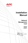
Installation and Quick Configuration Temperature/Humidity Expansion Module AP9341 This manual is available in English on the APC Web site (www.apc.com). Dieses Handbuch ist in Deutsch auf der APC Webseite (www.apc.com) verfügbar. Ce manuel est disponible en français sur le site internet d’APC (www.apc.com). Questo manuale è disponibile in italiano sul sito web di APC (www.apc.com). 本マニュアル<各国の言語に対応する>は APC ウェブサイト (www.apc.com) からダウンロードで きます。 Instrukcja obslugi w jezyku polskim jest dostepna na stronie internetowej APC (www.apc.com). Данное руководство на русском языке доступно на сайте APC (www.apc.com ) Este manual está disponible en español en la página web de APC (www.apc.com). Este manual está disponível em português no site da APC (www.apc.com). Bu kullanim klavuzunun Türkçesi APC web sayfasinda (www.apc.com) mevcuttur. 在 APC 公司的网站上 (www.apc.com) 有本手册的 中文版。 Contents Preliminary Information . . . . . . . . . . . . . . . . . . .1 Overview . . . . . . . . . . . . . . . . . . . . . . . . . . 1 Inventory . . . . . . . . . . . . . . . . . . . . . . . . . . 1 Additional options . . . . . . . . . . . . . . . . . . . 1 Additional documentation . . . . . . . . . . . . . 1 Receiving inspection . . . . . . . . . . . . . . . . . 1 Please recycle . . . . . . . . . . . . . . . . . . . . . . 2 Front and Rear Panel Components . . . . . . . . .3 Front panel . . . . . . . . . . . . . . . . . . . . . . . . 3 Rear panel . . . . . . . . . . . . . . . . . . . . . . . . . 3 Installation—TH Module . . . . . . . . . . . . . . . . . .4 Toolless peg-mount installation . . . . . . . . . 4 Rack-mount installation . . . . . . . . . . . . . . . 4 Installation—Accessories . . . . . . . . . . . . . . . . .6 Sensors . . . . . . . . . . . . . . . . . . . . . . . . . . . 6 Alarm beacon . . . . . . . . . . . . . . . . . . . . . . 9 User inputs (optional) . . . . . . . . . . . . . . . . 9 Connecting TH Modules . . . . . . . . . . . . . . 10 Setting unique identifier numbers . . . . . . . 11 Additional TH Modules . . . . . . . . . . . . . . . 12 Accessing a TH Module . . . . . . . . . . . . . . . . . .13 Upgrading a TH Module . . . . . . . . . . . . . . . . . .13 Specifications. . . . . . . . . . . . . . . . . . . . . . . . . .14 TH Module . . . . . . . . . . . . . . . . . . . . . . . . 14 Sensors . . . . . . . . . . . . . . . . . . . . . . . . . . 15 Warranty . . . . . . . . . . . . . . . . . . . . . . . . . . . . . .16 Limited warranty . . . . . . . . . . . . . . . . . . . 16 Warranty limitations . . . . . . . . . . . . . . . . . 16 Obtaining service . . . . . . . . . . . . . . . . . . . 16 Life-Support Policy . . . . . . . . . . . . . . . . . . . . .18 General policy . . . . . . . . . . . . . . . . . . . . . 18 Examples of life-support devices . . . . . . . 18 Expansion Module i Preliminary Information Overview Connect the Temperature/Humidity Module (TH Module) to the Environmental Manager Main Module to monitor and control the environment through peripheral devices, including temperature and humidity sensors and door contacts. Inventory Quantity Item 1 TH Module (AP9341) 2 Brackets for a standard 19-in rack 4 8-32 × 1/4 Phillips-head screws 2 Toolless mounting pegs (pre-installed) 1 Temperature sensor (AP9335T) 2 Adhesive cable mounts 1 Adhesive temperature-sensor mount 1 Flat-head screw 1 Wall anchor 5 Wire ties Additional options • Temperature Sensor (AP9335T) • Temperature/Humidity Sensor (AP9335TH) • Power Supply (AP9505i) • Alarm Beacon (AP9324) • Door Switch Kit (AP9513) Additional documentation For additional information about the interface, see the Environmental Manager: TH Module User’s Guide, available on the supplied Utility CD or on the APC Web site: www.apc.com. Receiving inspection Inspect the package and its contents for shipping damage and ensure that the parts included in the shipment match all of the parts listed in the inventory table on the previous page. Immediately report any shipping damage to the shipping agent. Report missing contents, damage, or other problems to APC or your APC reseller. Temperature/Humidity Module 1 Preliminary Information Please recycle The shipping materials are recyclable. Please save them for later use, or dispose of them appropriately. 2 Temperature/Humidity Module Front and Rear Panel Components Front panel Use the toolless mounting pegs on the front panel of the TH Module to install it in an APC rack or enclosure without using any U-spaces. T/H Expansion Module Item aem0051a Rear panel Description 24 VDC Input Provides supplemental power for high-current load configurations. User Inputs Connect four sensor devices. Supports the following: • Dry contacts • 0-5 V digital signals See the Environmental Manager: TH Module User’s Guide, available on the included Utility CD or on the APC Web site (www.apc.com), for configuration information Voltage Output Provides 12 VDC or 24 VDC (75 mA) to a connected device. Alarm Beacon Connect an alarm beacon (AP9324). port Connect to the expansion bus for A-Link ports cascading APC TH Modules (AP9341) to a Main Module (AP9340). The bus provides communications and power to the TH Modules using standard CAT5 cabling with straight-through wiring. Identifier # View the identifier number, or LED display change it by pressing the arrow button. Sensor ports Connect a combination of up to six temperature or temperature/ humidity sensors (AP9335T or AP9335TH). Temperature/Humidity Module 3 Installation—TH Module You can install the TH Module in the front or the rear of the rack or enclosure, using either the rackmount option, which uses 1 U of rack space, or the toolless peg-mount option, which uses no U-space (the toolless peg-mount option is available only with APC racks and enclosures). Toolless peg-mount installation This option may not be available with all racks. Note 1. Slide both mounting pegs into the holes located in the cable channel in the rear panel of the rack. 2. Snap the TH Module into place by pushing it downward until it locks into position. Rack-mount installation 1. Remove the toolless mounting pegs located at the front of the unit. 2. Attach the brackets (provided) to each end of the TH Module, using two screws for each bracket. 3. Choose a location in the rack for the TH Module. 4 Temperature/Humidity Module Installation—TH Module The TH Module occupies one Note U-space. A notched hole (or a number, on newer racks) on the rack’s vertical rail denotes the middle of a U-space. 4. Insert caged nuts (provided with the rack) on the vertical mounting rails above a number at the top of a U-space in your rack and below the same number at the bottom of the U-space. 5. Align the mounting holes of the brackets with the installed caged nuts, and insert four mounting screws (provided with the rack) to secure the brackets to the rack. Temperature/Humidity Module 5 Installation—Accessories Sensors Selecting a location for the sensor: Install the sensor in a location that represents the air to be monitored. Avoid placing the sensor anywhere that may affect the sensor reading, such as near windows, room entrances, air ducts, other heat sources, or in direct sunlight. To install a sensor on the vertical rail of an APC rack: aem0184a 1. Determine a location on the vertical rail that will allow you to route and secure the 13-ft (4-m) cord neatly. 2. Peel the backing off the adhesive side of a sensor mount, and press the cable mount firmly to the vertical rail. 3. Thread a wire tie through the sensor mount. 4. Secure the sensor to the sensor mount with the tie. Tighten and trim the wire tie. 5. Thread the sensor cord through the opening in the front post of the rack. 6. Route the cords between the vertical support rail and the side panel. Each sensor cord may be extended to a maximum of 50 ft (15 m), using RJ-45 couplings and standard CAT5 cables. To install a sensor on the door of an APC rack: 1. For optimal sensor performance, install the sensor near the top of the rack door. The bottom of the rack door will not accurately represent the temperature of the air in the room. 6 Temperature/Humidity Module Installation—Accessories aem0073a 2. Thread a wire tie through the door holes, skipping one hole in the middle. If you have a temperature/humidity sensor, place the sensor in the middle of the wire tie, and pull the wire tie around a ridge on the sensor casing. If you have a temperature sensor, pull the wire tie around the sensor cord, about 1/2-in (1 1/4-cm) from the sensor. 3. Tighten and trim the wire tie. aem0074a 4. To route the sensor cord, choose a location on the inside of the door frame that is even with the sensor. 5. Peel the backing off the adhesive side of a cable mount, and press the cable mount firmly to the inside of the door frame. Thread a wire tie through the cable mount, and secure the sensor cord with the wire tie. Tighten and trim the wire tie 6. To secure the sensor cord, choose a location near the middle of the door frame, and repeat step 5. Temperature/Humidity Module 7 Installation—Accessories Note If you use more than one sensor per rack, route the sensor cord farthest from the middle of the rack first. When routing the sensor cord closest to the middle of the rack, secure all sensor cords in the wire tie. aem0076a 7. With the door fully open, thread the sensor cords through the opening in the front post of the rack. 8. Route the cords between the vertical support rail and the side panel. Each 13-ft (4-m) sensor cord may be extended to a maximum of 50 ft (15 m), using RJ-45 couplings and standard CAT5 cables. To install sensors in another location: 1. Use one of the following methods, depending on the type of surface on which you are mounting the sensor: To mount the sensor on a wall or other smooth surface, peel the backing off the adhesive of the sensor mount, and place the sensor mount onto the wall. To mount the sensor on a rough wall or porous surface, first install the wall anchor. Then attach the adhesive sensor mount to the wall anchor using the provided flat-head screw. 2. Thread a wire tie through the sensor mount, and secure the sensor with the tie. Tighten the wire tie and trim any excess. Neatly route the sensor cord and connect the sensor to the APC device. 3. Thread a wire tie through the sensor mount, and secure the sensor with the tie. Tighten the wire tie and trim any excess. 4. Neatly route the sensor cord and connect the sensor to the Main Module or TH Module. 8 Temperature/Humidity Module Installation—Accessories Alarm beacon 1. Install the alarm beacon in a visible position either on the roof of the rack or inside the rack. 2. If you install the beacon on the roof, route its cable through the provided holes, as shown in the following illustration. 3. Plug the cable into the Alarm Beacon port. 4. The cable may be extended to a maximum of 330 feet (100 m), using RJ-45 couplings and standard CAT5 cables. User inputs (optional) There are four user input connection points provided on the TH Module. These inputs use screw terminal connections. Each may optionally be configured as: • 5 V dry contact input (Normally Open [N.O.] or Normally Closed [N.C.]) • 0–5 VDC digital input The following examples show connections for N.O. and N.C. dry contacts. Normally Open (N.O.) Contact Closed for Alarm Normally Closed (N.C.) Contact Open for Alarm Temperature/Humidity Module 9 Installation—Accessories Connecting TH Modules To connect the Main Module to the TH Module: 1. Connect the first TH Module to either port marked A-Link on the rear of the Main Module, using a standard CAT5 (or equivalent) Ethernet patch cable (APC part number 3827BK-10 or equivalent). Do not use a crossover cable for connection. Note A-Link is an APC proprietary CAN (Controller Area Network) bus. Devices compatible with A-Link are not Ethernet devices and cannot coexist on an Ethernet bus with other networking devices, such as hubs and switches. 2. Connect the cable from the Main Module to the top A-Link connector labeled (indicating “input”) on the TH Module. Connect the bottom A-Link connector labeled (indicating “output”), to the next TH Module. 3. Plug an APC terminator (0W04161) into the unused A-Link port at each end of the string. The Main Module does not have to be at the beginning of the chain of cascaded modules. You can cascade TH Modules from both A-Link ports of the Main Module. Always connect the Environmental Manager to the input connector on the TH Module, as described in step 2. The maximum combined length of all A-Link cables is 3280 ft (1000 m). Note Note 10 It is not possible to cascade Main Modules. Install only one Main Module per system. Temperature/Humidity Module Installation—Accessories Main Module (AP9340) TH Module (AP9341) TH Module (AP9341) A-Link port used to plug in an APC terminator. Main Module monitoring connected devices. CAT5 (or equivalent) cable connecting to the TH Module. TH Module to be monitored by the Main Module. CAT5 (or equivalent) cable connecting to the next TH Module in the cascading configuration. This port may be used to link to an TH Module or to plug in an APC terminator. Setting unique identifier numbers Each TH Module should have its own unique identifier number, which is used in the Main Module’s interface to identify and configure this TH Module. Use the arrow button to the right of the Identifier # LED display to set a unique number from 01 to 32 for each TH Module in your system. Do not connect more than 32 TH Modules to the Main Module. When you apply power to the module during the initial installation, all modules will automatically receive a unique identification address. If you manually select duplicate identifiers, the Identifier # LEDs on the duplicated units will flash. Temperature/Humidity Module 11 Installation—Accessories Additional TH Modules Add TH Modules to the Main Module to monitor additional racks. The Main Module can support a maximum of 32 TH Modules (with additional power supplies). Adding power supplies: The first time a TH Module receives power, it requests a unique identification address from the Main Warning Module. It uses this address to communicate with the Main Module. If the TH Module is not part of the system when it receives power for the first time, it cannot ensure that its identifier is unique, and communication problems may arise. To avoid communication problems, connect the TH Module to the Main Module or a TH Module that is part of the system before connecting a stabilized power supply to the 24 VDC Input. Main Module (AP9340) + G N C N 24 12 N O O C D M + –+ 4 2 3 G D D N 0 1 D Voltage Output User Inputs –+ – 1 –+ + – TH Module (AP9341) 3 4 –+ –+ + 24 VDC Input 2 Alarm Beacon Alarm Beacon G D D N 0 1 D aem0078a 1 –+ TH Module (AP9341) Voltage Output User Inputs –+ –+ 24 VDC Input Connect the TH Module to the system. Add a stabilized power supply (AP9505i) where needed. If the system includes beacons or devices attached to the +12 VDC or +24 VDC voltage output connector, attach a stabilized power supply (AP9505i) to the 24 VDC Input of every third TH Module. If the system does not include any beacons or voltage output connections, connect a stabilized power supply (AP9505i) to the 24 VDC Input of every tenth TH Module. 12 Temperature/Humidity Module Accessing a TH Module TH Module data automatically appears on the interface of the Main Module to which it is connected. See the Environmental Manager: TH Module User’s Guide, available on the Utility CD or online at www.apc.com, See also for information on configuring devices connected to your TH Module. Upgrading a TH Module When you upgrade the firmware of the Main Module, all TH Modules connected to it are also upgraded if a firmware upgrade is available for them. During the upgrade, other device operations are suspended. For more information on firmware upgrades, see “How to Upgrade Firmware” in the Environmental See also Manager Main Module Installation and Quick Configuration manual. Temperature/Humidity Module 13 Specifications TH Module Electrical Input voltage, nominal 24 VDC; 50–175 mA Maximum total current draw 175 mA Physical Dimensions (H × W × D) 1.74 × 13.25 × 1.74 in (4.42 × 33.70 × 4.42 cm) Weight 1.50 lb (0.70 kg) Shipping weight 4.00 lb (1.80 kg) Shipping dimensions (H × W × D) 2.62 × 17.75 × 8.87 in (6.70 × 45.00 × 22.50 cm) Environmental Elevation (above MSL) Operating Storage 0 to 10,000 ft (0 to 3000 m) 0 to 50,000 ft (0 to 15 000 m) Temperature Operating Storage 32 to 113°F (0 to 45ºC) 5 to 149°F (–15 to 65°C) Humidity Operating Storage 0 to 95%, non-condensing 0 to 95%, non-condensing Compliance Approvals 14 CE, FCC Part 15 Class A, ICES-003 Class A, VCCI Class A, EN 55022 Class A, EN 55024, AS/NZS 3548 Temperature/Humidity Module Specifications Sensors Temperature (AP9335T) Temperature accuracy ±3ºF (±2ºC), from 32 to 104ºF (0 to 40ºC) Sensor operating temperature 14 to 159ºF (–10 to 70ºC) Maximum length of cable 50 ft (15.2 m) A-Link Maximum length of cable 3280 ft (1000 m) Beacon Maximum length of cable 330 ft (100 m) Temperature/Humidity (AP9335TH), optional Temperature accuracy ±3ºF (±2ºC), from 32 to 104ºF (0 to 40ºC) Humidity accuracy ±4% RH, 20 to 90% RH, at 77ºF (25ºC) ±8% RH, 30 to 80% RH, from 59 to 95ºF (15 to 30ºC) Sensor operating temperature 14 to 159ºF (–10 to 70ºC) User input response time 200 mS Maximum length of cable 50 ft (15.2 m) Temperature/Humidity Module 15 Warranty Limited warranty APC warrants the Temperature/Humidity Module to be free from defects in materials and workmanship for a period of two years from the date of purchase. Its obligation under this warranty is limited to repairing or replacing, at its own sole option, any such defective products. This warranty does not apply to equipment that has been damaged by accident, negligence, or misapplication or has been altered or modified in any way. This warranty applies only to the original purchaser. Warranty limitations Except as provided herein, APC makes no warranties, expressed or implied, including warranties of merchantability and fitness for a particular purpose. Some jurisdictions do not permit limitation or exclusion of implied warranties; therefore, the aforesaid limitation(s) or exclusion(s) may not apply to the purchaser. Except as provided above, in no event will APC be liable for direct, indirect, special, incidental, or consequential damages arising out of the use of this product, even if advised of the possibility of such damage. Specifically, APC is not liable for any costs, such as lost profits or revenue, loss of equipment, loss of use of equipment, loss of software, loss of data, costs of substitutes, claims by third parties, or otherwise. This warranty gives you specific legal rights and you may also have other rights, which vary according to jurisdiction. Obtaining service To obtain support for problems with your Temperature/Humidity Module: 0 1. Note the serial number. The serial number is printed on a label located on the bottom of the unit. 2. Contact Customer Support at a phone number on the back cover of this manual. A technician will try to help you solve the problem by phone. 3. If you must return the product, the technician will give you a return material authorization (RMA) number. If the warranty expired, you will be charged for repair or replacement. 16 Temperature/Humidity Module Warranty 4. Pack the unit carefully. The warranty does not cover damage sustained in transit. Enclose a letter with your name, address, RMA number and daytime phone number; a copy of the sales receipt; and a check as payment, if applicable. 5. Mark the RMA number clearly on the outside of the shipping carton. 6. Ship by insured, prepaid carrier to the address provided by the Customer Support technician. Temperature/Humidity Module 17 Life-Support Policy General policy American Power Conversion (APC) does not recommend the use of any of its products in the following situations: • In life-support applications where failure or malfunction of the APC product can be reasonably expected to cause failure of the life-support device or to affect significantly its safety or effectiveness. • In direct patient care. APC will not knowingly sell its products for use in such applications unless it receives in writing assurances satisfactory to APC that (a) the risks of injury or damage have been minimized, (b) the customer assumes all such risks, and (c) the liability of American Power Conversion is adequately protected under the circumstances. Examples of life-support devices The term life-support device includes but is not limited to neonatal oxygen analyzers, nerve stimulators (whether used for anesthesia, pain relief, or other purposes), autotransfusion devices, blood pumps, defibrillators, arrhythmia detectors and alarms, pacemakers, hemodialysis systems, peritoneal dialysis systems, neonatal ventilator incubators, ventilators (for adults and infants), anesthesia ventilators, infusion pumps, and any other devices designated as “critical” by the U.S. FDA. Hospital-grade wiring devices and leakage current protection may be ordered as options on many APC UPS systems. APC does not claim that units with these modifications are certified or listed as hospital-grade by APC or any other organization. Therefore these units do not meet the requirements for use in direct patient care. 18 Temperature/Humidity Module Radio Frequency Interference Changes or modifications to this unit not expressly approved by the party responsible for compliance could void Warning the user’s authority to operate this equipment. USA—FCC This equipment has been tested and found to comply with the limits for a Class A digital device, pursuant to part 15 of the FCC Rules. These limits are designed to provide reasonable protection against harmful interference when the equipment is operated in a commercial environment. This equipment generates, uses, and can radiate radio frequency energy and, if not installed and used in accordance with this user manual, may cause harmful interference to radio communications. Operation of this equipment in a residential area is likely to cause harmful interference. The user will bear sole responsibility for correcting such interference. Canada—ICES This Class A digital apparatus complies with Canadian ICES-003. Cet appareil numérique de la classe A est conforme à la norme NMB-003 du Canada. Japan—VCCI This is a Class A product based on the standard of the Voluntary Control Council for Interference by Information Technology Equipment (VCCI). If this equipment is used in a domestic environment, radio disturbance may occur, in which case, the user may be required to take corrective actions. この装置は、情報処理装置等電波障害自主規制協 議会(VCCI)の基準に基づくクラス A 情報技 術装置です。この装置を家庭環境で使用すると、 電波妨害を引き起こすことがあります。この場合 には、使用者が適切な対策を講ずるように要求さ れることがあります。 APC Worldwide Customer Support Customer support for this or any other APC product is available at no charge in any of the following ways: • Visit the APC Web site to access documents in the APC Knowledge Base and to submit customer support requests. – www.apc.com (Corporate Headquarters) Connect to localized APC Web sites for specific countries, each of which provides customer support information. – www.apc.com/support/ Global support searching APC Knowledge Base and using e-support. • Contact an APC Customer Support center by telephone or e-mail. – Regional centers: Direct InfraStruXure Customer Support Line (1)(877)537-0607 (toll free) APC headquarters U.S., Canada (1)(800)800-4272 (toll free) Latin America (1)(401)789-5735 (USA) Europe, Middle East, Africa (353)(91)702000 (Ireland) Japan (0) 35434-2021 Australia, New Zealand, South Pacific area (61) (2) 9955 9366 (Australia) – Local, country-specific centers: go to www.apc.com/ support/contact for contact information. Contact the APC representative or other distributor from whom you purchased your APC product for information on how to obtain local customer support. Entire contents copyright 2005 American Power Conversion Corporation. All rights reserved. Reproduction in whole or in part without permission is prohibited. APC and the APC logo are trademarks of American Power Conversion Corporation. All other trademarks, product names, and corporate names are the property of their respective owners and are used for informational purposes only. 990-2380A-001 08/2005 *990-2380A-001*