1
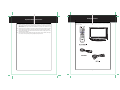
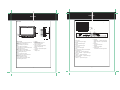
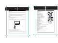
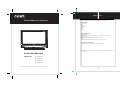
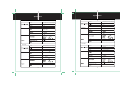
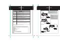
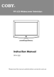
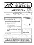
Precautions
Precautions
•
•
rtant a et nstru ti n
rtant a et nstru ti n
FCC Statement
This device complies with Part 15 of the FCC Rules. Operation is subject to the following two
conditions:
(1) This device may not cause harmful interference, and
(2) This device must accept any interference received, including interference that may cause
undesired operation.
WARNING: TO REDUCE THE RISK OF FIRE OR ELECTRIC SHOCK, DO
NOT EXPOSE THIS APPLIANCE TO RAIN OR MOISTURE.
The lightning flash with arrowhead symbol, within an equilateral triangle, is intended
to alert the user to the presence of uninsulated “dangerous voltage” within the
product’s enclosure that may be of sufficient magnitude to constitute a risk of
electric to persons.
The exclamation point within an equilateral triangle is intended to alert the user to
the presence of important operating and maintenance (servicing) instructions in the
literature accompanying the appliance.
For Customer Use:
Enter below the serial number that is located on the
rear of the unit. Retain this information for future reference.
Model No.
TF-TV2617/3217/3717/4217
Note:
This equipment has been tested and found to comply with the limits for Class B digital devices,
pursuant to Part 15 of the FCC rules. These limits are designed to provide reasonable protection
against harmful interference in a residential installation. This equipment generates, uses and can
radiate radio frequency energy and, if not installed and used in accordance with the instructions, may
cause harmful interference to radio communications. However, there is no guarantee that interference
will not occur in a particular installation. If this equipment does cause harmful interference to radio or
television reception, which can be determined by turning the equipment off and on, the user is
encouraged to try to correct the interference by one or more of the following measures:
- Reorient or relocate the receiving antenna.
- Increase the separation between the equipment and receiver.
- Connect the equipment into an outlet on a circuit different from that to which the receiver is
connected.
- Consult the dealer or an experienced radio/TV technician for help
Use of shielded cable is required to comply with Class B limits in Subpart B of Part 15 of the FCC
rules.
Serial No.
CAUTION:
These servicing instructions are for use by qualified service personnel only. To reduce the risk
of electric shock, do not perform any servicing other than that contained in the operating
instructions unless you are qualified to do so. Refer to manual for servicing instructions.
POWER SUPPLY:
Connect one end of the supplied power cable to the AC jack on the back of the unit and other
end to an AC100-240V wall outlet. If you have difficulty inserting the plug, turn it over and
reinsert it, if the unit will not be used for a long time, disconnect the plug from the outlet.
POWER MANAGEMENT:
1. If the player will not be used for a period of time, please disconnect the power.
2. Before plugging the power cord into an AC outlet, make sure that all the connections have been
made.
Do not make any changes or modifications to the equipment unless otherwise specified in the manual.
If such changes or modifications should be made, you could be required to stop operation of the
equipment.
NOTE:
The LCD panel used in this television contains millions of thin film transistors that have been
manufactured using a high-technology process to deliver a crisp, clear, and detailed picture.
Occasionally, a few of these transistors may become stuck or non-active; please note that this does
not affect the performance of the television.
Copyright Protection
Unauthorized copying, broadcasting, public performance, and lending of disks are prohibited. This
product incorporates copyright protection technology that is protected by method claims of certain U.S.
patents and other intellectual property rights owned by Macrovision Corporation and other rights
owners. Use of this copyright protection technology must be authorized by Macrovision Corporation,
and is intended for home and other limited viewing uses only unless otherwise authorized by
Macrovision Corporation. Reverse engineering or disassembly is prohibited.
Important Safety Instructions
•
rtant a et nstru ti n
1.
Read Instructions: All the safety and operating instructions should be read before the product
is operated.
2.
Retain Instructions: The safety and operating instructions should be retained for future reference.
3.
Heed Warnings: All warnings on the product and in the operating instructions should be
adhered to.
4.
Follow Instructions: All operating and usage instructions should be followed.
5.
Cleaning: Unplug this product from the wall outlet before cleaning. Do not use liquid cleaners
or aerosol cleaners. Use a damp cloth for cleaning.
6.
Attachments: Use only attachments recommended by the manufacturer. Use of other attachments may be hazardous.
7.
Water and Moisture: Do not use this product near water (e.g., near a bath tub, washbowl,
kitchen sink, laundry tub, in wet basements, or near a swimming pool and the like).
8.
Accessories: Do not place this product on an unstable cart, stand, tripod, bracket, or table. Use only with carts, stands, tripods, brackets,
or tables recommended by the manufacturer or sold with the product. Any mounting of the product should follow the manufacturer’s
instructions and should use a mounting accessory recommended
by the manufacturer.
9.
A product and cart combination should be moved with care.
Quick stops, excessive force, and uneven surfaces may cause the
product and cart combination to overturn.
10. Ventilation: Slots and openings in the cabinet are provided for ventilation to ensure reliable operation of the product and to protect it from overheating. These
openings should never be blocked by placing the product on a bed, sofa, rug, or other similar
surface. This product should not be placed in a built-in installation such as a bookcase or rack
unless proper ventilation is provided or the manufacturer instructions have been adhered to.
11. Power Sources: This product should be operated only from the type of power source indicated on the rating label. If you are not sure of the type of power supply to your home, consult
your product dealer or local power company. For products intended to operate from battery
power or other sources, refer to the operating instructions.
12. Grounding or Polarization: This product may be equipped with a polarized alternating-current
line plug that has one blade wider than the other. This plug will only fit into the power outlet in
one direction. This is a safety feature. If you are unable to insert the plug fully into the outlet,
try reversing the direction of the plug. If the plug should still fail to fit, contact an electrician to
replace the obsolete outlet. Do not defeat the safety purpose of the polarized plug.
13. Power-Cord Protection: Power supply cords should be routed so that they are not likely to
be walked on or pinched by items placed upon or against them, paying particular attention to
cords at plugs, convenience receptacles, and at the point which they exit from the product.
14. Protective Attachment Plug: The product may be equipped with an attachment plug with
overload protection. This is a safety feature. See the operating instructions for replacement
or directions to reset the protective device. If replacement of the plug is required, be sure the
service technician has used a replacement plug that has the same overload protection as the
original plug as specified by the manufacturer.
Important Safety Instructions
•
rtant a et nstru ti n
15. Outdoor Antenna Grounding: If an outside antenna is connected to the product, be sure the
antenna system is grounded so as to provide some protection against voltage surges and
built-up static charges. Article 810 of the National Electrical Code, ANS/NFPA 70 provides
information with regard to proper grounding of the mast and supporting structure, grounding of the lead-in wire to an antenna-discharge unit, size of grounding conductors, location
of antenna-discharge unit, connection to grounding electrodes, and requirements for the
grounding electrode (see figure).
16. Lightning: For added protection for this product, unplug it from the wall outlet and disconnect
the antenna or cable system during a lightning storm or when it is left unattended and unused
for long periods of time. This will prevent damage to the product due to lightning or power-line
surges.
17. Power Lines: An outside antenna system should not be located in the vicinity of overhead
power lines or other electric light or power circuits, or where it can fall into such power lines
or circuits. When installing an outside antenna system, extreme care should be taken to keep
from touching such power lines or circuits, as contact with them might be fatal.
18. Overloading: Do not overload wall outlets, extension cords, or integral convenience receptacles as this can result in a risk of fire or electric shock.
19. Object and Liquid Entry: Never push objects of any kind into this product through openings
as they may touch dangerous voltage points or shout-out parts that could result in a fire or
electric shock. Never spill liquid of any kind on the product.
20. Servicing: Do not attempt to service this product yourself as opening or removing covers may
expose you to dangerous voltage or other hazards. Refer all servicing to qualified service
personnel.
21. Damage Requiring Service: Unplug this product from the wall outlet and refer servicing to
qualified service personnel under the following conditions: a) when the power-supply or plug
is damaged; b) if liquid has been spilled or if objects have fallen into the product; c) if the
product has been exposed to rain or water; d) if the product does not operate normally by following the operating instructions. Adjust only those controls that are covered by the operating
instructions as improper adjustment of other controls may result in damage and will often
require extensive work by a qualified technician to restore the product to its normal operation;
e) if the product has been dropped or damaged in any way; f) when the product exhibits a
distinct change in performance—this indicates a need for service.
Package Contents
Important Safety Instructions
•
n a in
rtant a et nstru ti n
22.
Replacement Parts: When replacement parts are required, be sure that your service technician has used replacement parts specified by the manufacturer or have the same characteristics as the original part. Unauthorized substitutions may result in fire, electric shock, or
other hazards.
23.
Safety Check: Upon completion of any service or repairs to this product, ask the service technician to perform safety checks to ensure that the product is in proper operating condition.
24.
Wall or Ceiling Mounting: The product should be mounted to a wall or ceiling only as recommended by the manufacturer.
25.
Heat: The product should be situated away from heat sources such as radiators, heat registers, stoves, or other products (including amplifiers) that produce heat.
Please make sure the following items are included with your LCD TV/monitor. if any items are missing,
contact your dealer.
FAV+
FAV-
••
023
LCD Television
1
Unit View
Unit View
nit ie
nit ie
Rear Panel
Front Panel
10
>
1
2
9
8
3
4
5
<
6
8
9
11
VIDEO-OUT AUDIO-R
7
HDMI-2
1
7. POWER
Press to turn the power on/off.
8. Remote Sensor
Sense the remote signal.
9. Power On Indicator
Lights green during normal usage.
Lights red during standby.
10. Screen
Present the high resolution picture.
11. Speaker
Output sound.
1. MODE/ENTER
Press to shift modes. While working with the
menu, press to confirm settings.
2. MENU
Press to display the system menu.
3. CH+
Press to skip channels forward.
It also works as the up direction button while
working with the menu.
4. CHPress to skip channels backward.
It also works as the down direction button
while working with the menu.
5. VOL+
Press to increase the volume.
It also works as the right direction button
while working with the menu.
6. VOLPress to decrease the volume.
It also works as the left direction button
while working with the menu.
2
HDMI-1
3 4
Y
5
Pb
Pr
6
AUDIO-R
7
AUDIO-L
AUDIO-L
S-VIDEO
OPTICAL
10 11 12
9. AV Output
VIDEO-OUT - - output the video signal.
AUDIO-L, AUDIO-R - - Output the audio
signal.
10. S-VIDEO
Input the S-Video signal.
11. OPTICAL
Output the audio signal.
12. Antennal Jack
Connect with the TV RF signal source.
1. Power Jack
Connect with the power supply.
2. HDMI2
Input the audio/video signal.
3. HDMI1
Input the audio/video signal.
4. PC Audio In
Input the PC audio signal.
5. VGA
Connect with the VGA port on the computer.
6. Component Input
YCb/Pb Cr/Pr - - Input the video signal.
AUDIO-L, AUDIO-R - - Input the audio signal.
7. AV1 Input
VIDEO-1 - - Input the video signal.
AUDIO-L, AUDIO-R - - Input the audio signal.
8. AV2 Video Input
VIDEO-2 - - Input the video signal.
4
3
VIDEO-1
Remote Control
Remote Control
e
te
ntr
Remote Control
Preparation
- Remove the battery compartment cover located on the rear of the remote control. Insert 2 x “AAA”
batteries, making sure to match their polarities (+/-) to the markings on the inside of the compartment.
Replace the cover.
- Batteries in the remote will last for approximately 6 months under normal use. Replace the batteries if
the remote control does not work. Do not mix old with new batteries, or different types of batteries.
- Remove the batteries from the remote if it will not be used for a long period of time.
Warnings:
The battery used in this device may present a fire or chemical burn if mistreated. Do not recharge,
disassemble, incinerate, or heat the battery (~212ºF).
Keep batteries away from children.
Using the Remote Control
To use the remote, point it at the remote sensor of the player. Operate the remote within 20 feet of the
sensor and at an angle of ±30 degrees.
7
s
The operating distance may vary depending on the brightness around.
Notes:
Do not point bright lights directly at the remote control sensor.
Do not place objects between the remote control unit and the remote control sensor.
Do not use this remote control unit while simultaneously operating the remote control unit of any other
equipment.
e
ntr
Remote Control Drawing
1. POWER button
Press to turn the power on/off.
2. Numeric Keypad
1
Press to input data.
3. S.Mode
Press to select the audio mode.
4. VOLUME +/- button
2
Press to adjust the sound level.
5. MENU button
Press to show the system menu.
3
6. Sleep button
4
Press to access the sleep timer.
7. FAV + button
5
Press to skip the favorite channels forward.
8. FAV button
Press to display the favorite channel list.
6
9. FAV - button
Press to skip the favorite channels backward.
7
10. EPG button
8
Access the Electronic Program Guide.
9
11. SCALE button
10
Adjust the display effect.
11
12. STILL button
12
Press to freeze the picture.
13. MODE button
Press to select the working mode.
14. RETURN button
Press to return to the previously viewed channel.
15. P.Mode
Select the picture mode.
16. CHANNEL+/-button
Press to skip channels.
17. Direction &OK
While working with the system menu, press the direction buttons to
move the cursor and press OK to confirm settings.
18. EXIT button
Press to exit the system menu.
19. MTS button
Set the ATV audio mode or the DTV audio language.
20. CH-LIST
Press to display the channel list.
21. V-CHIP
Access the LOCK menu.
22. CAPTION
Select the closed caption mode. (CC Off, CC On, CC On Mute)
23. MUTE button
Press to muffle/release sound.
24. INFO
Press to show the current working information.
5
6
te
13
14
15
16
17
18
FAV+
19
20
21
22
23
24
FAV-
023
Cable Connections
Cable Connections
a e
nne ti ns
Figure. Cable connections
Figure. Cable connections
Set the unit to the relative input mode
to enable the signal pass.
External Moniter
Amplifier equipped with a Dolby Pro Logic Surround
HDMI-2
HDMI-1
VIDEO-2
AUDIO-R
AUDIO-L
Y
Pb
Pr
VIDEO-OUT AUDIO-R
VIDEO-1
AUDIO-R
AUDIO-L
AUDIO-L
S-VIDEO
OPTICAL
Antenna/Power Connection
1. Connect TV RF sources to the antenna port. TV RF signals include: receiving antenna/CATV net.
You can use 75 Ohm coaxial cable to connect outdoor antenna.
2. Insert one end of the supplied power cord to the player’s power jack and the other end to
S-Video Input
The S-Video port is capable of accepting signals from standard video sources
(e.g., cable/satellite boxes, DVD players, VCRs, etc.)
1. Connect the S-Video port by the S-Video cable(not supplied) to input the video signal.
2. Connect the AUDIO-L/R port by the supply AV cable to input the audio signal.
AV Input/Output
The CVBS port is capable of accepting signals from standard video sources(e.g., cable/satellite boxes,
DVD players, VCRs, etc.)
AV Input - 1. Connect the VIDEO-1/2 port by the supplied AV cable to input the video signal.
2. Connect the AUDIO-L/R port by the supplied AV cable to input the audio signal.
AV Output - 1. Connect the VIDEO-OUT port by the supplied AV cable to output the video signal.
2. Connect the AUDIO-L/R port by the supplied AV cable to output the audio signal.
OPTICAL Output - Digital Audio Output Connector
When MPEG audio or Dolby Digital audio is played, Dolby Digital bitstream or MPEG audio bitstream
is sent to the player’s digital audio output connector. When the player is connected to a Dolby or
MPEG audio decorder via this output socket, you can enjoy theater-quality audio in your home. An
optical audio cable is required when a Dolby Digital decoder or MPEG audio decoder is used.
For your reference
Dolby Digital is a digital sound compression technique developed by the Dolby Laboratories Licensing
Corporation. Supporting 5.1-channel surround sound, as well as stereo (2-channel) sound, this
technique enables a large quantity of sound data to be efficiently recorded on a disc.
Caution for the optical digital audio output connector:
Do not connect an amplifier(with an optical digital input connector) which does not contain the
Dolby Digital or MPEG audio decoder.
VGA Input
The VGA port of the TV is capable of accepting high-definition signals from computers with a VGA
output jack. When used as a computer moniter, connect the VGA jack and the PC Audio In jack. A
15-Pin D-Sub cable (not supplied) is required for VGA connection and a 3.5mm stereo audio cable (not
supplied) is required for the audio connection.
the 110-240V AC wall outlet.
Compoent Input (Y Cb/Pb Cr/Pr)
The component port is capable of accepting high-definition signals from standard video sources
(e.g., cable/satellite boxes, DVD players, VCRs, etc.)
1. Connect the Y/Pb/Pr port by the component cable (not supplied) to input the video signal.
2. Connect “AUDIO-L” ”AUDIO-R” port by the supply AV cable to input the audio signal.
The red and the white plug of the AV cable is for the audio conneciton and the yellow plug for the
video connection.
HDMI 1/2 Input
HDMI (High Definition Multimedia Interface) is a new type of connection that transmits digital
audio and video signals simultaneously over a single cable.
A HDMI cable(not supplied) is required for the HDMI connection.
These HDMI input connectors are capable of receiving video at resolutions up to 1080p
(1080-progressive).
7
8
TV Function
TV Function
Fun ti n
Fun
Funti tin n
Audio Menu
TV Function
Preparations
1. Connect the cables.(Refer to the “Cable Connections” section for details).
2. Press the POWER button to turn on the player.
3. Press the MODE button to select the TV signal mode.
4. Press the CH+/- buttons to skip channels.
ITEM
DESCRIPTION
Sound Mode
Bass
Treble
Balance
MTS
Set the sound mode. (Standard, Music, Movie, Personal).
Adjust the bass.
Adjust the treble.
Adjust the sound balance.
Set the MTS audio for the ATV mode.
(Mono, Stereo, SAP)
Set the audio language. (English, French, Spanish)
Audio Language
TV Setup Menu
Various features can be preset through the TV setup menu. TV setup menu consists of PICTURE,
AUDIO, TIME, SETUP, LOCK as well as CHANNEL, Press MENU to display the setup menu, press
the left/right direction button to select the desired submenu, press OK to enter.
While working with the menu,
1. Press the up/down direction button to select.
2. Press the left/right direction button to adjust.
3. Press MENU to exit/return to the previous menu.
Time Menu
ITEM
DESCRIPTION
Sleep Timer
The unit will shut down automatically on the Sleep Time.
The available option is 5/10/15/30/45/60/90/120/180/240 min, Off.
The count down would start immediately after setting.
You can access this function by repeatedly pressing the SLEEP button
on the remote also. To check the timer left, press the SLEEP button on
the remote once. To cancel the sleep timer, set the timer to Off.
Set the DTV time zone.
(Pacific, Alaska, Hawaii, Eastern, Central, Mountain)
Time Zone
Daylight Saving
Time
Clock
Set the DTV daylight saving function on/off.
Display the DTV clock information.
Setup Menu
Picture Menu
ITEM
DESCRIPTION
Picture Mode
Contrast
Brightness
Color
Tint
Sharpness
Color Mode
Setup the picture mode (Personal, Standard, Dynamic, Soft).
Adjust the display contrast
Adjust the display brightness
Adjust the display color
Adjust the display tint
Adjust the image sharpness
Set the color mode (Normal, Warm, Cool).
10
ITEM
DESCRIPTION
Menu Language
Transparency
Zoom Mode
Noise Reduction
Closed Caption
Set the menu language.
Set the transparency on/off.
Set the screen effect. (4:3, Zoom, Cinema, Normal, 16:9)
Adjust the screen noise appearance. (Weak, Middle, Strong, Off)
Press the right direction button to access the closed caption menu,
CC Mode - Set the CC mode. ( Off, On, CC On Mute)
Basic Selection - Set the basic CC type. (CC1~4, Text 1~4)
Advanced Selection - Set the advanced CC type for DTV. (Service 1~6)
Option - - Press the right direction button to enter the option menu,
Under the option menu, set Mode as Custom to edit the DTV
CC type to your own liking.
Set DLC on/off
Set the player to the factory default.
DLC
Restore Default
11
TV Function
TV Function
Fun ti n
Fun ti n
Lock Menu
ITEM
DESCRIPTION
Enter Password
RRT Setting
You are required to enter the 4-digit password to access the Lock menu.
The initial password is 0000.
To change the password, input the old password - - > input the new
password - - >verify again.
Please remember the password since the players’s reset function would
not revert the password.
Set the system lock funtion on/off.
Set the lock function on to access the parental control setup.
Setup the US parental control.
TV(TV Rating) - Y, Y7, G, PG, 14, MA.
Press the direction buttons to move between options, press OK to set
block. To release, press OK again.
MPAA(Movie Rating) - PG-13, R, NC-17, X, N/A, G, PG)
Press the left/right direction button to set the movie rating.
Setup the canada parental control
Canada English - G, PG, 14+, 18+, E, C, C8+.
Canada French - E, G, 8ans+, 13ans+, 16ans+, 18ans+.
Set the rating region table.
Reset RRT
Restore RRT to the default.
Change Password
System Lock
US
Canada
Channel Menu
ITEM
DESCRIPTION
Air/Cable
Auto Scan
Setup the antenna type as Air or Cable.
Search channels automatically.
Press the right direction button to start searching, press MENU to stop.
When use Cable system, you need to select the cable system before start auto
scan. The available options - AUTO, STD, IRC HRC .
Make the favorite channels collection. Press the right direction button to access
the Favorite List.
Press the up/down direction button to select the desired channel.
Press OK to set it as the favorite channel. To release, press OK again.
Press the left/right button to turn pages in the FAV list.
Hide the unwanted channels. Press the right direction button to access the
Show/Hide List
Press the up/down direciton button to select the channel, press OK to hide the
channel, press OK again to release.
Press the left/right button to turn pages in the Show/Hide list.
Favorite
Show/Hide
Channel No
Press the left/right direction button to select the channel.
Channel Label
Edit the channel label.
1. Select “Channel No”, press the left/right direction button to select
the channel.
2. Select “Channel Label”, press the right direction button to show the edit menu.
In the menu, press the left/right direction button to move left/right,
Press the up/down direction button to select.
DTV Signal
Display the DTV signal intensity.
13
12
AV Function
PC Function
Fun
Funti tin n
PC Function
Fun ti n
AV Function
PC Function
The player’s AV function consists of the AV IN function and the AV OUT function. You can not only
enjoy programs from external input sources through the AV IN function but can also transmit the
player’s signal to the external monitor using the AV OUT function.
1. Connect the external AV signal source or monitor. Refer to the “Cable Connection” section for
details
2. Press the MODE button to select the relevant mode (AV1, AV2, S-Video, Component, HDMI1,
HDMI2)
NOTE: The AV OUT function is only available for the AV1, AV2, S-Video mode.
You can use the unit’s TFT LCD as your computer’s monitor.
1. Shut down both the unit and the computer. Connect the VGA jack and PC Audio In jack. See the
“Cable Connection” section.
2. Turn on the units and the computer. Press the MODE button to select VGA
PC Setup Menu
AV Setup Menu
Various features can be preset through the PC menu.
Press the MENU button to display the PC menu.
PC setup menu consists of PICTURE, AUDIO, TIME as well as SETUP.
Press the left/right direction button to select the desired sub-menu, press OK to enter.
Various features can be preset through the AV menu.
Press the MENU button to display the AV menu.
AV setup menu consists of PICTURE, AUDIO, TIME, SETUP as well as LOCK.
Press the left/right direction button to select the desired sub-menu, press OK to enter.
The LOCK setup menu is only available for the AV1, AV2 and S-Video mode.
While working with the menu
1. Press the up/down direction buttons to select the desired item.
2. Press the left/right direction button to adjust.
3. Press MENU to exit/return to the previous menu.
While working with the menu
1. Press the up/down direction buttons to select the desired item.
2. Press the left/right direction button to adjust.
3. Press MENU to exit/return to the previous menu.
NOTE: Please see the TV section for the menu descriptions
Adjust the PC Screen
NOTE: Please see the TV section for the menu descriptions
14
Upon switching to the PC mode, the moniter will be automatically regulated for a
proper functioning. If the result is not up to your expectation, please perform the
following steps to adjust the screen manually .
1. Enter the “Advanced” sub-menu from the SETUP menu.
Select “Auto” and press the left/right direction button to adjust the
monitor automatically.
2. Or if you still have problem with the monitor after, adjust “H-Pos”, “V-Pos”,
”Clock“ as well as “Phase” accordingly under the SETUP menu.
15
Main Features
Main Features
TFT LCD Widescreen Television
This product incorporates the LCD display and the TV receiver in one system.
Multiple Mode
TV (ATV, DTV)
AV1
AV2
S-VIDEO
COMPONENT
HDMI1
HDMI2
VGA
High Quality Property
High Resolution
Adopt an MPEG2 decoding format to achieve horizontal resolution more than 500 lines.
Superior sound
Built-in Dolby Digital decoder to output high quality sound effects.
Screen
Support the picture size of a normal screen (4:3) and a wide screen (16:9)
LCD (Liquid Crystal Display)
Designed with color TFT liquid crystal display clearly shows the data.
••
NOTE: It is normal for a TFT screen to experience some light or dark spots appearing on the LCD
Instruction Manual
Model No :
TF-TV 2617
TF-TV 3217
TF-TV 3717
TF-TV 4217
Please read this manual before connection and use.
screen.
Specifications
Specifications
e i i ati n
•
e i i ati n
•
TF-TV 3717
TF-TV 2617
Active Area
Active Area
820.8(H)x461.7(V)mm (37.07” Diagonal)
575.769(H)x323.712(V)mm (26” Diagonal)
1920x1080
1366X768
Display Color
16.7M
Pixel Pitch
0.1405(H)x0.4215(V)mm
TV Characteristic
Display Color
16.7M
Pixel Pitch
0.1425(H)x0.4275(V)mm
TV Characteristic
NTSC, ATSC
NTSC, ATSC
75
Antenna impedance
75
Antenna impedance
unbalance
unbalance
200 W
110 W
8
8
10
8
+
10
10
35.6” X 13.0” X 26.8”
26.1” X 9.2” X 19.7”
TF-TV 4217
TF-TV 3217
Active Area
Active Area
697.685(H)x392.256(V)mm(31.5” Diagonal)
930.24(H)x523.26(V)mm (42.02” Diagonal)
1920x1080
1366X768
Display Color
16.7M
Pixel Pitch
170.25(H)x510.75(V)
m
Display Color
16.7M
Pixel Pitch
0.1615(H)x0.4845(V)mm
TV Characteristic
TV Characteristic
NTSC, ATSC
NTSC, ATSC
75
Antenna impedance
75
Antenna impedance
unbalance
250 W
130 W
8
8
10
+
40.3” X 13.0” X 28.5”
31.3” X 9.2” X 22.9”
16
unbalance
17
8
10
10
Troubleshooting
•
Cable Connections
r u e
tin
Figure. Cable connections
Make sure the unit has been powered on manually.
Check if the power cord has been properly connected to the power outlet.
Check if the main power has been switched on.
NOTE:
1. Be sure to have all necessary connections properly
done before connect the power supply.
2. When input/out the AV signal, refer to the manual of
the external sources as well.
Component Input
Try another TV channel
Check if the system connection is proper and secure.
Check if the connection cables are damaged.
Increase the volume.
Check if the MUTE function of the unit has been activated.
Check if the sound system has been properly set.
Check if the AV audio signal input cable has been connected properly.
Color distorted
AUDIO-R
AUDIO-L
Y
Pb
Pr
VIDEO-OUT AUDIO-R
VIDEO-1
AUDIO-R
AUDIO-L
AUDIO-L
S-VIDEO
OPTICAL
NOTE:
We supply the AV cable and the power cord
with this product.
The white/red plug of the AV cable is for the
audio connection and the yellow plug for the
e
video connection.
The white/red plug of the AV cable can also
be used separately to input the audio signall
in the S-video/Component connection.
Reset the color system of the unit.
Check if the system has been properly connected.
Check if the AV video signal input cable is connected properly.
Picture and
sound are interfered
Check if the system has been properly connected.
If using antenna, adjust the antenna.
Remote control does
not work
Make sure the POWER button on the unit has been turned on manually.
Remove the obstacles between the remote control and the player.
Point the remote control towards the remote sensor on the player.
Check if the batteries of the remote control have been loaded with correct polarities.
Replace the batteries of the remote control.
Malfunction
VIDEO-2
S-Video Input
VIDEO-2
AUDIO-R
AUDIO-L
Y
Pb
Pr
VIDEO-OUT AUDIO-R
VIDEO-1
AUDIO-R
AUDIO-L
AUDIO-L
S-VIDEO
OPTICAL
Should the player develop a malfunction, unplug the player for 30 minutes. After that,
power on the player and the restore function should reset the player.
AV2 Input
AV Input/Output
Design, specifications and manual are subject to change without prior notice.
P/N: 907-FV26-1700-00R
If you have a problem with this device, please read the troubleshooting guide section and
check our website at www.cobyusa.com for Frequently Asked Questions (FAQs) and
firmware updates. If these resources do not resolve the problem, please contact Technical
Support.
Address
COBY Electronics Technical Support
56-65 Rust Street
Maspeth, NY 11378
Email
[email protected]
Web
www.cobyusa.com
Phone
800-727-3592: Weekdays 8:30AM -9:00PM EST
Saturdays 9:00AM -5:30PM EST
718-416-3197: Weekdays 8:00AM -5:30PM EST
18
AV Output
VIDEO-2
AUDIO-R
AUDIO-L
Y
Pb
Pr
VIDEO-OUT AUDIO-R
VIDEO-1
AUDIO-R
AUDIO-L
AUDIO-L
S-VIDEO
OPTICAL
External Monitor
AV1 Input
9
VIDEO-2
AUDIO-R
AUDIO-L
Y
Pb
Pr
VIDEO-OUT AUDIO-R
VIDEO-1
AUDIO-R
AUDIO-L
AUDIO-L
S-VIDEO
OPTICAL
Table of Contents
•
a e
ntents
Table Of Contents
Precautions
Important Safety Instructions
Package Contents------------------------------------------------------------------------------------------------------ 1
Main Feature------------------------------------------------------------------------------------------------------------ 2
Unit View----------------------------------------------------------------------------------------------------------------- 3-4
Remote Control -------------------------------------------------------------------------------------------------------- 5-6
Cable Connections----------------------------------------------------------------------------------------------------- 7-9
TV Function-------------------------------------------------------------------------------------------------------------- 10-13
AV Function-------------------------------------------------------------------------------------------------------------- 14
PC Function-------------------------------------------------------------------------------------------------------------- 15
Specifications ----------------------------------------------------------------------------------------------------------- 16-17
Troubleshooting ---------------------------------------------------------------------------------------------------------18