1
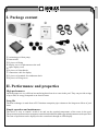
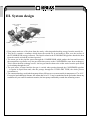
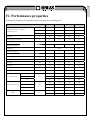
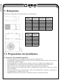
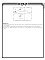
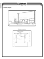
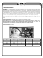
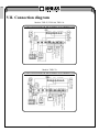
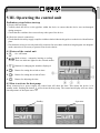
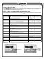
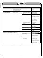
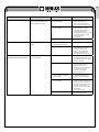
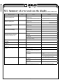
EN
SWIMMING POOL HEAT PUMP
(THP 55, THP 100, THP 120, THP 170)
INSTALLATION
AND
USER GUIDE
i
Read the instructions
EN
Contents
I.
II.
III.
IV.
V.
VI.
VII.
VIII.
IX.
X.
XI.
XII.
XIII.
Package content ..................................................... 3
Performance and properties ................................... 3
System design ........................................................ 4
Performance properties .......................................... 5
Dimensions ............................................................ 6
Preparations for installation ................................... 6
Connection diagram ............................................. 10
Operating the control unit.....................................11
Instructions........................................................... 15
Checks ................................................................. 16
Problem solving .................................................. 17
Summary of error codes on the display................ 20
Maintenance......................................................... 21
Thank you for choosing our product and for your trust in our company. To ensure that you can fully enjoy
the product, please read these instructions carefully and strictly follow the user guide so as not to damage the
device and to avoid unnecessary injuries.
2
EN
I. Package content
②
①
④
③
⑤
⑥
⑧
⑨
⑦
① swimming pool heat pump
② instructions
③ 2 pieces of fitting
④ display cover for placement on the wall
⑤ spare display cover
⑥ 4 pieces of silent blocks
⑦ connection cable for display
⑧ 2 pieces of terminals fro condensate drain
⑨ 4 pieces of fixing srews
II. Performance and properties
High performance
Our heat pumps are very efficient in transferring heat from air to water in the pool. They can provide savings
of up to 80% in energy compared to an electric heater.
Long life
The heat exchanger is made from a PVC/titanium composite pipe resistant to the long-term effects of pool
water.
Simple operation and maintenance
The device is easy to control: switch it on and set the required temperature of the water in the pool.
The system incorporates a microcomputer control unit which allows all the operational parameters to be specified.
The state of operation can be displayed on the control unit through an LED display.
3
EN
III. System design
colder air depleted
of energy
compressor
swimming pool
pump
swimming pool cleaner
hot air
ventilator
condenser
water heat exchanger
capillary tube
evaporator
(energy collector)
• Heat pumps make use of free heat from the sun by collecting and absorbing energy from the outside air.
• This device contains a ventilator which draws the outside air in and makes it flow over the surface of
the EVAPORATOR (energy collector). The liquid coolant in the EVAPORATOR pipeline absorbs the heat
from the outside air and the coolant vaporises.
• The warm gas in the pipeline passes through the COMPRESSOR which gathers the heat and increases
the temperature to generate very hot gas which then passes to the CONDENSER (water heat exchanger).
This is where the heat exchange occurs - the hot gas transfers heat to the colder water from the pool which
is circulating through the coil.
• The pool water is heated and the hot gas is cooled when passing through the CONDENSER pipeline
– it regains its liquid form and, after the passage through the CAPILLARY TUBE, the whole process
recommences.
• The current technology used in the heat pump allows efficient use even at an outside air temperature of 7 to 10 ºC.
For tropical and subtropical climates, this means that 26 to 32 ºC may be maintained in the pool under almost any
conditions all year round. In northern countries, the heat pump considerably extends the swimming season.
4
EN
IV. Performance properties
Performance properties of a monoblock-type heat pump for swimming pools
Code
THP 55
THP 100
THP 120
THP 170
W
5500
9900
11800
17300
BTU
19000
34000
41300
59500
C.O.P.
≥4,5
≥5,1
≥4,5
≥4,7
Heat input
W
1240
1940
2650
3670
Operating current for heating
A
5,5
9,6
13,3
18
Nominal heat output - at an outside
temperature of 15°C
Current supply
V/phase/Hz
220-240/1/50
Number of compressors
1
Compressor
1
1
Rotary
Number of ventilators
1
Scroll
1
1
1
1
W
25
50
50
50
Ventilator speed
RPM
950
950
950
950
Noise
dB(A)
53
55
57
59
Mains pipe
mm
50
50
50
50
Water flow
m3/h
2-4
4-6
6-8
8-10
Decrease in water pressure
kpa
20
20
20
20
Coolant (R407C)
kg
0,8
1,3
1,3
2,1
935
1090
1090
1165
360
370
370
470
H
550
615
615
685
L
1060
1140
1140
1195
380
400
400
485
600
660
660
730
40
62
65
99
48
71
77
104
Input of ventilators
L
Net dimensions
Packaged dimensions
W
W
mm
mm
H
net
Weight
kg
gross
5
EN
V. Dimensions
Dimensions of heat pumps (monoblock-type) for swimming pools
Model
THP 55
THP 100
THP 120
L
1000
1090
1090
W
360
370
370
Dimension
H
550
612
612
A
330
340
340
B
680
640
640
E
81
84
84
F
200
270
270
Unit: mm
Model
THP 170
Dimension
L
1165
W
470
H
685
A
440
B
760
F
325
G
81,5
Unit: mm
VI. Preparations for installation
6.1 Selection of the installation position
• The heat pump has to be installed in a spacious and well ventilated place.
• Its position has to guarantee adequate free space for the exhaust (the location of the air inlet is shown
in the diagram on the next page).
• The heat pump has to be situated close to a drain or vent so as to make water discharge easier.
• The installation base or brace has to be firm enough to ensure smooth operation of the device.
• Make sure the device, when installed, is situated vertically, without any inclination.
• Do not install the device in places where there is contamination, corrosive gas or where dirt or fallen
leaves accumulate.
• The heat pump must not be installed in the vicinity of an inflammable or explosive environment or
near things that are a common cause of fire.
• Maintain the distances from obstacles as indicated with arrows in the picture below.
6
EN
air
inlet
min. 1000 mm
air
inlet
min. 1000 mm from above
min.
1000 mm
min.
1000 mm
air
outlet
min. 2000 mm
Requirements for free space around the horizontal heat pump
WARNING:
• Do not put your hand or any object into the air outlet or ventilator, as this could damage the device and
cause an injury.
• In the event of any abnormalities, switch off the device immediately and contact an expert technician.
• If needed, you should place barriers next to the device to keep children away from the running heat
pump.
7
EN
6.2 Fitting diagram
heat pump
water treatment
side joining valve
output
input
input for
power cable
discharge pipe
for condensed water
discharge swimming pool
spout
water feed
water input
water pump
Discharge connection
CIRCULATION
T
o
t
h
e
s
w
i
m
m
i
n
g
p
o
o
l
F
r
o
m
Valve 1
t
h
e
Valve 2
Valve 3
from
to
HEAT PUMP
8
f
i
l
t
e
r
filter
EN
6.3 Electrical connection
IMPORTANT: The installation and connection of this device to the power supply can be provided only by
authorized person according to order publication no. 50/1978 sb. Although the heat pump is electrically
insulated from the rest of the unit, this fact only prevents the passage of electrical current to or from the water
in the swimming pool. It is still necessary to earth the unit to protect yourself against short-circuit inside
the unit. Ensure the appropriate earthing.To supply voltage please prepend circuit broker with current value
according to type of heat pump you are connecting, and current protektor with residual current 0,03A.
Before connecting the unit, check whether the electrical mains voltage corresponds to the voltage of the heat
pump.
For horizontal models: remove the panel to the right of the ventilator aperture.
Please connect the wires to terminal block marked as source power A second terminal is located next to
this connector labelled „water pump“, which a filtration pump can be connected to (max. 5 A / 230 V). This
connection allows you to control the operation of the filtration pump via the heat pump.
Various possibilities: see table.
Model
Voltage (V)
Circuit breaker (A)
Nominal current (A)
Cable diameter (mm2)
THP55
220-240
10
5,7
2 x 2,5 + 2,5
THP100
220-240
16
9,7
2 x 2,5 + 2,5
THP120
220-240
20
12,7
2 x 4,0 + 4,0
THP170
220-240
32
17,2
2 x 6,0 + 4,0
9
pro max. délku 15 m
EN
VII. Connection diagram
Models: THP 55, THP 100, THP 120
CONNECTION DIAGRAM FOR THE SWIMMING POOL THERMAL PUMP
four-way valve
ventilator
WATER
PUMP
temperature of incoming water
temperature of outgoing water
POWER SUPPLY
electric heater
coil temperature
high pressure switch
low pressure switch
flow switch
outside air temperature
electric
remote
control
pump
Models: THP 170
CONNECTION DIAGRAM FOR THE SWIMMING POOL THERMAL PUMP
four-way valve
ventilator
pump
electric heater
start
relay
WATER
PUMP
10
temperature of incoming water
temperature of outgoing water
POWER SUPPLY
coil temperature
high pressure switch
low pressure switch
flow switch
outside air temperature
electric
remote
control
EN
VIII. Operating the control unit
Preliminary steps before start-up
A) Inspect the heat pump
• Visually check the device or the pipeline within the device to ensure that the device was not damaged
during transport.
• Check that the ventilator does not touch any other part of the device.
B) Check the electric connections
• Check that the electricity supply complies with the technical data in this guide or on the device identification
plate.
• Check that the wiring is correctly and safely connected in accordance with the wiring diagram. An adequate
earth connection is necessary to protect from electric shocks.
8.1 Picture of the control unit
A.
On / off button.
B.
Mode selector – automatic, heating or cooling.
There are indicator lights for the selected modes.
C.
or
Buttons for changing the numbers displayed.
D.
Button for setting the switch-on time.
E.
Button for setting the switch-off time.
F.
Button for adjusting the time.
8.2 How to activate the heat pump
When connected to a power supply, the control unit will show the time. This means the device is in
standby mode. Pushing the button
will activate the heat pump. The control unit display will now show
the temperature of the input water.
Standby
Operation
11
EN
NOTE: In order for the unit to be able to heat the swimming pool (or spa), the filtration pump must be in
operation in order for water to be able to circulate via the heat pump. The heat pump will not start without
circulation.
After checking all connections, you should follow the steps as set out below:
1. Switch on the filtration pump. Check whether any water is leaking out and check the flow to and from
the swimming pool.
2. Connect the power supply to the unit and then press the ON/OFF button on the electronic control panel.
After a short time delay, the unit should start up.
3. After the unit has been running for a few minutes, check whether the air coming out of it is cooler.
4. Check the functioning of the flow switch as follows: switch off the filtration pump when the unit
is running. The unit should also automatically switch off.
5. The whole unit and the filtration pump will operate for 24 hours a day until the required water temperature
in the swimming pool is achieved. After the set temperature is achieved, the unit switches itself off.
The unit then automatically starts (if the filtration pump is working) if the water temperature in
the swimming pool drops by more than 1 °C below the set temperature.
!!! It may take several days for the water to reach the required temperature depending on the initial
water temperature in the swimming pool and the air temperature. You can shorten this time significantly
by covering the swimming pool.
Flow switch
The unit is equipped with a flow switch, which switches on if sufficient amounts of water pass through
the unit and switches off again if the water flow is too low (e.g. if the filtration pump is switched off). This
system avoids only water found in the heat pump itself being heated.
Condensation
When heating the water in the swimming pool using the heat pump, the incoming air is significantly cooled,
which could cause condensation on the ribs of the evaporator. Condensation amounts may reach several
litres per hour in the event of high atmospheric moisture. This condition is sometimes incorrectly regarded
as leakage of water.
12
EN
8.3 How to change the mode
Press the
button to change the mode to automatic, heating or cooling. The appropriate indicator light
will be illuminated on the right side of the control unit.
8.4 How to check the settings and the current measured values
In the standby mode or operation mode, use the buttons
measured values
Parameter
or
to find the parameter 0-A and the current
Meaning
Scope
Factory setting
00
Required water temperature in cooling mode
8–28 °C
12 °C
01
Required water temperature in heating mode
15–40 °C
40 °C
02
Defrosting cycle
30–90 min.
45 min.
03
Set temperature on the evaporator for start of defrosting
–30–0 °C
–7 °C
– not displayed
04
Set temperature on the evaporator for end of defrosting
2–30 °C
13 °C
05
Maximum duration of defrosting
1–15 min.
8 min.
06
Number of compressors in the system
1–2
1
07
Restart after power failure
0–1
1 (ano)
08
Type: only cooling 0/
Heating and cooling 1/
Heating and cooling + supplementary heating 2/
Only heating 3/
0–3
1
09
Various water pump operating modes:
Water pump working constantly 0/
Water pump working in harmony with the heat pump 1/
0–1
0
A
Required water temperature in automatic mode
8–40 ºC
28 ºC
B
Actual temperature of incoming water
-9 +90 ºC
C
Actual temperature of outgoing water
-9 +90 ºC
D
Pipe water temperature in the system 1
-9 +90 ºC
E
Pipe water temperature in the system 1 (only for double system)
-9 +90 ºC
F
Ambient temperature
-9 +90 ºC
IMPORTANT: The „–“ icon, which symbolises levels below 0 CANNOT be displayed here. The value „1–30“ represents
„–1 °C“ to „–30 °C“. The default setting „7 °C“ actually represents „–7 °C“.
Parameter 1
13
Current
measured
value
EN
8.5 How to tell the current status
If the heat pump is in operation, press and to check the current status of the unit. You can check
the temperature of the incoming/outgoing water, the temperature of the condenser and the temperature of
the outside air. Please be careful not to touch the controller for five seconds; the controller will return to
the main interface, which displays the temperature of the incoming and outgoing water.
If the heat pump is in standby mode, the controller will only show the temperature of the outside air.
NOTES: Standby mode means that the unit is connected to the power supply but not in operation.
Parameters 00–09 can ONLY be changed in standby mode!
8.6 How to adjust the parameter configurations
1. Find the regime you want to change (AUTO, HEAT, or COOL) by pressing the MODE button in the standby regime (a control light will lit next to the active mode)
2. Press the button (arrows) and then press the button (arrows) once more to change the values of the mode
next to which the control light lits (AUTO, HEAT, COOL)
3. Should no button on the control unit be pressed within 5 seconds, the system will automatically save
the data and the unit will return to stand-by regime.
Advanced parameter control (the manufacturer does not recommend adjusting these values)
4. In order to adjust or check the remaining parameters (2-9 and B-F), press the MODE button after having
executed instructions under section 2 above and then select the parameter you want to adjust by pressing
the button (arrows).
5. After selecting the parameter you want to adjust and pressing the MODE button once more, changes can
be made to the parameter by pressing the button (arrows).
6. Should no button on the control unit be pressed within 5 seconds, the system will automatically save
the data and the unit will return to stand-by regime.
Time delay
The unit is fitted with a three-minute delay before starting up in order to protect the electrical components
and contacts. After this time delay has passed, the unit automatically restarts. Even a short power cut will
activate the time delay and prevent the unit from being started immediately. A further power cut during this
time delay will not have any effect on the three-minute countdown.
8.7 How to set the clock
1. In the standby mode, press button
. The hour digits will start flashing to show that they can be changed
using buttons or .
2. Again, press button
. The minute digits will start flashing to show that they can be changed using
buttons or .
3. To confirm the time setting, press button
.
8.8 How to set the switch-on and switch-off time using the timer
a) Press button
to activate the timer switch-on time setting mode. The hour and minute digits will start
flashing.
b) Again, press button
to activate clock setting. The hour digits will start flashing to show that they can
be changed using buttons and .
c) Press button
to confirm the setting. The display will return to standby mode. The green indicator light
for the switch-on time of the timer will be illuminated.
14
EN
d) To set the switch-off time of the timer, take the same steps. Instead of button
The green indicator light for the switch-off time of the timer will be illuminated.
NOTE: You can set both the switch-on and switch-off times of the timer, or only one.
use button
.
8.9 How to cancel / reset the timer function
For activation, press button
or
the timer function, press button
.
. The appropriate indicator light will start flashing. To cancel / reset
8.10 Lock / Unlock the keyboard
or
When you have finished setting the parameters, pressing buttons
simultaneously for three seconds
(until a beep is heard) will lock the keyboard. To unlock it, press these two buttons simultaneously for other
three seconds.
IX. Instructions
9.1 Protection against high and low pressure in the coolant gas
Protection against high pressure ensures that the heat pump is not damaged in the event of excessive gas
pressure. Protection against low pressure sends a signal if the coolant gas is leaking from the pipes and the
unit cannot be maintained in operation.
9.2 Operating pressure
Operating pressure and gas temperature are displayed by the built-in manometer. If the heat pump is operating
correctly, the hands of the manometer will be seen in the green zone. Pressure and gas are scanned in
the pipes at the compressor outlet before the heat exchanger.
9.3 Protection of the compressor against overheating
This protection protects the compressor against overheating.
9.4 Automatic regulation of defrosting
If the air is damp and cold, ice could form on the evaporator. If this is the case, a thin layer of ice will appear,
which will continue to grow while the heat pump is operating. When the temperature of the evaporator gets
too low, automatic regulation of defrosting will be activated, which will reverse the cycle of the heat pump
in such a way that hot gas will flow through the evaporator for a short period of time in order to defrost it.
9.5 Temperature difference between incoming and outgoing water
Under normal operation of the heat pump, the temperature difference between incoming and outgoing water
will be approximately 1–2 °C. If the time switch is not working and water stops circulating, the temperature
probe monitoring outgoing water will always detect increased temperature. As soon as the temperature difference
between the incoming and outgoing water exceeds 13 °C, the heat pump will automatically switch off.
9.6 Shut-off if the temperature is low
If during cooling, the temperature of the outgoing water reaches 5 °C or drops below this temperature, the heat
pump will switch itself off until the water temperature again increases to 7 °C or exceeds this temperature.
15
EN
9.7 Chemical composition of water in the swimming pool
Special attention should be given to the chemical balance of water in the swimming pool. The water values
should always remain within the following limits:
pH
7,2-7,6
active chlorine (mg/l)
0,1-0,6
IMPORTANT: Non-adherence to these limits will result in loss of validity of the guarantee.
NOTE: Exceeding one or more of these limits may damage the heat pump beyond repair. Always fit equipment
for water treatment behind the discharge pipe from the heat pump, especially if chemicals are added to the water
automatically. A backflow valve should also be fitted, specifically between the heat pump discharge pipe and this
equipment in order to prevent flow of substances back into the heat pump if the filtration pump stops.
9.8 Preparation of the heat pump for winter
IMPORTANT: If effective and essential measures to prepare the heat pump for winter are not taken, the heat
pump could be damaged, which will result in loss of validity of the guarantee.
The heat pump, filtration pump, filter and pipes must be protected in places where the temperature could fall
below the freezing point. Remove all water from the heat pump as follows:
1. Disconnect the power supply to the heat pump.
2. Close the water inlet to the heat pump: completely close valves 2 and 3 in the circulation system.
3. Disconnect the connection parts of the heat pump for intake and outlet of water and allow the water to
drain from the unit.
4. Loosely reconnect the connection parts for water intake and outlet to/from the heat pump in order to avoid
any pollutants getting into the pipes.
9.9 Starting up the pump again after winter
If you cleaned out the heat pump in preparation for winter, you should take the following steps in the spring
before starting the unit up:
1. First check whether there are any pollutants in the pipes and whether there are any structural problems.
2. Check whether the connection parts for water intake and outlet are properly secured to the heat pump.
3. Start up the filtration pump in order to start the flow of water to the heat pump. Restart circulation.
4. Reconnect the power supply to the heat pump and switch it on.
X. Checks
Our heat pump was developed and assembled in such a way as to last if fitted correctly and can function under
normal conditions. If you want your heat pump to function for many years to come without interruption,
safely and effectively, regular checks are important.
1. Ensure easy access to the service panel.
2. Keep the area around the heat pump clean free of any organic waste.
3. Remove plants near the heat pump to ensure enough free space around it.
4. Remove any water sprinklers from the vicinity of the heat pump. They could damage the pump.
5. Avoid rain water trickling from the roof directly onto the heat pump. Fit the appropriate rainwater
drainage.
16
EN
6. Do not use the heat pump if it was flooded. Immediately contact a qualified specialist to check the pump
and repair it if necessary.
Condensation may occur when the heat pump is running. This condensation may drain away from the aperture in
the bottom of the unit. The amount of condensed water increases if atmospheric moisture is high. Remove any pollutants,
which could prevent drainage of condensation.
When the unit is running, 10 to 20 litres of condensed water may be produced. If more water than this is created, stop
the heat pump and wait for one hour before checking for leaks in the pipes.
IMPORTANT: A quick method of checking whether water flowing from the condensation pipe really is condensed,
is to stop the unit and leave the swimming pool pump in operation. If water stops flowing from the condensation
pipe, it is condensed. AN EVEN FASTER METHOD is TESTING FOR THE PRESENCE OF CHLORINE IN THE
water coming from the pipe. If no chlorine is found, the water being drained is the result of condensation.
Also make sure that the air intake and outlet is clear. Prevent waste air from immediately returning to
the unit via the intake.
XI. Problem solving
Incorrect fitting could lead to electrical discharge, which could lead to fatal or serious injury to users of
the swimming pool as a result of electric shock and could also cause damage to property.
DO NOT ATTEMPT to change the internal configuration of the heat pump.
1. In order to avoid injury, make sure that your hands and hair do not come into the vicinity of the ventilator
blades.
2. If you are not familiar with filtration systems and the heat pump in your swimming pool:
a. Do not attempt to set or adjust equipment without advice from your dealer or a specialist supplier
of treatment and air-conditioning equipment.
b. Before using the equipment for the first time, adjusting or setting the unit, read the whole installation
and operating instructions.
NOTE: Before commencing maintenance or repairs, disconnect the power supply.Note that only authorized
person can provide maintanence of any electric device.
IMPORTANT: If a defect cannot be resolved immediately, in order to analyse the problem itself, it will be
necessary to know details of the message (error code), which is shown on the display of the controller, as
well as the values for the settings (parameters 0–A for the LED display) and for the status of the heat pump
(ambient air temperature, temperature of the incoming/outgoing water and coil temperature) directly before
the defect or, if possible, directly after it.
The following pages contain a summary of various types of problems, which may occur, together with
instructions for their resolution.
17
EN
Problem
Symptoms
Possible cause
Solution
The heat pump is not working.
The display does not light up
and the ventilator/compressor
is not emitting any sound.
No power supply.
Check the power supply (cabling,
fuses....).
The heat pump is working normally,
but there
is no / insufficient heating.
The display is showing
the temperature,
but no error codes.
1. Insufficient capacity of
the heat pump in relation
to the size of the swimming
pool.
1. Install a larger model or
additional heat pump.
Cover the swimming
pool in order to limit
heat loss.
2. The compressor is working, but 2. Check the electrical
the ventilator is not.
connection to the ventilator.
If necessary, replace
the condenser or ventilator
motor.
The heat pump is working normally,
but the water is being cooled instead
of heated.
The display shows
the temperature,
but no error codes.
18
3. The ventilator is working,
but the compressor is not.
3. Check the electrical
connection
to the compressor.
If necessary, replace
the condenser or compressor.
4. The heat pump was not
positioned in the optimum
position.
4.Ensure sufficient circulation
of air (for details,
see manual).
5. Incorrectly set temperature.
5. Set the correct temperature.
6. Circulation is not set.
6. Have circulation preset
by the supplier.
7. Significant creation
of ice on the evaporator.
7. Have the supplier check
the settings for automatic
regulation of defrosting.
8. Insufficient coolant.
8. Have the heat pump
checked by a heating
specialist.
1. The wrong mode was selected.
1. Check the parameters
and select the correct mode.
2. The controller
is not working.
2. Check the voltage in
the electrical conduit
to the four-way valve.
If no electrical potential
is measured, replace
the controller.
3. The four-way valve
is not working.
3. Check the voltage in
the electrical conduit
to the four-way valve.
If electrical potential
is measured, replace the coil.
If the problem persists, have
the heat pump checked by
a cooling specialist.
EN
Problem
The heat pump is not working.
Water leakage.
An abnormal amount of ice
is being created on the evaporator.
Symptoms
Possible cause
The display does not light up
and the ventilator/compressor
is not emitting any sound.
There is water under the heat
pump.
Most of the evaporator
is covered with ice.
19
Solution
1. Incorrect setting
of the parameters.
1. Check the set parameters
and if necessary reset
them (setting just above
the capacity of the heat pump).
2. The pressure switch
is not working.
2. Check the functioning
of the pressure switch by
switching off the filtration
pump and restarting it.
If the heat pump does not react
to this, the pressure switch
must be adjusted
or replaced.
3. Electrical defect.
3. Contact your supplier.
1. Condensation as a result
of atmospheric moisture.
1. No action required.
2. Water leakage.
2. Try to localise the leak
and check for the presence
of chlorine in the water.
If this is present, the heat
pump must be replaced
provisionally during repair.
1. Insufficient air intake.
1. Check the positioning
of the heat pump and remove
all pollutants, which are found
on the evaporator.
2. High water temperature.
2. If the water in the swimming
pool is already relatively
hot (hotter than 29°C),
the likelihood of ice forming
is increased. A possible
solution is decreasing
the set temperature.
3. Incorrect setting
of the automatic regulation
for defrosting.
3. Check the settings
of the defrosting function
together with your supplier.
4. The four-way valve
is not working.
4. Check the voltage
in the electrical conduit to the
four-way valve. If electrical
potential is measured, replace
the coil. If the problem
persists, have the heat pump
checked by
a cooling specialist.
5. Insufficient coolant.
5. Have the heat pump checked
by a cooling specialist.
EN
XII. Summary of error codes on the display (LED CONTROLLER)
Protection / defect
Defect to the temperature
sensor for incoming water.
Defect to the temperature
sensor for outgoing water .
Defect to the temperature
sensor for the coil.
Defect to the temperature
sensor for the surroundings.
Protection against too great
temperature differences between
incoming and outgoing water.
Electric remote
control
PP1
PP2
PP3
PP5
PP6
Check
Solution
1. Check the connection of the water
intake sensor.
1. Reconnect the sensor.
2. Check whether the sensor is broken.
2. Replace the sensor.
1. Check the connection of the water
intake sensor.
1. Reconnect the sensor.
2. Check whether the sensor is broken.
2. Replace the sensor.
1.Check the connection of the water
intake sensor.
1. Reconnect the sensor.
2. Check whether the sensor is broken.
2. Replace the sensor.
1. Check the connection of the water
intake sensor.
1. Reconnect the sensor.
2. Check whether the sensor is broken.
2. Replace the sensor.
1. Check whether the water circulation is
blocked.
1. Remove the blockage.
2. Check whether the water flow
is sufficient.
2. Increase the water flow.
3. Check whether the water pump
has stopped working.
3. Repair or replace the water pump.
See PP06
Protection against frost
for cooling.
PP7
See PP06
Protection against frost
in winter I.
PP7
No action required.
Protection against frost
in winter II.
PP7
No action required.
Protection against high
pressure.
EE1
1. Check whether the high pressure
switch is broken.
1. Replace the high pressure switch.
2. Check whether the water circulation is
blocked or whether the water flow is
sufficient.
2. Top up with sufficient coolant.
3. Check whether the cooling circulation
is blocked.
3. Remove blockage or set a higher water
flow.
4. Send the heat pump to the dealer
for a detailed check to be made.
Protection against low pressure.
EE2
1. Check whether the low pressure switch
is broken.
1. Replace the low pressure switch.
2. Check whether there is a lack
of coolant.
2. Top up with sufficient coolant.
3. The temperature of the outside
air and incoming water is too low.
3. Send the heat pump to the dealer
for a detailed check to be made.
20
EN
Protection / defect
Defect to the flow switch.
Electric remote
control
EE3
Defect of excessive temperature
difference between incoming
and outgoing water.
EE5
Defrosting.
No display
Communication defect.
EE8
Check
Solution
1. Check whether the cable connection to
the flow switch is in order.
1. Reconnect the cable.
2. Check whether the flow is sufficient.
2. Increase the water flow.
3. Check whether the flow switch
is broken.
3. Replace the flow switch.
4.Check whether a defect has occurred
with the water pump.
4. Repair or replace the water pump.
1. Check whether the water flow
is sufficient.
1. Set a greater water flow.
2. Check whether a defect has occurred
with the temperature sensor for
incoming/outgoing water.
2. Replace the sensor in question
Check the connection.
Reconnect the connection cable.
NOTES: After the heat pump has been working for one minute, it will begin to take readings of the temperature
of the incoming and outgoing water. If the temperature difference over a period of 10 seconds is more than
13 degrees, the heat pump will stop and the controller will display PP06; after three minutes, the heat pump
will restart, if over the course of 30 minutes, the pump stops three times due to PP06, the controller will
display EE05.
XIII. Maintenance
• Make frequent checks on intake and outflow of water. Intake of water and air into the system should be
sufficient, in order to ensure that its performance and reliability are not decreased. You should regularly clean
the swimming pool filter, in order to avoid damage to the unit as a result of the filter being clogged.
• The area around the unit should be large enough and well ventilated. Regularly clean the walls of the heat
pump in order to maintain good heat exchange and save energy.
• Check whether all processes in the unit are fit for operation and devote special attention to the operating
pressure in the cooling system.
• Make regular checks on the power supply and cable connections. If the unit begins to behave in an
abnormal manner or if you notice a smell coming from the electrical components, ensure timely repair or
replacement of broken part.
• You should also clean the water if the unit will not be used for a longer period of time. You should
thoroughly check all parts of the unit and before restarting the system, completely fill it with water.
21
EN
WARNING
• Before installation, check that the electricity supply complies with the technical conditions of your heat
pump. The details are specified on the plaque fitted to the device or in this guide.
• Install recommended electric protective devices in accordance with local regulations.
• The heat pump has to be earthed to protect you from electric shocks due to possible short circuits.
• This guide includes a wiring diagram.
• For safety reasons, do not make any unauthorised changes to the heat pump or carry out repairs to
the device without authorisation.
• Do not insert any objects into the pump when it is operating as they might touch the ventilator and damage
it or cause accidents (especially in the presence of children).
• Do not use the heat pump without a grille or protective plate as this could result in accidents or abnormal
operation of the device.
• If water gets into the device, immediately contact the supplier. The device may be used again only after
examination by our technicians.
• Unauthorized technicians may not adjust the sensors, valves or control units of the device.
Conditions of guarantee
The conditions of guarantee are governed by your supplier’s general conditions of trade and conditions of
guarantee.
Safe disposal of the product after its service life
After its service life is over, have the product disposed of ecologically by a specialized company.
Warranty claims and servicing
Warranty claims are governed by applicable consumer protection legislation. In the event a fault cannot be
rectified, please contact your supplier in writing.
Date................................................................
Supplier
22